Throughput Tester Example (SoC Mode)#
Background#
This code example has a related User's Guide, here: Throughput with Bluetooth Low Energy Technology
Description#
With the throughput tester example application, you can measure the Bluetooth connection bitrate of the EFR32/BGM device running the Silicon Labs Bluetooth Low Energy stack. Both acknowledged and unacknowledged operations can be tested, using indications and notifications respectively. The example can also serve as a basis for testing Coded PHY and/or range.
Throughput tester measures the data throughput between a slave and a master device and reports the bps and GATT operation count values. The slave device functions as a GATT server and sends data to the client (master). The example application implements both roles in the same firmware, which enables using the same firmware for both the master and slave device and testing throughput between two radio boards, or against another third-party device such as a smart phone.
This example demonstrates the SoC version of the throughput tester. For the NCP version see this link.
How it Works#
The throughput is tested by generating an array of circular data and sending it to the master device. The throughput will heavily depend on whether unacknowledged or acknowledged GATT operations are used, which, in this example, means notifications or indications respectively (more information Acknowledged vs Unacknowledged GATT operations).
These are the three operation modes for the throughput testing:
Free Mode – Sends data while a button (on slave device) is held down (default mode)
Fixed Time Mode – Sends data for a fixed amount of time (default 5 s)
Fixed Data Mode – Sends fixed amount of data (default 10 kB)
The default values are hard coded to the firmware and can only be changed at compile time in app_utils.h. In fixed modes, data transfer is triggered by pressing PB0. However, you don't have to keep holding down the button because the application watches for the time/data threshold after it starts transmitting.
The SoC application consists of 5 main files with the following purposes:
File | Description |
|---|---|
|
|
| Declarations of common functions and variables |
| Definitions of common functions and variables. Notably, |
| Master role specific functions |
| Slave role specific functions |
Both the master and slave implementations have similar state machine structures using switch-statements. The program state machine flow after connection is established is shown in the figure below.
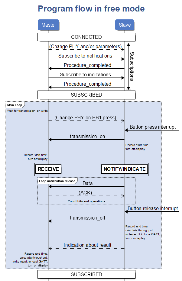
When device is booted, it starts in ADV_SCAN state. After a connection is established, both participants transition to CONNECTED. The master in the connection proceeds to change PHY and connection parameters if that is necessary. For example, if the connection was lost on 2M PHY,the master will request a PHY change after initial connection with 1M PHY. In the firmware, default values #definedfor connection parameters are hard coded on each PHY such as connection interval, slave latency and timeout. On PHY change, master will request the use of these parameters.
After the right parameters are set, the master proceeds to subscribe first to notifications with the gecko_cmd_gatt_set_characteristic_notification command and transition to SUBSCRIBED_NOTIFICATIONS. On success, a gatt_procedure_completed event is received. Use the above command to subscribe to indications and then transition to wait for another gatt_procedure_completed event in SUBSCRIBED_INDICATIONS. On success, a transition to SUBSCRIBED is made. At the same time, the slave checks for changes in the Client Characteristic Configuration for the Notifications and Indications characteristics. When notifications/indications are enabled by the master, the slave also transitions to SUBSCRIBED_NOTIFICATIONS / SUBSCRIBED_INDICATIONS respectively.
In SUBSCRIBED, data transmission can be initialized from the slave by pressing and holding the push buttons. This will make a write without response to the Transmission ON characteristic in the master side GATT database to signal that the transmission is starting. Both sides turn off their LCD display refresh with the gecko_cmd_hardware_set_soft_timer(0, SOFT_TIMER_DISPLAY_REFRESH_HANDLE, 0) call. This way refreshing won’t negatively affect throughput during transmission. The display refreshing is turned on again after the transmission. Start and end times for calculating throughput are taken by using RTCC_CounterGet() value. Master checks raised events for a write to Transmission ON and transitions to RECEIVE after doing the above preparations. The slave transitions to NOTIFY or INDICATE depending on whether the button pressed was PB0 or PB1.
During transmission, master, the receiving side, handles gecko_evt_gatt_characteristic_value events and keeps incrementing the bitsSent and operationCount variables when data is received. It also checks if the event’s att_opcode shows that an indication to Indications characteristic is received, in which case a confirmation is sent back to the slave to acknowledge the successful operation. For indications, the slave must wait for the confirmation from the master before registering the bits as sent. The program stays in the INDICATE state until the last of the confirmations is received and none are left pending (waitingForConfirmation flag variable is used for this).
The transmission ends after the push button is released on the slave side. Releasing the button triggers another write without response to Transmission ON characteristic, at which point the end time is taken and the display is refreshed again, as mentioned above. After calculating the throughput, each side writes the result to their own local GATT database. The slave also sends an indication about the result to the master. This is used when the master device is a PC or mobile device. Afterwards, both sides return to SUBSCRIBED_(NOTIFICATIONS/INDICATIONS) depending on whether both notifications and indications were subscribed to.
Both the master_main and slave_main include a call to handle_universal_events function at the end of each loop. This is a switch-case for checking events such as interrupt signals from buttons and timers, connection parameter updates and le_connection_closed event. They need handling regardless of the main state of the program. The event that is checked is the same that falls through the main state switch.
Example Test Results#
Typical throughput (between 2 BG13 boards):
1M PHY notifications ~740 kbps, indications 20 kbps (50 ms interval)
2M PHY notifications ~1.3 Mbps, indications 40 kbps (25 ms interval)
Coded PHY notifications 85 kbps, indications 5 kbps (200 ms interval)
Setting up#
To run this example you need the following:
2 Wireless Starter Kits (WSTK) if to test between 2 EFR32/BGM
Radio boards with an EFR32[B|M]x/[B|M]GMx device e.g., BRD4305C (BGM13S) or BRD4104A (EFR32BG13)
[Optional] EFR Connect App on your smart phone
Simplicity Studio
Create a new
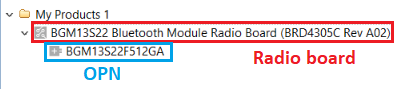
SoC-Emptyapplication project withBluetooth SDKversion 2.12.x or above and selecting your radio board (not an OPN).
*.iscfile in the project tree, select theCustom BLE GATTfield on the upper right side of the GATT configurator, and selectImport GATT from .bgproj filefrom the bottom icon on the right side.Select the
gatt.xmlprovided here, clickSave, and pressGenerate. You should now have a newThroughput Test Serviceand within it four characteristics.Copy the following files to your project:
app.c
app_slave.c
app_master.c
app_utils.h
app_utils.c
lcd_support.bat
Run the lcd_support.bat batch file, which copies the necessary files to use the LCD screen from the SDK directories to your project in the workspace. To run the file, double-click from the project tree within Simplicity IDE.
Add the following to the include paths, for example for GCC: right-click on the project -> Properties -> "C/C++ Build" -> Settings -> "GNU ARM C Compiler" -> Includes): "
{ProjName}/lcd-graphics}" Add the following line to
hal-config.h:
#define HAL_SPIDISPLAY_FREQUENCY (1000000)[OPTIONAL] To use TX Power above +10 dBm on the parts that support it, make the following changes:
Adjust the
TX_POWERmacro used to set your desired TX power inapp_utils.hNote that
gecko_init_afh()is called fromapp.c. Adaptive Frequency Hopping needs to be enabled for TX power levels higher than 10 dBm. You are likely to see a slight drop in throughput when it's active. It is conditionally compiled ifTX_POWERis greater than 100 (10 dBm).The setpoint defined with
TX_POWERand the value returned by stack from command system_set_tx_power may differ, especially with lower values, as discussed here. The TX power is shown on screen in dBm and it is what gets returned by the system_set_tx_power command.
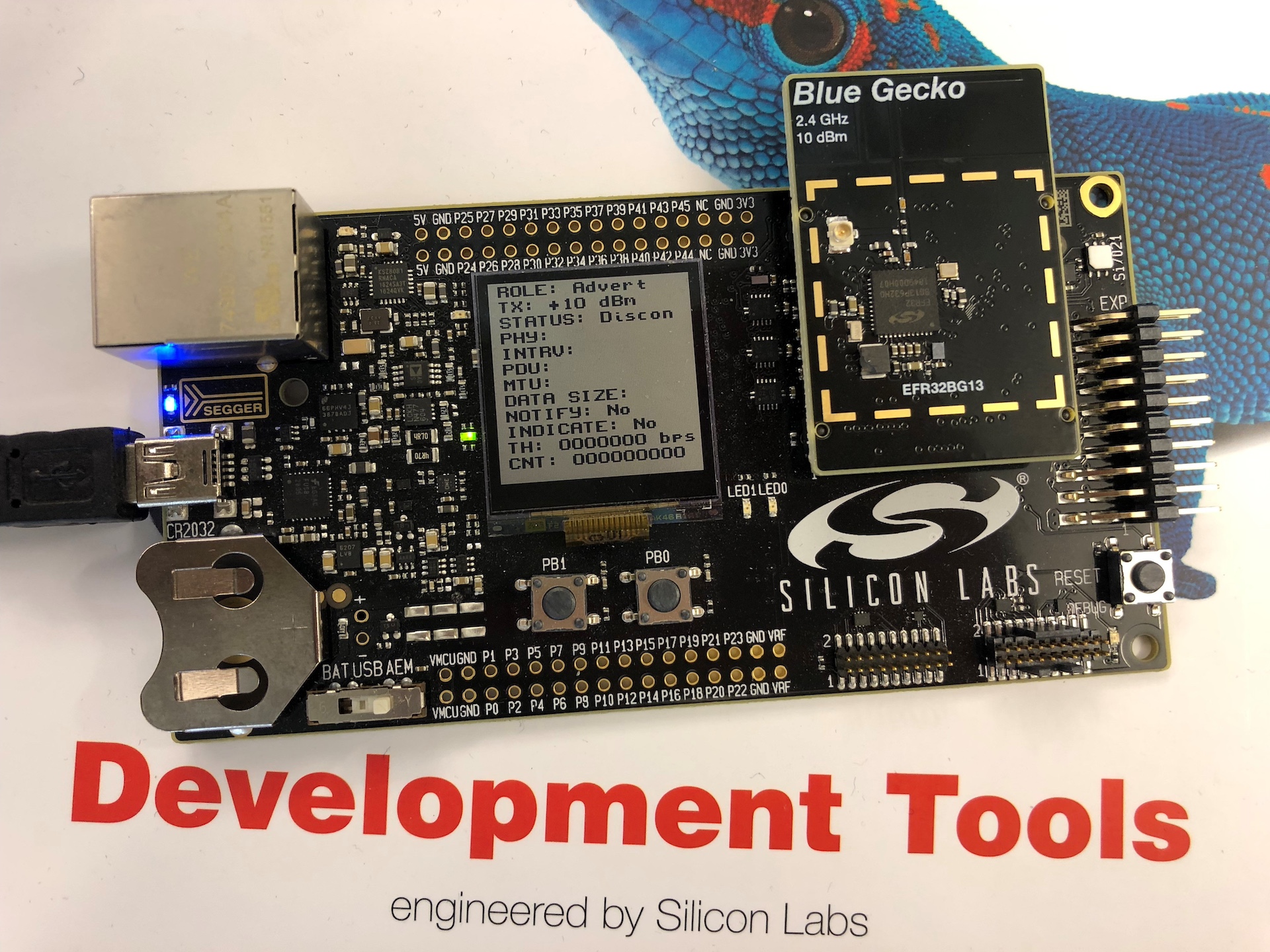
Now, the project should build without errors. When you flash the application, you should see a screen similar to this on your kit.
Usage#
The same Throughput Tester firmware is used for both master and slave devices. The device boots into Slave role by default. Booting to Master role is triggered by holding down PB0 while the RESET-button is pressed. After releasing RESET, the application will start in Master role and connect to any device which has "Throughput Tester" as the device name. (If a more selective scanning approach is needed, modify the process_scan_response function in app_master.c)
Throughput between two WSTKs / Radio Boards#
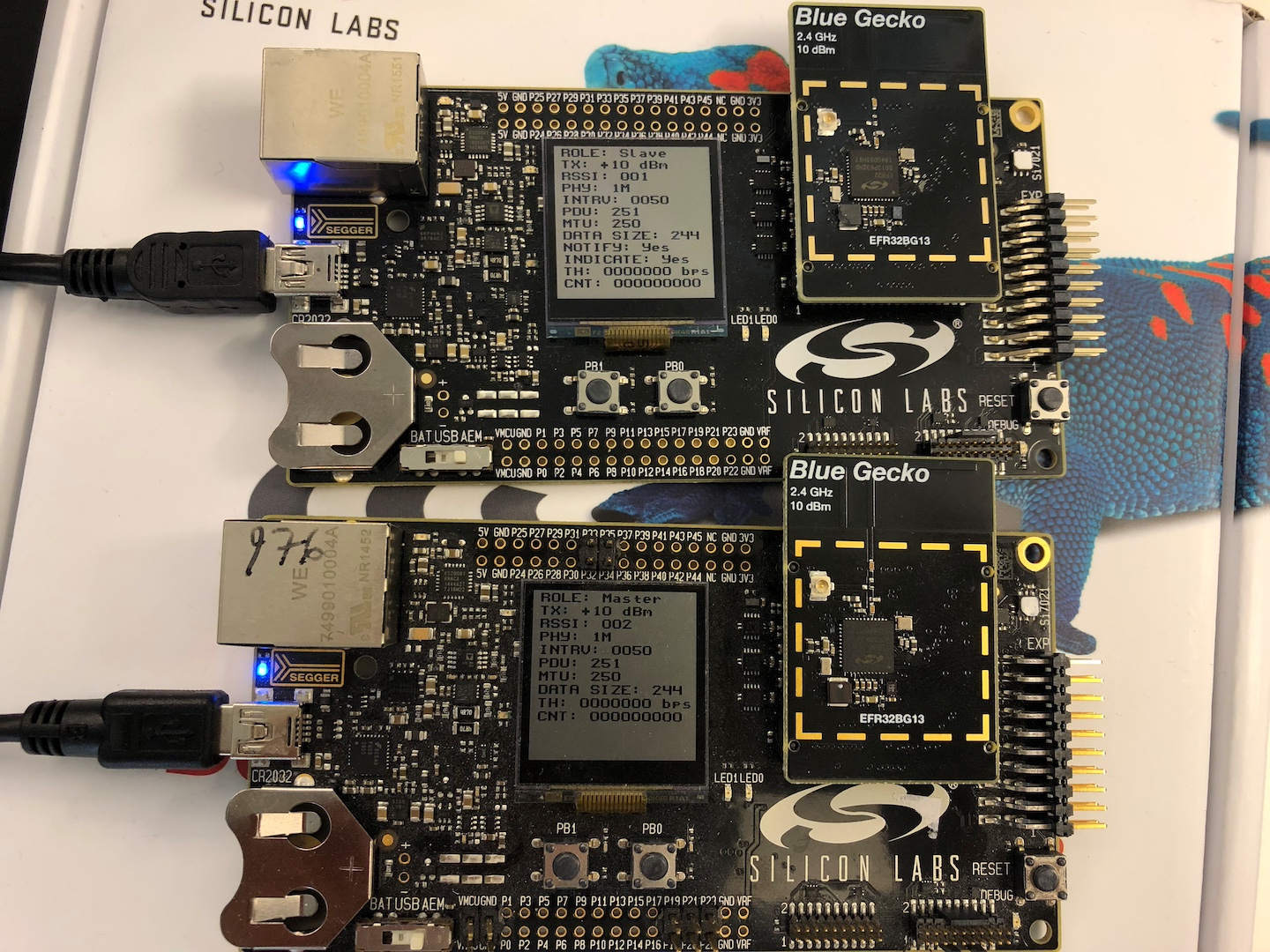
Two (2) radio boards 1.Program both radio boards with the throughput tester firmware as discussed in section How to set up. 2.Set one of the devices as Slave and the other as Master (hold PB0 on boot).
The devices are controlled using the push buttons (PB0 and PB1) of the WSTK. Depending on the device role, the buttons have different functionalities. You can check the role from the display. When not connected, slave device will show "Advert" as in advertiser and master device will show "Scanner". When connected, the role field will change to slave/master, status field will change to show the RSSI and some connection parameters will appear on the display.
Master Device Functionality#
Pressing PB1 (during scanning)
Change the PHY used for scanning advertisements between 1M and Coded PHY (S8). New connections are initiated with the chosen PHY.
Pressing PB1 (during connection)
In this setting, the master has the possibility to change the PHY to be used in the current connection. The PHYs will be changed in a sequence, as illustrated in the figure below.
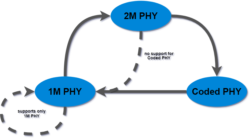
On certain devices the Coded PHY is not supported. In these use cases the PHY will only be changed between 1M and 2M. If no other PHY than 1M is supported, the change will not be triggered.
Slave Device Functionality#
In slave role, the device starts an advertisement set with both 1M and Coded PHYs. It advertises the "Complete Local Name" AD data type with the name "Throughput Tester".
Depending on which button is pressed and held down, the slave will generate data and send either notifications or indications. After the connection is established, the buttons have the following functions:
Press and hold PB0 to send notifications.
Press and hold PB1 to send indications.
You will see the screen stop refreshing while holding a button and the throughput result and operation count will update (TH and CNT) after releasing to ensure that the device is fully dedicated to data exchange over the Bluetooth link and the throughput doesn't get affected by the screen refreshing operation.
Throughput between Radio Board and Smart Phone#
A smart phone can be used as a GATT client. You will need an app like the Blue Gecko (Android / iOS) which can connect to Bluetooth devices and read and write characteristics. The steps to conduct a throughput test are the following:
Find the slave device in the
Bluetooth Browserby the name ofThroughput Testerand connect to it.You should see a service (UUID: bbb99e70-fff7-46cf-abc7-2d32c71820f2) with four characteristics down at the bottom.
Characteristic
Description
UUID
Indications255B array for the indication data
6109b631-a643-4a51-83d2-2059700ad49f
Notifications255B array for the notification data
47b73dd6-dee3-4da1-9be0-f5c539a9a4be
Transmission ONUsed to indicate start (1) and end (0) of the transmission
be6b6be1-cd8a-4106-9181-5ffe2bc67718
Throughput resultThe throughput test result is written to this characteristic after each calculation to be viewed by the client
adf32227-b00f-400c-9eeb-b903a6cc291b
Subscribe to the
Throughput resultandIndicationsorNotificationscharacteristics (click the icon). The display on the kit should show"Yes"forNOTIFYand/orINDICATEdepending on what you chose.Press the buttons on the slave device to transmit. You should see data coming in the corresponding characteristic value field in the app.
You can see the throughput measurement result from the display or from the characteristic value in the app. The value is a 4-byte array where e.g., a hexadecimal value of 0x30A1 should be read as 0xA130=41264 bps.
Throughput between Radio Board and 3rd Party Device#
As you might guess from the mobile app approach, you can use any BLE-capable 3rd party device, such as a USB dongle or laptop Bluetooth adapter to issue the GATT commands to write and read the above characteristics. One example with the NCP host application is discussed in later sections.