Energy Harvesting Applications with EFR32xG22E#
This document describes different methods of energy harvesting to power EFR32 wireless devices without battery or line power. Also known as "Ambient IoT", this enables devices to operate without needing batteries and battery replacement.
Device Compatibility#
This document provides guidance for the EFR32xG22E family, which includes:
EFR32MG22E
EFR32BG22E
EFR32FG22E
Overview#
Energy harvesting allows IoT devices to operate without batteries or line power. Battery-less devices have the following advantages:
Increased flexibility of installation (no need for power outlets)
Reduction in cost of maintenance (no need for battery replacement)
Reduction in cost of batteries
Reduce environmental impact (no battery waste)
Fewer shipping restrictions compared to devices with batteries
Energy can be harvested from a variety of sources. Common ones include:
Solar
Kinetic (vibration, motion, or button press)
Thermal
Magnetic
RF
When the energy source is intermittent, energy can be stored using storage methods such as:
Supercapacitors
Thin film capacitors
Solid state capacitors
Hybrid lithium capacitors
Rechargeable batteries
Printed batteries
Calculating the energy budget and storage requirements depends on the application. Most ambient IoT devices will spend a majority of their time in low-power sleep modes such as EM2 or EM4. When an event occurs and there is enough power to run, the goal is for the Wireless MCU to complete the task quickly and go back to sleep mode. How much energy is required will depend on things like run time, the amount of data to process, and radio transmit power. Some energy sources are "trickle" sources and provide a continuous amount of power (for example, a solar panel). These sources are good for applications that are always on. Other sources are "transient" and provide a limited amount of energy per event (for example, from a switch press).
Available energy can be measured in micro-Joules (µJ) or milliwatt-Hours (mWh). The EFR32xG22E consumes about 150 µJ to boot from PoR and 17 µJ to boot from EM4.
Optimizing MCU Software#
Many power saving and time saving (same thing) optimizations are possible for the EFR32xG22E. The device firmware can also track how much power is available and adjust operations accordingly (for example, how often to transmit, how much data to transmit, or other tasks like flash erases).
In EM2 and EM3, RAM retention has a significant impact on current consumption. Reducing RAM retention (if possible) can yield significant power savings.
Waking from EM4 takes a significant amount of power to reinitialize the device. For longer sleep periods, this consumes less energy than EM2, but if the device will wake often, it can be more efficient to stay in EM2 and not have to reinitialize the device. Cold starting the device (Power on Reset) takes even more time and energy, so the device should remain in EM4 instead of completely powered off if possible.
The EFR32xG22E has reduced security features compared to other Series 2 devices and has security on par with Series 1 devices. This change results in significant reductions in power consumption and boot time from power off or from EM4. See application note AN1447 for more information.
The type of wake up sources varies with energy mode. See the EMU section of the EFR32xG22E reference manual for more information. Peripherals that use the low frequency oscillator are active in EM2, and so wakeup sources include LETIMER, I2C, and EUART. Wakeup sources that are available in all energy modes include pin interrupts, BURTC, and RFSENSE. This allows a device to wake periodically, upon input from another device, or to wake when a radio transmitter is present. With RFSENSE, a scanner can wake devices when it is present, letting them remain in a low power mode, such as EM4, the rest of the time.
Available energy, as well as charge rate and discharge rate can be measured if the PMIC being used supports it. For example, the AEM13920 has a feature called Average Power Monitoring, which can measure power from the source to the storage element and from the storage element to the load. The Silicon Labs PMIC part, EFP01 has a coulomb counter that measures power consumed.
The voltage on storage devices can also be measured with the IADC, but converting voltage across an energy storage element to how much energy is available for the application requires detailed knowledge about the discharge curve of the storage element. The IADC has internal inputs for supply pins AVDD, IOVDD, DVDD, DECOUPLE, and VSS. The supplies AVDD, IOVDD, and DVDD are divided by 4 so they can be easily measured by the internal voltage reference. IADC readings can also be taken from IO pins, and connected to other storage devices such as a supercapacitor that is not directly connected to the device. A voltage divider can be used to bring the reading into range, analog inputs are limited to the lower of AVDD and IOVDD. For more information on IADC measurements see Application notes AN1189 (IADC) and AN0018.2 (Series 2 Supply Voltage Monitoring).
Data stored in RAM will be retained across energy modes EM0 - EM3. In EM4, ordinary RAM is not retained, but there are 128 bytes of BURAM that are preserved across every type of reset except for brownout and power on reset. Data that needs to remain after the device is powered off must be written to flash. Data can be stored in flash using direct writes to flash memory or a software library like NVM3. Note that erasing a flash page requires a significant amount of time (typically 12.9 ms) and current. If NVM3 memory is repacked, it will require at least one page erase. Because code cannot be executed out of flash during a write or erase, it is difficult to stage flash erase operations in parallel with other tasks.
Optimizing Radio Power#
A typical wireless project will initialize the wireless stack in software, and depending on the wireless protocol, may join a network or establish a connection to another device. In order to reduce power consumption, Ambient IoT devices can operate in transmit only modes that do not require continuous network connection, such as
Bluetooth Beaconing
Zigbee GPD
TX only proprietary packets
Where possible, the device can transmit radio packets directly using the RAIL abstraction layer, rather than initializing the radio stack.
Radio settings, including transmit power, amount of data, transmission PHY (1M vs 2M), sleep interval, beacon interval, and number of beacons can have a significant effect on power consumption.
These parameters can be selected and dynamically adjusted by an energy-aware algorithm ensure the device meets its power budget. If energy is limited, it can decrease the number of beacons, sleep longer between transmits, reduce the amount of data sent, and reduce transmit power. If energy is in abundance, it can transmit more often, transmit more information, and use higher transmit power.
Hardware and Kits#
There are lots of evaluation boards for various devices. Silicon Labs provides the EFR32xG22E Explorer Kit (EK2710A) which features a EFR32MG22E. This kit does not have an energy harvesting power source or storage, but it can be connected to these devices through the Qwiic connector. For more information about these boards, see User Guide UG582.
E-peas provides a PMIC and evaluation boards that can be coupled to our kits. The e-peas PMIC can work with energy harvesting devices like PV, thermal, or kinetic. The device configuration is set with GPIO pins (either jumpers or connected to the EFR32). Status pins (also GPIO) indicate the PMIC state (shutdown, ready) to the EFR32.
The EFR32xG22E Explorer Kit features a EFR32MG22E on a board with a J-Link debugger, a Qwiic connector, and a mikroBus socket that allows expansion boards or "shields" to be attached to it. Shields include energy-harvesting-specific shields which contain an e-peas PMIC and can be connected to power sources and storage devices.
The following shield boards are available as a kit from Silicon Labs. The kit number for is xG22-EK8200A, and information about these boards is available in user guide UG591:
BRD2710A - EFR32xG22E Explorer Kit Board
BRD8201A - AEM13920 PMIC for dual energy sources
BRD8202A - AEM00300 PMIC for kinetic pulse sources
BRD8203A - Alternate battery and super-capacitors
BRD8204A - AC Input Adapter
BRD8205A - DC Input Adapter
Lab equipment such as Digital Multi Meters (DMMs) and Oscilloscopes can be used to evaluate and debug the power management of these designs. Voltage measurements at different nodes can be taken to determine how much power is being generated, how much is available in storage, and which parts are powered up. Measuring voltage does not affect the circuit. For devices connected with screw terminals, the screw is connected to the terminal and is a good location to put a probe.
Current measurements are slightly more complicated because they must go in series with the circuit being measured. Current meters measure the voltage across a known resistor. The lower the current range, the higher the resistance. In order to measure the current consumption in modes like EM2 (usually less than 10 µA), the resistance is usually too high for the EFR32 to start up. A workaround to this is to put the current meter in series with a short, start the device, and then remove the short to measure current.
The EFR32xG22E Explorer Kit has the footprint for a mini-simplicity header on the back of the board, although this connector is not populated. Mini-simplicity headers can be used to power the device from a board that has AEM, and use Energy Profiler to measure the board's current consumption. See application note AN958 for more information about the mini-simplicity header.
Software Examples#
Several energy optimized examples are available on our GitHub page.
No. | Example | Document | Protocol | Type |
|---|---|---|---|---|
1 | Bluetooth - SoC Energy Harvesting Sensor | BLE | Sensor | |
2 | Bluetooth RAIL - SoC Energy Harvesting Sensor | Bluetooth RAIL | Sensor | |
3 | Bluetooth RAIL - SoC Energy Harvesting Kinetic Switch | Bluetooth RAIL | Switch | |
4 | Bluetooth - SoC Energy Harvesting Application Observer | BLE | Observer | |
5 | Zigbee - SoC GPD Energy Harvesting Sensor | Zigbee | Sensor | |
6 | Zigbee - SoC GPD Energy Harvesting Switch | Zigbee | Switch | |
7 | Zigbee GPC - SoC Energy Harvesting Observer | Zigbee | Observer |
Sample App Measurements#
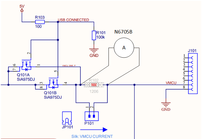
Measurements were conducted on the Dual Harvester shield and the Kinetic Harvester shield from the Kinetic Energy Harvesting bundle BRD8200A.
Two types of measurements are conducted:
V_MCU voltage measurements
Showing the output voltage of the PMIC on the harvester board supplying the EFR32xG22E on the Explorer Kit.
IV_MCU current measurements
As a voltage measurement using an oscilloscope across a 10 Ω resistor.
As a current measurement using a DC power analyzer configured as an ammeter inserted in the supply path.
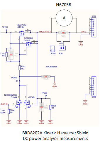
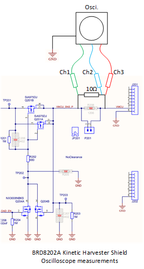
Voltage and current measurement setup for bt_rail_soc_energy_harvesting_kinetic_switch#
These measurements are conducted on the Kinetic Switch shield. The EFR32xG22E Explorer Kit is programmed with the sample application. The Kinetic Switch board is attached to the EFR32xG22E Explorer Kit. Two types of measurements are conducted:
Oscilloscope measurements showing concurrent traces of V_MCU and I_MCU. (I_MCU is measured as a voltage drop across a 10 Ω resistor inserted in the supply path).
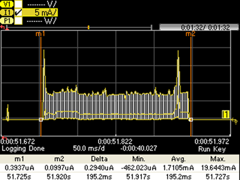
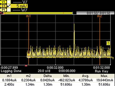
I_MCU Current trace measurement, where a DC power analyzer, Agilent N6705B, configured as an ammeter, is inserted in series with the supply path.
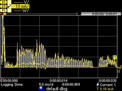
N6705B current trace measurement of I_MCU
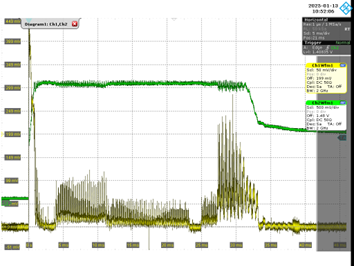
Oscilloscope Voltage measurements of V_MCU and I_MCU (as voltage drop across 10 Ω resistor). Voltage across shunt resistor on Y-axis.
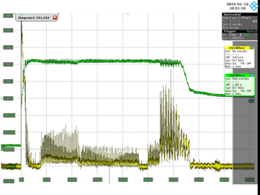
Oscilloscope Voltage measurements of V_MCU and I_MCU (as voltage drop across 10 Ω resistor). V_MCU voltage on Y-axis.
Voltage and current measurement setup for: BLE and ZigBee Sensor Applications#
These measurements are conducted on the Dual Harvester shield.
The EFR32xG22E Explorer Kit is programmed with the sensor sample applications:
ZigBee
BT Rail SoC
BT SoC
The Dual Harvester shield is attached to the EFR32xG22E Explorer Kit as described in UG591.
SRC2 on the Dual Harvester shield is supplied with 2.6 V from a current limited voltage supply.
Two types of measurements are conducted:
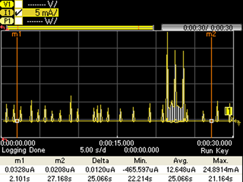
I_MCU Current trace measurement, where a DC power analyzer, Agilent N6705B, configured as an ammeter, is inserted in series with the supply path. Average current measured of the radio transmission.
I_MCU Current trace measurement, where a DC power analyzer, Agilent N6705B, configured as an ammeter, is inserted in series with the supply path. Average current measured across the entire application cycle.
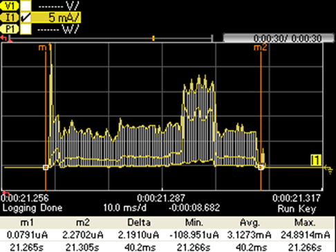
Zoom on the wake up period of the application
Markers set at the application repeat cycle, 90 seconds
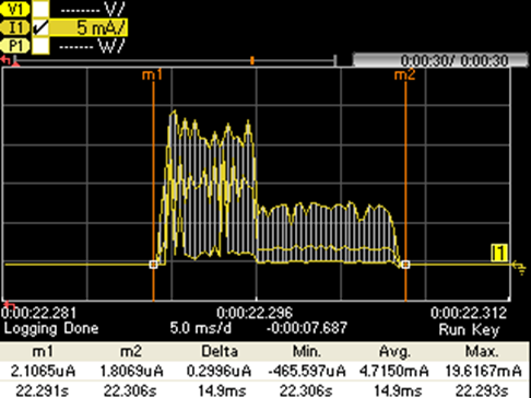
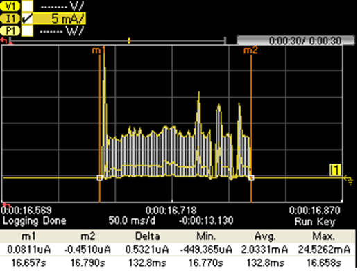
Zoom on the first wake up period of the application
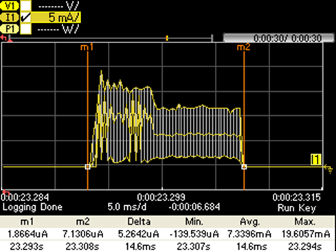
Zoomed at the second wakeup period of the application
Zoom on the third wake up period of the application
Zoomed on the three TX periods of the application
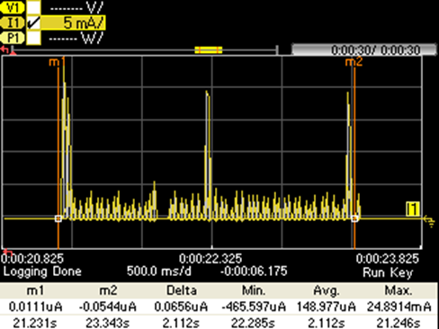
Markers set at the application repeat cycle, 25 seconds. max of 500 M readings per datalog
Zoom on the wake up period of the application
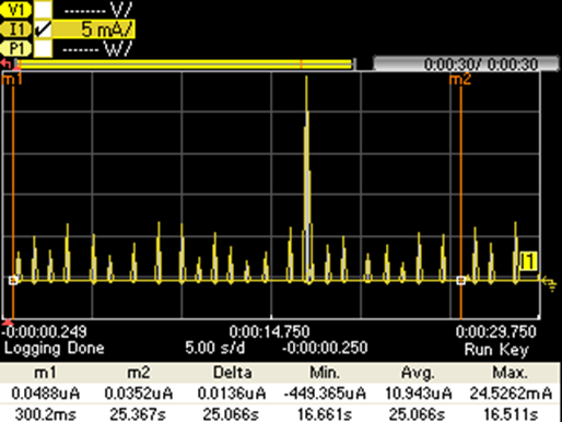
Markers set at the application repeat cycle, 25 seconds