Memory Layout#
Memory layout of a C/C++ project is controlled by the linker in your toolchain. Memory layout in this documentation means the location of functions and data in flash memory and RAM on a Silicon Labs EFR32/EFM32/SIXX. When using GCC, the GNU Linker is using GNU linker scripts (.ld) to control the memory layout and when using IAR Embedded Workbench IAR ILINK is using linker configuration files (.icf) to control the memory layout of the application.
Simplicity SDK provides the Simplicity Studio Project Configurator which, can be used to generate these toolchain-dependent linker files. These linker files will be created based on the project description, target device, and components used in a project. Using the generated linker files, the sections of the applications will be placed in a deterministic way, which will allow the application to be used with Silicon Labs devices.
Toolchains#
GCC and IAR are the supported toolchains. The GCC generated linker script,
linkerfile.ld is placed in the autogen folder. The IAR-generated linker
configuration file, linkerfile.icf is also placed in the autogen folder. The
generated project files will refer to these files.
Note that the linker files are auto generated based on the components included in the project and will be overwritten whenever the application is re-generated.
Graphical View of Standard Memory Layout#
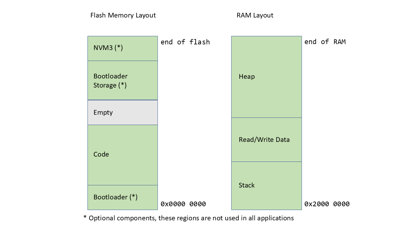
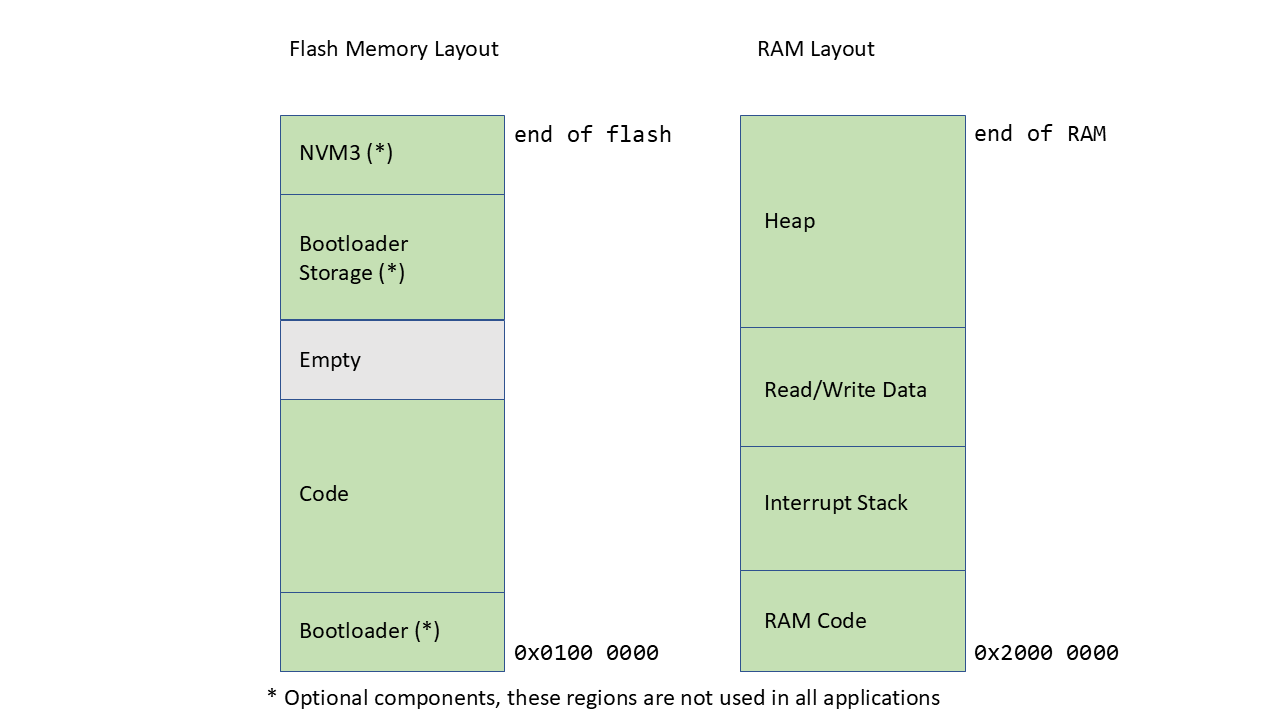
This is a graphical view of a typical memory layout of an application built using the Silicon Labs Simplicity SDK. This shows the relative placement of various sections. Note that some of the sections in the image are optional and do not have to be present in all applications.
Some devices may have the main flash located at a different address than what the graphical view shows. See the reference manual of your selected device for the exact memory location of flash and RAM.
Typical Memory Layout for Series 2 (EFR32xG2x/EFM32PG2x)#
Typical Memory Layout for Series 30 (SixG30x)#
Section Details#
Different memory sections are described starting with the lowest memory address.
Bootloader#
An application using the Simplicity SDK can optionally choose to use a bootloader. When using a bootloader, an area of flash will be reserved for the bootloader and will be unavailable for the application code. Some devices will have dedicated bootloader flash areas, while other devices will have to use parts of the main flash for bootloader code. All series-2 devices use the first parts of main flash for the bootloader.
To allocate flash memory for the bootloader with the Simplicity SDK, add the
Bootloader Application Interface component to the application. The presence of
this component in the project will trigger the reservation of a fixed size
bootloader. On the EFR32xG21 device the bootloader size is 16 kB while on
EFR32xG22 the bootloader size is 24 kB.
For a different size bootloader, manual modifications of the auto-generated linker files is needed. See the Bootloader user guide UG266 for more Bootloader-specific documentation.
Code#
Application code is next in the memory layout. This is where functions and read only data are placed.
Bootloader Storage#
The application Bootloader has the option to use parts of main flash on the
device as storage space for the firmware update images. To safely reserve space
in the memory map, the application can include the Flash Storage Support component.
This component will provide source code and a configuration file that the
application can use to tune the amount of storage needed.
When including the Flash Storage Support component, the default flash reservation
is half of the main flash size minus 16 kB. To modify the size, change the
SL_BOOTLOADER_STORAGE_SIZE option, which is located in the
sl_storage_config.h configuration file. The size of the bootloader storage
area is highly application-dependent and should be a fixed size once a product
with a bootloader is deployed.
Note that the configured bootloader storage size used when building the application and the bootloader storage size used when building the bootloader must match. The user will have to manually ensure that the bootloader storage size and location is correctly configured between the bootloader project and the application project.
NVM3#
Simplicity SDK provides a way to store persistent key-value objects into the main flash. This data is persistent between resets and firmware updates and can be used for general storage and in wireless applications for token storage. When you add NVM3 as a component to a project, parts of main flash are reserved for a single NVM3 instance. The NVM3 storage will be placed at the end of main flash and the size of the NVM3 region is configurable by the application. The default size of the NVM3 instance is 40 kB.
The configuration for the NVM3 instance is placed in the file
nvm3_default_config.h, which is copied into the project when a project is
generated. The NVM3 size configuration is called NVM3_DEFAULT_NVM_SIZE. For
more documentation on NVM3 and other NVM3 related configurations, see
application note AN1135: Using Third Generation Non-Volatile Memory (NVM3) Data
Storage.
RAM Code#
Application code classed as time-critical is placed in RAM because the non-volatile memory for Series 3 is external FLASH, which may have a less predictable access time. The RAM code is still saved in FLASH, but it is copied to RAM in the startup code.
For series 30, the latency introduced by a L2 cache miss when fetching an instruction is about a hundred QSPI clock cycles and cannot be planned for. This latency can be longer if authentication (AXiP) is used.
It is recommended to place your interrupt routines and time-critical code
in RAM using the macro SL_CODE_RAM.
SL_CODE_RAM void TIMER0_IRQHandler(void)
{
  // All functions called here should also be in RAM.
}
To help identify what code is time-critical, the component ICACHE Disable can
be used to disable the instruction cache in testing. This will show what code
fails when the execution is slowed down.
On Series 30, the RAM code is accessed through an address alias starting at 0x0080 0000, reducing the contention on the bus between data and code accesses.
Stack#
The stack and heap are used by the application to allocate dynamic memory. The stack is normally used to allocate local memory to function variables and call frames, which means that applications with deep call stacks will typically need to allocate a larger stack than applications with shallow call stacks. With Simplicity SDK, customer applications can configure the size of the stack.
An application will have to configure the stack size based on the estimated maximum stack usage. This number can be difficult to determine exactly and might change between SDK releases and application versions, so a normal strategy would be to over-allocate the stack space to have some head room for application changes. Always change the stack configuration from the default value to suit the application needs.
The size of the stack is configured in the sl_memory_config.h configuration
file using the SL_STACK_SIZE option. This configuration file is copied to the
application when it's first generated. Modifying this configuration option will
modify the stack size accordingly.
If at any point the application uses more stack than is allocated, the device will trigger a usage fault and the developer can detect this error condition during development.
Read/Write Data#
This section is used by initialized (.data) and uninitialized (.bss) global and static variables. The initialization values for the variables are saved in FLASH and loaded in RAM in the startup code.
Heap#
Whenever an application uses malloc() in any part of the software, a portion
of RAM needs to be allocated to the central heap. The size of the allocated heap
is application dependent. Small applications might not need any heap at all
while other applications might use a lot of heap. The heap region is placed after
the rest of the RAM-based content and the heap is growing towards the end of RAM.
Security Aliasing in Series 3 Devices#
Series 3 devices implement ARM TrustZone standards by aliasing all memory address spaces; one alias for non-secure access, and one for secure access. All memory addresses and registers can be accessed through these two distinct aliases where bit 28 determines the security attribute:
Non-Secure Alias: Default access mode. Bit 28 cleared. (e.g., RAM at 0x20000000)
Secure Alias: Used for TrustZone-based security features. Bit 28 set. (e.g., RAM at 0x30000000)
The memory address alias determines whether the bus transaction is processed as Secure or Non-Secure. While the non-secure alias is accessible by default, the secure alias becomes essential for TrustZone applications, as all secure transactions on the SLAXI Bus must pass through the secure address space.
External Flash Architecture in Series 3 Devices#
External flash is inherently more vulnerable to physical attacks, prompting the implementation of robust security measures:
Encryption: Protects code and data confidentiality
Authentication: Ensures code integrity and prevents tampering
Code Regions: Configurable memory sections with distinct security policies
Configuring Code Regions#
Flash memory is divided into distinct regions, each serving a specific purpose. Common regions include:
Bootloader Code Region: Contains the bootloader code, responsible for initializing the system and potentially handling firmware updates.
Application Code Region: Stores the main application code.
Data Region: Used for storing non-volatile data, such as configuration settings or logs.
Proper configuration of code regions is essential for optimizing memory usage and implementing appropriate security measures. By default, flash memory is partitioned among these common regions, with the Bootloader Code Region occupying approximately 32 kB. The remaining flash memory is generally split evenly between the Application Code Region and the Data Region, with each consuming roughly half of the available space.
Resizing Code Regions#
Flash partitioning cannot be modified directly from the device's main core. Instead, they must be configured through the Security Engine (SE) using Simplicity Commander. Refer to the Simplicity Commander Documentation for detailed instructions on commands to configure Code Regions. However, when adjusting code region sizes via Simplicity Commander, you must also update your project's linker script to reflect these changes:
Open your project's .slcp file as a text file (not through Studio's UI).
Add or modify template contributions for code region sizes. Example:
template_contribution:
- name: code_region0_size
    value: 32768 # 0x8000
- name: code_region1_size
    value: 1048576 # 0x100000
Close and reopen your project in Simplicity Studio.
Perform a force generation to regenerate the linker script with the updated region sizes.
Authenticated Execute in Place (AXiP)#
AXiP is a security feature that cryptographically authenticates code as it's executed directly from external flash memory, protecting against code tampering attacks.
Series 3 devices have AXiP enabled by default on all Code Regions (Bootloader and Application). To disable it (when security is not a concern):
Use Simplicity Commander to disable the feature.
Add the appropriate axip_region
<Region ID>_disable component to your project.Force the regeneration of the linker script to utilize the freed memory space by triggering a Force Generation from Studio's UI.
Development Considerations#
When working with AXiP during development:
Memory Overhead: AXiP adds authentication data to flash memory, reducing available space for application code.
OTP Bit Conservation: During development, use the SkipAxipIVRoll command to prevent exhaustion of one-time programmable (OTP) bits. Refer to the Simplicity Commander Documentation for details on the command.
For production devices, carefully evaluate security requirements against performance needs when configuring AXiP settings.