AT Command Examples#
The following AT command examples show how to operate the module in different modes.
Note!
All commands must be terminated with
\r\n(CRLF).
Create an Access Point#
at+rsi_opermode=6,1,16,0This command sets the operating mode of the module.
at+rsi_band=0This command sets the operating band of the module.
at+rsi_initThis command initializes the module.
at+rsi_ipconf=0,192.168.50.1,255.255.255.0,192.168.50.1This command can be used optionally in this flow to configure the IP (192.168.50.1 in this example) of the AP.
If this command is not issued, a default IP of 192.168.100.76 will be used.
at+rsi_apconf=1,AP_SSID,2,2,12345678,300,2,4This command will configure the SSID of the AP to AP_SSID and password will be set to 12345678.
at+rsi_join=AP_SSID,0,2This command will create the Access Point with SSID AP_SSID.
A client device (Named Device A in this example) can now associate to the AP, open sockets and transfer data.
For example,
at+rsi_ltcp=5001,5,0Opens a server TCP socket inside the module with port number 5001 with TOS (type of service) type 0 and max clients support count as 5.
A client socket at the remote node (Device A) can connect to the server socket.
To send a test string This is a test from the module to the remote node, issue the below command
at+rsi_snd=1,14,0,0,This is a testIf the remote node (Device A) sends data, the module receives the data and transfers to the Host with a AT+RSI_READ message
Another client (Named Device in this example) can also connect to the Access Point in the module and data transfer can be executed between Device A and Device B through the AP. A maximum of 4 clients are supported.
Associate to an AP (with WPA2-PSK Security)#
at+rsi_opermode=0,1,260,0This command sets the operating mode of the module.
at+rsi_band=0This command sets the operating band of the module.
at+rsi_initThis command initializes the module.
at+rsi_scan=0This command scans for the Access Points and reports the APs found.
Note!
After a scan, if the user want to join an AP as enterprise client then user need to issue a soft reset first and then follow the flow of commands as in “Associate to an Enterprise Security enabled Access Point as a client”
at+rsi_psk=1,12345678This command configures the PSK to be used to associate to the Access Point.
at+rsi_join=Test_AP,0,2,2This command associates the module to the AP.
It is assumed that the SSID of the AP is Test_AP with WPA2-PSK security key of 12345678.
at+rsi_ipconf=1,0,0,0This configures the IP address of the module in DHCP mode.
at+rsi_dnsserver=1,0,0Optional command to provide the IP address of a DNS server.
Note!
If the user wants to use the DNS command to get DNS server IP, then the user must enable tcp_ip_feature_bit_map[8] in the oper_mode command.
at+rsi_dnsget=\<domain_name\>,1Optional command to resolve IP of a given domain name.
at+rsi_ltcp=5001,5,0Opens a server TCP socket inside the module with port number 5001 with TOS(type of service) type 0 and max clients support count as 5.
Now connect another client (called Device A in this example) to the same Access Point and open a client socket to bind to the module’s socket.
To send a test string This is a test from the module to the remote node, issue the below command
at+rsi_snd=1,14,0,0,This is a testIf the remote node (Device A) sends data, the module receives the data and transfers to the Host with a AT+RSI_READ message
Associate to an AP (with WPA3-PSK Security)#
at+rsi_opermode=0,1,260,2147483648,8192Set the operating mode of the module.
at+rsi_band=0Set the operating band of the module.
at+rsi_initInitialize the module.
at+rsi_scan=0Scan for the Access points and report the APs found.
Note!
After a scan, if the user want to join an AP as enterprise client then user need to issue a soft reset first and then follow the flow of commands as in “Associate to an Enterprise Security enabled Access Point as a client”.
at+rsi_psk=1,12345678Configure the PSK to be used to associate to the Access Point.
at+rsi_join=Test_AP,0,2,7,96,0,0,1Associate the module to the AP.
It is assumed that the SSID of the AP is Test_AP with WPA3-PSK security key of 12345678.
at+rsi_ipconf=1,0,0,0Configure the IP address of the module in DHCP mode.
at+rsi_dnsserver=1,0,0Optional command to provide the IP address of a DNS server.
Note!
If the user wants to use the DNS command to get DNS server IP, then the user must enable tcp_ip_feature_bit_map[8] in the oper_mode command.
at+rsi_dnsget=\<domain_name\>,1Optional command to resolve IP of a given domain name.
at+rsi_ltcp=5001,5,0Open a server TCP socket inside the module with port number 5001 with TOS(type of service) type 0 and max clients support count as 5.
Now connect another client (called Device A in this example) to the same Access Point and open a client socket to bind to the module’s socket.
To send a test string This is a test from the module to the remote node, issue the below command
at+rsi_snd=1,14,0,0,This is a testIf the remote node (Device A) sends data, the module receives the data and transfers to the Host with a AT+RSI_READ message
Associate to an AP (with WEP Security)#
at+rsi_opermode=0,2,4,0This command sets the operating mode of the module.
at+rsi_band=0This command sets the operating band of the module.
at+rsi_initThis command initializes the module.
at+rsi_scan=0This command scans for APs and reports the APs found.
at+rsi_wepkey=0,ABCDE12345,0,0,0This command configures the PSK to be used to associate to an Access Point.
at+rsi_join=Test_AP,0,2,3This command associates the module to the AP.
at+rsi_ipconf=1,0,0,0This configures the IP address of the module in DHCP mode.
at+rsi_ltcp=5001,5,0Opens a server TCP socket inside the module with port number 5001 with tos(type of service) type 0 and max clients support count as 5.
Now connect another client (called Device A in this example) to the same Access Point and open a client socket to bind to the module’s socket.
To send a test string This is a test from the module to the remote node, issue the below command
at+rsi_snd=1,14,0,0,This is a testIf the remote node (Device A) sends data, the module receives the data and transfers to the Host with a AT+RSI_READ message
Associate to an AP with WPS Enabled#
at+rsi_opermode=0,2,4,0This command sets the operating mode of the module.
at+rsi_band=0This command sets the operating band of the module.
at+rsi_initThis command initializes the module.
at+rsi_scan=0This command scans for available Aps and reports the Aps found.
at+rsi_join=,0,2This command associates the module to the AP using WPS push button method. Note that, we have to send null in place of ssid .
at+rsi_ipconf=1,0,0,0This command configures the IP address of the module in DHCP mode.
at+rsi_ltcp=5001,5,0Opens a server TCP socket inside the module with port number 5001 with tos (type of service) type 0 and max clients support count as 5.
Now connect another client (called Device A in this example) to the same Access Point and open a client socket to bind to the module’s socket.
To send a test string This is a test from the module to the remote node, issue the below command
at+rsi_snd=1,14,0,0,This is a testIf the remote node (Device A) sends data, the module receives the data and transfers to the Host with a AT+RSI_READ message.
Associate to an AP with Enterprise Security#
The example demonstrates the flow for EAP-TLS mode.
at+rsi_opermode=2,0,4,0This sets the operating mode of the module.
at+rsi_band=0This command sets the operating band of the module.
at+rsi_initThis command initializes the module.
at+rsi_eap=TLS,MSCHAPV2,user1,password1This command sets the Enterprise mode.
at+rsi_scan=0This command scans for Aps and reports the Aps found.
Note!
After a scan, if the user want to join an AP with WPA2-AES PSK then user need to issue a soft reset first and then follow the flow of commands as in “Associate to an Access Point (with WPA2-PSK security) as a client”.
at+rsi_cert=1,cert_len,key_password,<TLS certificate>This command provides the TLS certificate to the module
at+rsi_join=Test_AP,0,2,4This command associates the module to the AP. It is assumed that the SSID of the AP is Test_AP.
at+rsi_ipconf=1,0,0,0This command configures the IP address of the module in DHCP mode.
at+rsi_ltcp=5001,5,0Opens a server TCP socket inside the module with port number 5001 with tos(type of service) type 0 and max clients support count as 5.
Now connect another client (called Device A in this example) to the same Access Point and open a client socket to bind to the module’s socket.
To send a test string This is a test from the module to the remote node (Device A), issue the below command
at+rsi_snd=1,14,0,0,This is a testIf the remote node (Device A) sends data, the module sends the received data with a AT+RSI_READ message to the Host.
PER Tx Mode in Burst Mode#
at+rsi_opermode=8This command sets the operating mode of the module.
at+rsi_band=0This command sets the operating band of the module.
at+rsi_feat_frame=0,1,0,0,1,0This command sets the correct RF type and path
at+rsi_initThis command initializes the module.
at+rsi_antenna=0This is the command for antenna .
at+rsi_setregion = 1,4This command configures the region to worldwide
at+rsi_per=1,127,139,1000,0,6,0,0,0,0This command sends the packets in burst mode in channel number 6, with packet length 1000, with max power, with data rate 6Mbps.
at+rsi_per=0To stop transmission
PER Tx Mode in Continuous Mode#
at+rsi_opermode=8This command sets the operating mode of the module.
at+rsi_band=0This command sets the operating band of the module.
at+rsi_feat_frame=0,1,0,0,1,0This command sets the correct RF type and path
at+rsi_initThis command initializes the module.
at+rsi_antenna=0This is the command for antenna
at+rsi_setregion = 1,4This command configures the region to worldwide
at+rsi_per=1,127,139,260,1,6,0,0,0,0This command starts Continuous mode in channel number 6, with packet length 260, with max power, with data rate 1Mbps.
at+rsi_per=0To stop transmission
PER Tx Mode in Continuous Wave Mode#
at+rsi_opermode=8This command sets the operating mode of the module.
at+rsi_band=0This command sets the operating band of the module.
at+rsi_feat_frame=0,1,0,0,1,0This command sets the correct RF type and path
at+rsi_initThis command initializes the module.
at+rsi_antenna=0This is the command for antenna .
at+rsi_setregion = 1,4This command configures the region to worldwide
at+rsi_per=1,127,139,260,1,6,0,0,0,0This command starts Continuous mode in channel number 6, with packet length 260, with max power, with data rate 1Mbps.
at+rsi_per=0To stop transmission
at+rsi_per=1,127,0,260,2,6,0,0,0,0This command sends the packets in Continuous Wave mode 2 in channel number 6, with packet length 260, with max power, with data rate 1Mbps.
PER Receive Mode#
at+rsi_opermode=8This command sets the operating mode of the module.
at+rsi_band=0This command sets the operating band of the module.
at+rsi_feat_frame=0,1,0,0,1,0This command sets the correct RF type and path
at+rsi_initThis command initializes the module.
at+rsi_setregion = 1,4This command configures the region to worldwide
at+rsi_per_stats=0,1This command here is used to see the WLAN Receive stats.
at+rsi_per_stats=1This command is used to stop the WLAN PER RECEIVE STATS
WLAN Scan in Client#
at+rsi_opermode=0,1,4,0This command sets the operating mode of the module.
at+rsi_band=0This command sets the operating band of the module.
at+rsi_initThis command initializes the module.
at+rsi_scan=0This command scans for available APs in the channels mentioned in channel_bit_map_2_4 in 2.4GHz, channel_bit_map_5 in 5GHz and reports the APs found.
at+rsi_join=test,0,2,0This command associates the module to the AP in open mode.
at+rsi_bgscan=1,1,10,4,10,15,20,1This command enables the back ground scan functionality in module.
Here instant bgscan is enabled hence module will send probe requests in the air on to the channels mentioned in the channel bitmap and results will go to host.
at+rsi_ipconf=1,0,0,0This command configures the IP address of the module in DHCP mode.
Roaming as a Client#
at+rsi_opermode=0,1,4,0This command sets the operating mode of the module.
at+rsi_band=0*This command sets the operating band of the module.
at+rsi_initThis command initializes the module.
at+rsi_scan=0This command scans for available APs in the channels mentioned in channel bitmap and reports the APs found.
at+rsi_join=test,0,2,0This command associates the module to the AP in open mode.
at+rsi_bgscan=1,1,10,4,10,15,20,1This command enables the back ground scan functionality in module.
Here instant bgscan is enabled hence module will send probe requests in the air and results will go to host and in background scan will be continued based upon the parameters given in the command.
at+rsi_roam_params= 1,5,2This command enables roaming in module.
at+rsi_ipconf=1,0,0,0This command configures the IP address of the module in DHCP mode.
WMM Powersave as a Client#
at+rsi_opermode=0,1,4,0This command sets the operating mode of the module.
at+rsi_band=0This command sets the operating band of the module.
at+rsi_initThis command initializes the module.
at+rsi_scan=6,testThis command scans for available AP in the given channel with the given SSID and reports, if the AP is found.
at+rsi_wmm_config=1,0,0,1This command enables the WMM feature in the module.
at+rsi_join=test,0,2,0This command associates the module to the AP which is in open mode.
at+rsi_pwmode=1This command configures the power save mode 1 in the module.
at+rsi_ipconf=1,0,0,0This command configures the IP address of the module in DHCP mode.
Open a Multicast IPv4 Socket#
at+rsi_opermode=0,1,4,0This command sets the operating mode of the module.
at+rsi_band=0This command sets the operating band of the module.
at+rsi_initThis command initializes the module.
at+rsi_scan=0This command scans for APs and reports the APs found.
at+rsi_join=Test_AP,0,2,0This command associates the module to the AP.
at+rsi_ipconf=1,0,0,0This configures the IP address of the module in DHCP mode.
at+rsi_multicast=1,239.0.0.0To join IPv4 multicast group with address 239.0.0.0.
at+rsi_ludp=5001To open ludp socket with port number 5001.
at+rsi_multicast=0,239.0.0.0To leave multicast group with address 239.0.0.0.
Sends an AT command with a mix of ASCII and Array input#
Let us consider the example of user gain table for giving the input in ASCII and array input.
For 2.4 GHz#
at+rsi_opermode=6,1,48,0This command sets the operating mode of the module.
Note!
It is not mandatory that the first parameter of opermode is AP only. Users can use any other mode.
If the user wants to measure the TX power after loading the gain table then they need to use the '8' as the opermode parameter (PER mode). Once the gain table is loaded successfully in the module, the user can use the PER AT command sequence (burst/continuous mode) to measure the TX power.
at+rsi_band=0This command sets the operating band of the module.
at+rsi_initThis command initializes the module.
at+rsi_gain_table=1,0, 67,array(3,0,13,1,34,20,20,2,34,28,28,3,34,32,32,4,34,36,36,5,34,38,38,6,34,40,40,7,34,38,38,8,34,36,36,9,34,32,32,10,34,32,32,11,34,24,24,12,34,16,24,13,34,12,12,2,17,255,20,16,16,4,17,255,26,20,20)This command is used to set the user gain table. User can give input either in hex or decimal. For instance if the user intends to give input in decimal format, then the following procedure can be followed to run the Application using Docklight tool to provide input in decimal format.
Go to Docklight and provide sequence by double clicking on the left side provided send sequences column and enter the sequence normally up to init.
For at+rsi_gain_table command, Please enter the sequence normally in ASCII format, up to third parameter as shown in below figure.


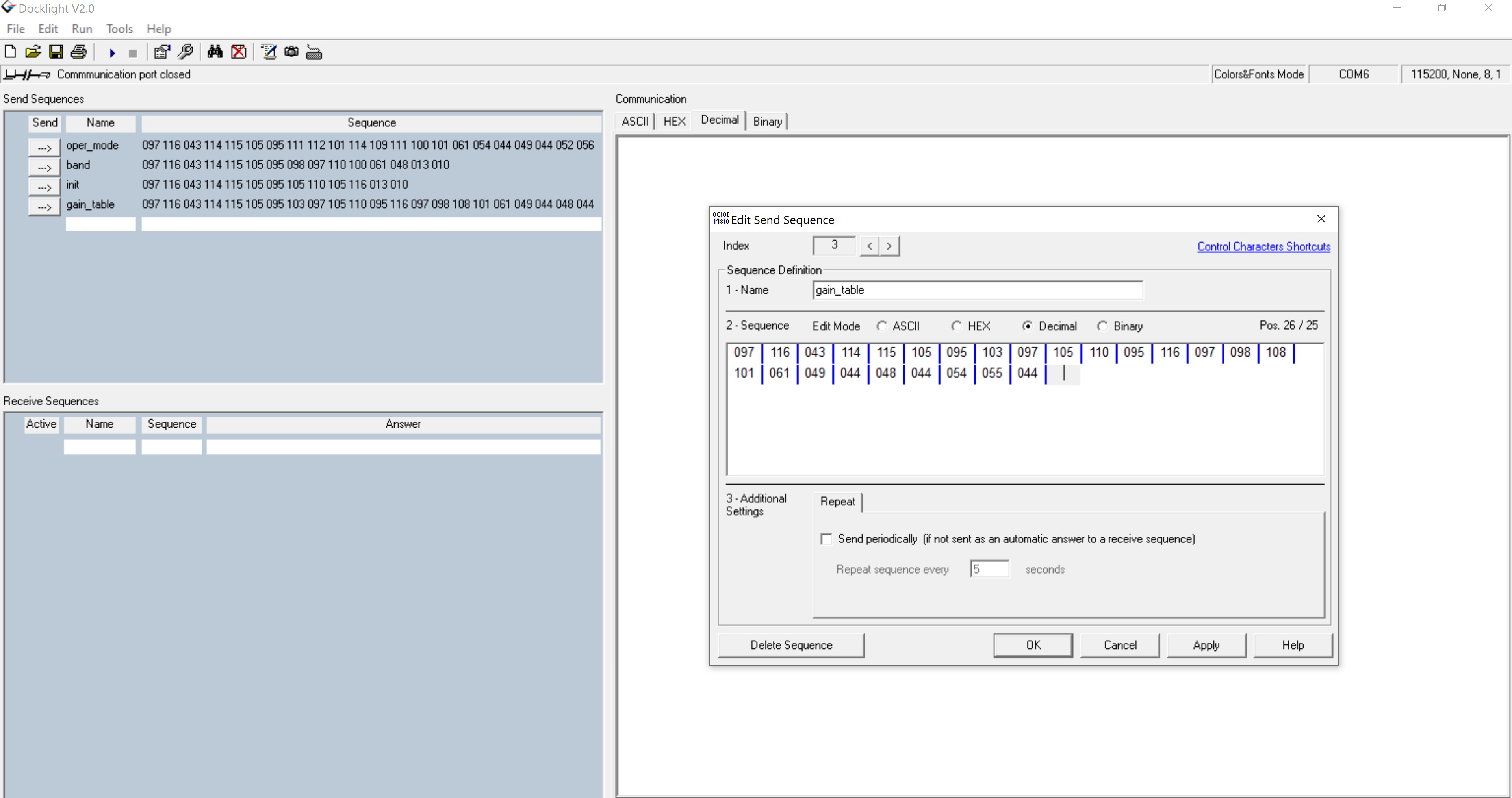
Now for giving fourth Parameter i.e Payload ,user need to change the mode of the input either hex or decimal. In the screenshot decimal format is shown.
After the switching the mode to decimal, the input sequence will look like the following Figure.

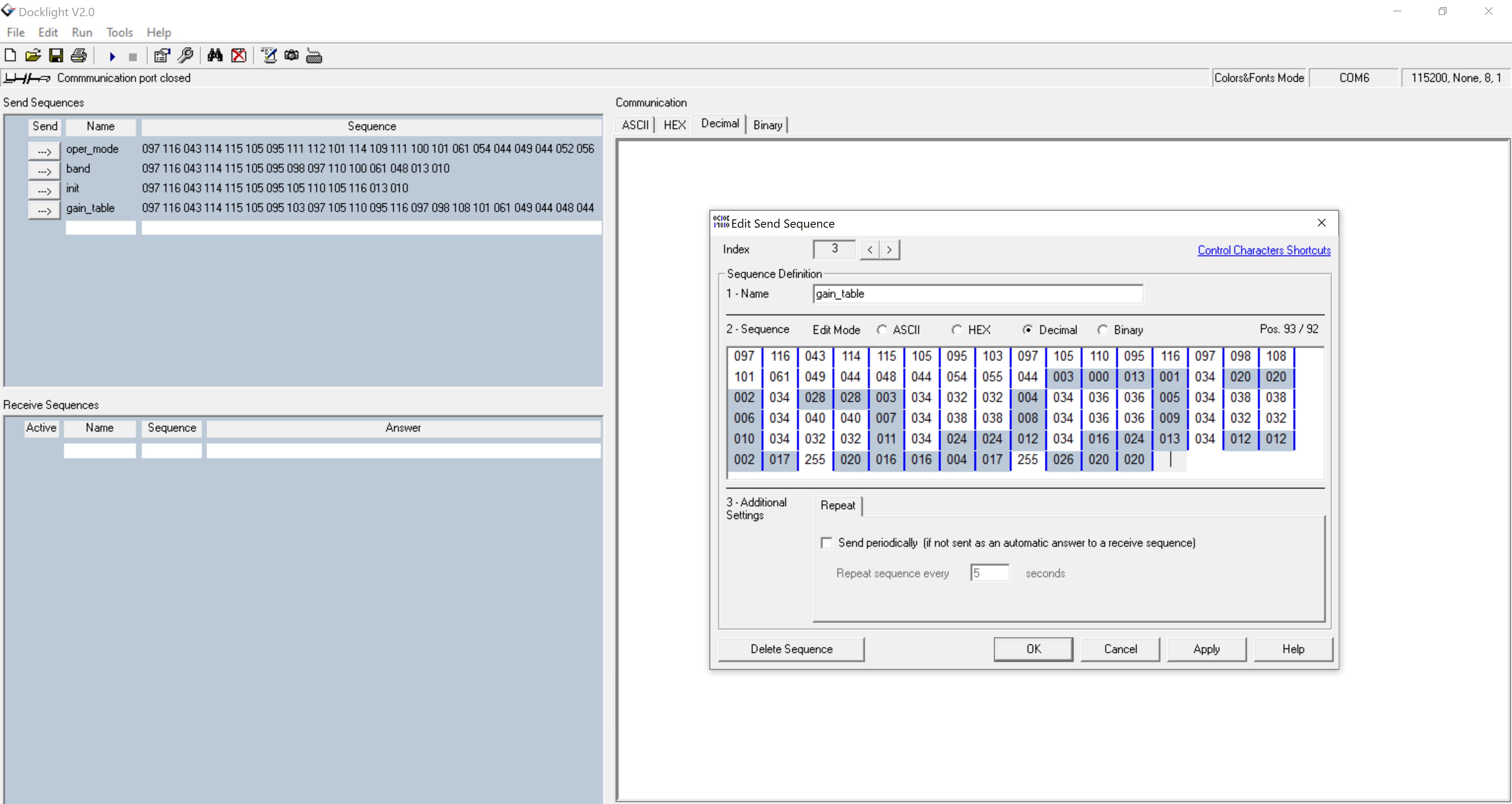
Now from fourth parameter on wards, give the input in decimal format without any commas as the Application is expecting an array input(decimal) as shown in below figure.

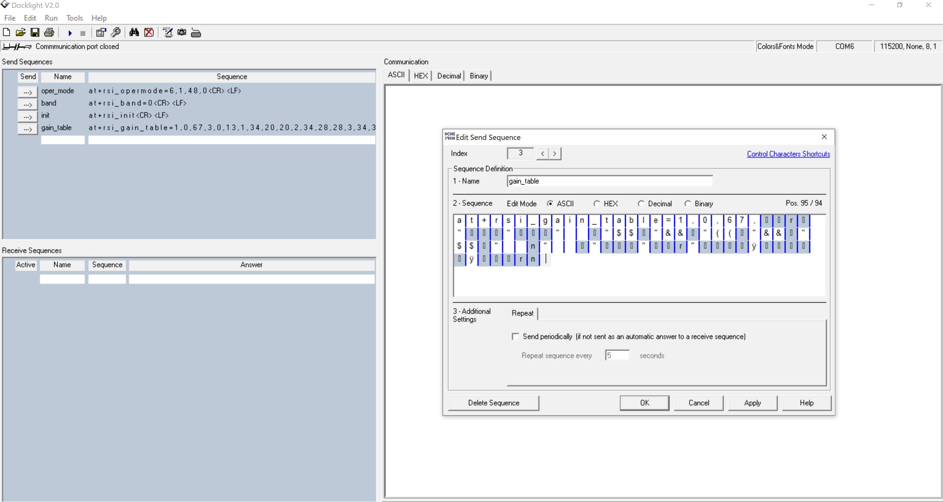
After providing the payload of the gain table, the user has to again switch back to the ASCII format for providing <CR> and <LF>. Please follow the below figure. With this the gain_command sequence is successfully completed.

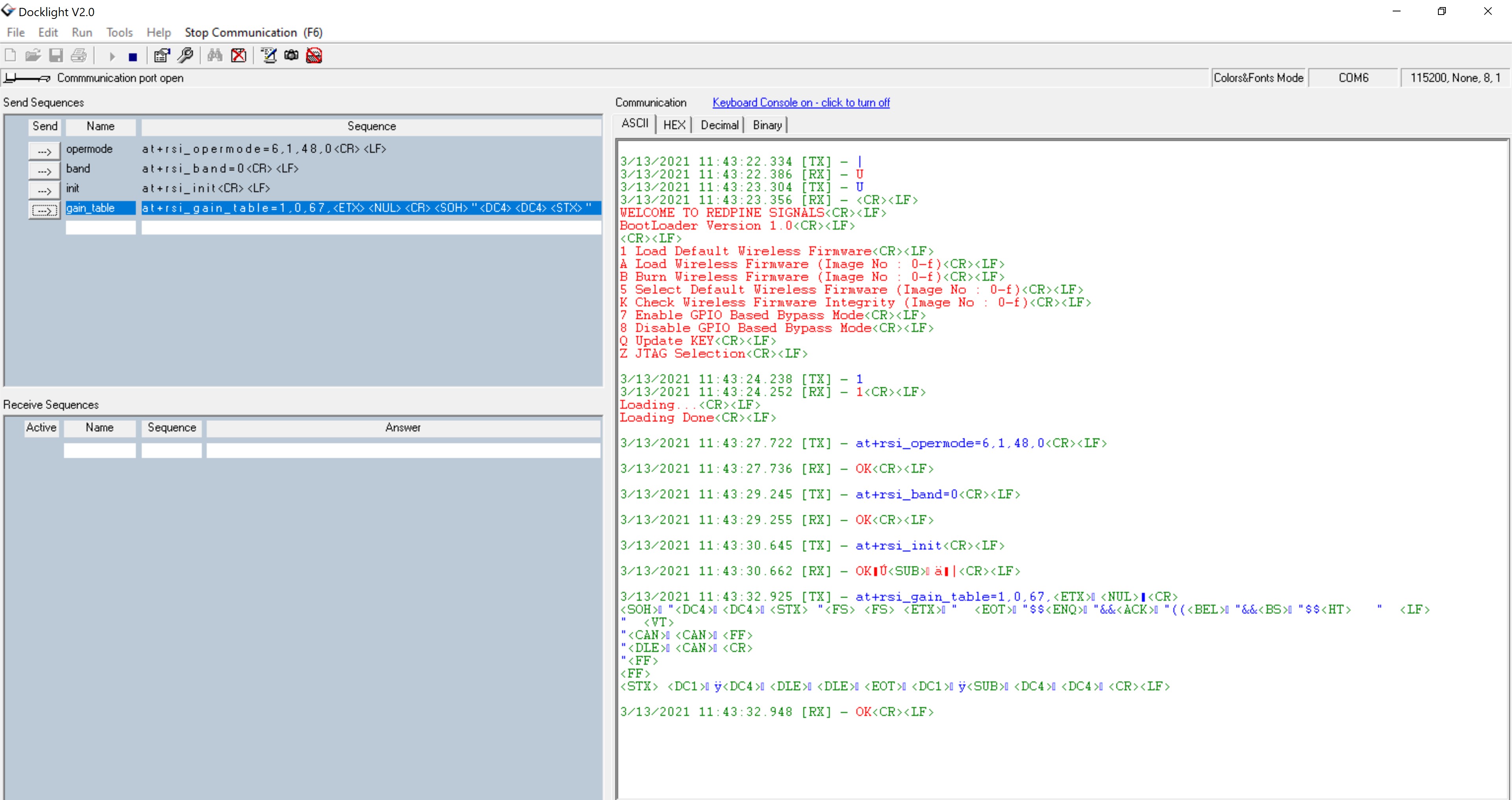
Once the sequence of commands and gain_table parameters are given properly, and executed the output will look like the below Figure.

For 5 GHz#
at+rsi_opermode=6,1,48,0This command sets the operating mode of the module.
Note!
It is not mandatory that the first parameter of opermode is AP only. Users can use any other mode.
If the user wants to measure the TX power after loading the gain table then they need to use the '8' as the opermode parameter (PER mode). Once the gain table is loaded successfully in the module, the user can use the PER AT command sequence (burst/continuous mode) to measure the TX power.
at+rsi_band=1This command sets the operating band of the module.
at+rsi_initThis command initializes the module.
at+rsi_gain_table=2,0,35,array(2,0,6,1,9,10,2,8,9,100,4,4,3,6,8,149,3,3,4,6,7,2,4,1,9,10,2,8,10,3,6,8,4,6,7)This command is used to set the user gain table. User can give input either in hex or decimal. For instance if the user intends to give input in decimal format, then please consider the following
Please follow the below Procedure to run the Application using Docklight tool to provide input in decimal format.
Go to Docklight and provide sequence by double clicking on the left side provided send sequences column and enter the sequence normally up to init.
For at+rsi_gain_table command, Please enter the sequence normally in ASCII format, up to third parameter as shown in below figure.


Now for giving fourth Parameter i.e Payload, user need to change the mode of the input to decimal in which each ASCII character is equivalent to three decimal digits.
After the switching the mode to decimal, the input sequence will look like the following Figure.
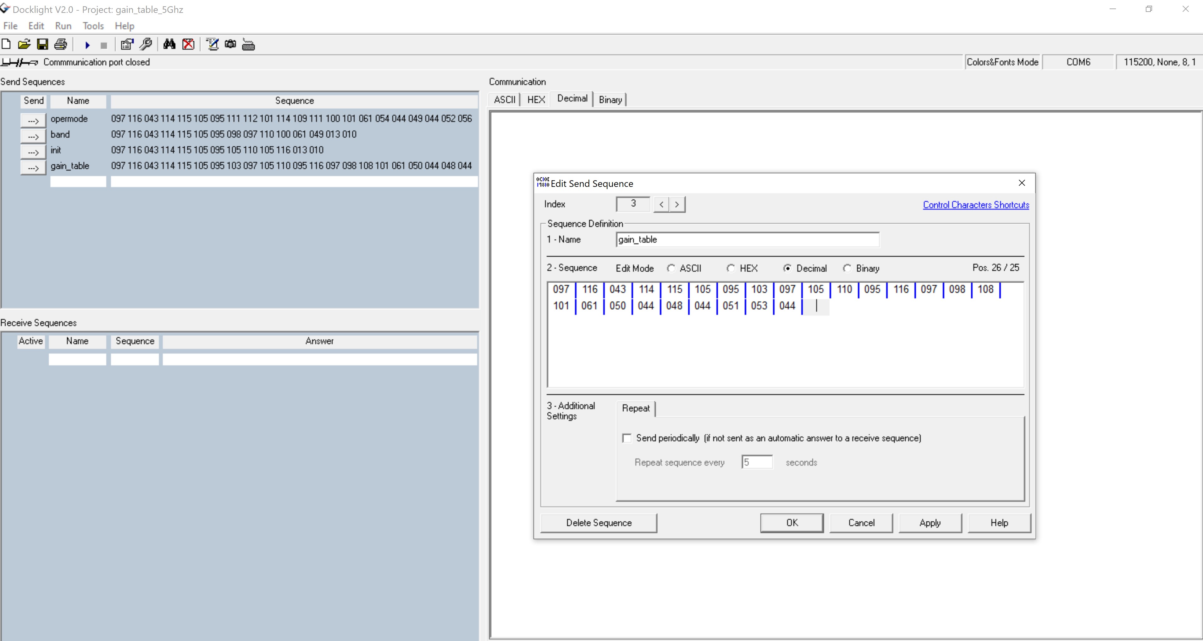

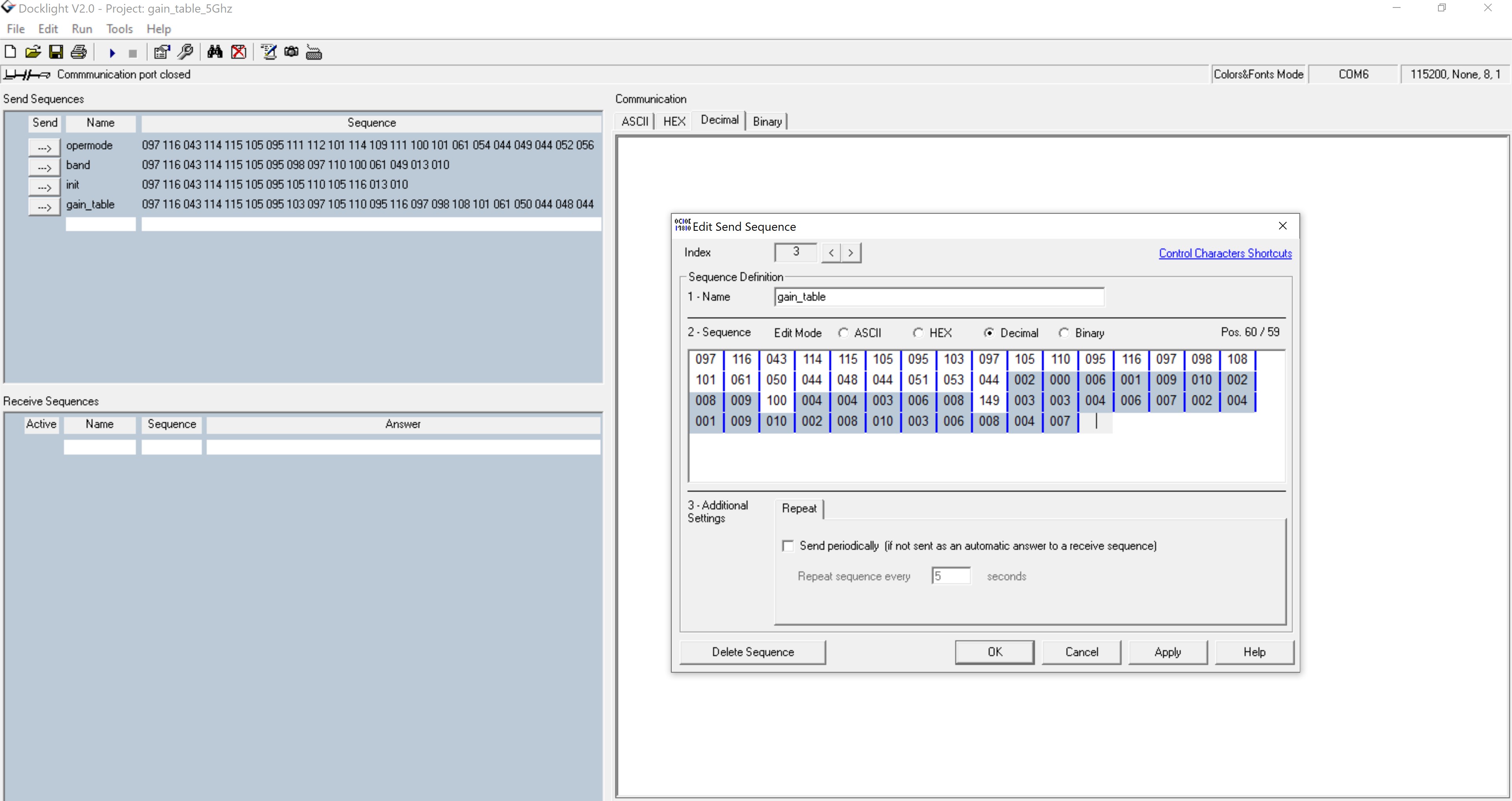
Now from fourth parameter on wards, give the input in decimal format without any commas as the Application is expecting an array input(decimal) as shown in below figure.

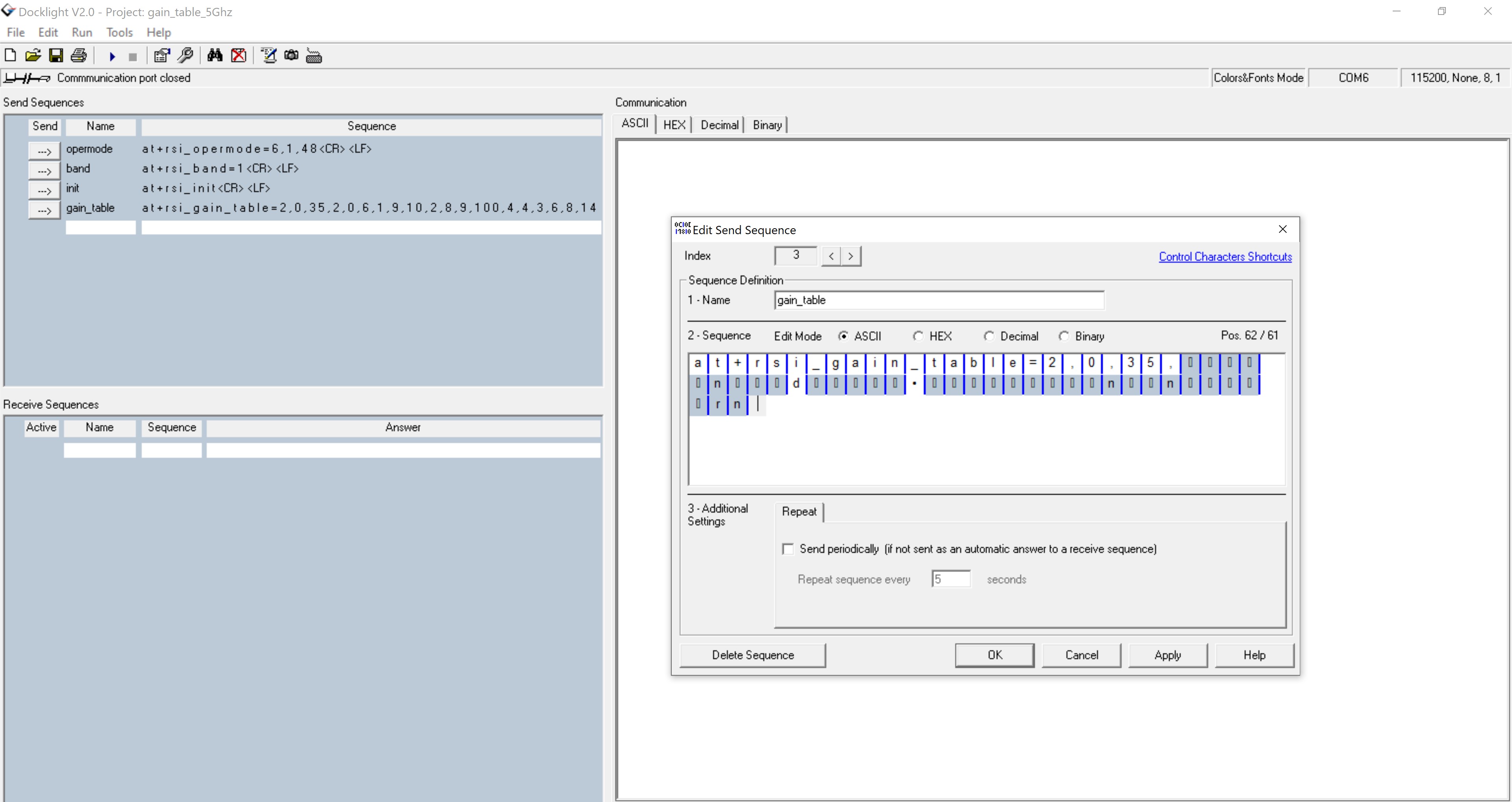
After providing the payload of the gain table, the user has to again switch back to the ASCII format for providing <CR> and <LF>. Please follow the below figure. With this the gain_command sequence is successfully completed.

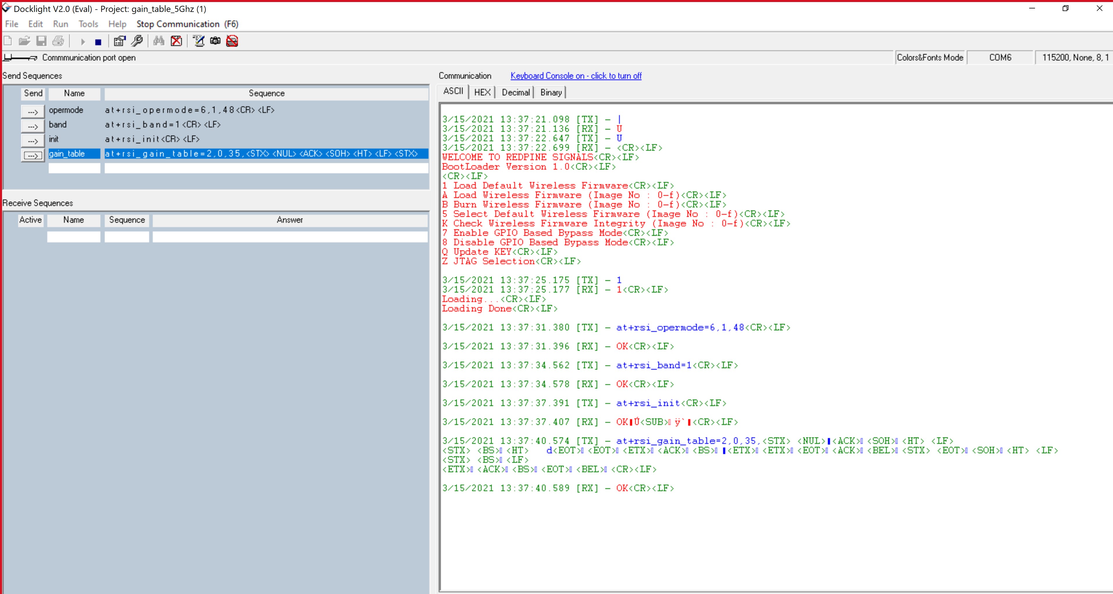
Once the sequence of commands and gain_table parameters are given properly, and executed the output will look like the below Figure.

Open a UDP broadcast IPv4 Socket in Client Mode#
at+rsi_opermode=0,1,4,0This command sets the operating mode of the module.
at+rsi_band=0This command sets the operating band of the module.
at+rsi_initThis command initializes the module.
at+rsi_scan=0This command scans for APs and reports the APs found.
at+rsi_psk=1,987654321This command configures the PSK to be used to associate to the Access Point.
at+rsi_join=Test_AP,0,2,2This command associates the module to the AP.
at+rsi_ipconf=1This command configures the IP address of the module in DHCP mode.
at+rsi_ludp=5000,0,0Opens an UDP server socket inside the module with port number 5000 with tos (type of service) type 0 and socket bitmap[0] (synchronous data read).
To send a test string 12345678 from the module to the remote node (Device A), issue the below command
at+rsi_snd=1,200,255.255.255.255,5000,12345678If the remote node (Device A) sends data, the module sends the received data with an AT+RSI_READ message to the Host.
at+rsi_snd=1,750,192.168.43.255,5000,123456789012345678901234567890123456789012345678901
2345678901234567890123456789012345678901234567890123456789012345678901234567890123
4567890123456789012345678901234567890123456789012345678901234567890123456789012345
6789012345678901234567890123456789012345678901234567890123456789012345678901234567
8901234567890123456789012345678901234567890123456789012345678901234567890123456789
0123456789012345678901234567890123456789012345678901234567890123456789012345678901
2345678901234567890123456789012345678901234567890123456789012345678901234567890123
4567890123456789012345678901234567890123456789012345678901234567890123456789012345
6789012345678901234567890123456789012345678901234567890123456789012345678901234567
8901234567890123456789012345678901234567890
Open a UDP broadcast IPv4 Socket in Access Point Mode#
at+rsi_opermode=6,1,18,0This command sets the operating mode of the module.
at+rsi_band=0This command sets the operating band of the module.
at+rsi_initThis command initializes the module.
at+rsi_ipconf=0,192.168.12.105,255.255.255.0,192.168.12.105This command configures the IP address of the module.
at+rsi_apconf=0,UDP_TEST,2,2,12345678,100,3,3This command will configure the SSID of the AP to UDP_TEST and password will be set to 12345678.
at+rsi_join=UDP_TEST,0,2,6This command associates the module to the AP.
at+rsi_ludp=5000,0,0Opens an UDP server socket inside the module with port number 5000 with tos (type of service) type 0 and socket bitmap[0] (synchronous data read).
at+rsi_snd=1,25,255.255.255.255,5000,Sigmavision_TRHH:60100067If the remote node (Device A) sends data, the module sends the received data with an AT+RSI_READ message to the Host.
Wireless Firmware Upgradation Example in STA mode#
The firmware of the module can be upgraded through web page**. Execution:**
Bring up the Silabs_STA using the following commands:
at+rsi_opermode=0,1,22,2147483648,2097152
at+rsi_band=0
at+rsi_init
at+rsi_scan=0,Silabs_AP
at+rsi_psk=1,13456789
at+rsi_join=Silabs_AP,0,2,2
at+rsi_ipconf=1,0,0,0
Give the IP address of the module in the browser(in this case 192.168.1.3), Redpine configuration page will be open.
Click on Administration.
Choose an .rps file from PC and click on upgrade.
After clicking upgrade button on webpage, module will send asynchronous notification
AT+RSI_FWUPREQModule has to issue the following command:
at+rsi_fwupokIf host has failed to give above command within specified timeout(~20 seconds), request will expire and upgradation process terminates.
After the firmware upgradation is successful, a popup message "Firmware Upgraded Successfully" will appear on webpage screen. And asynchronous success message
AT+RSI_FWUPSUCCESSis send to host from the module.
Wireless Firmware Upgradation Example#
The firmware of the module can be upgraded through web page**. Sequence of events:**
Start the Silicon labs device as an AP.
Allows stations to connect to update firmware through webpage.
A Laptop having WiFi card can be used as Wireless station.
Silicon Labs device creates a network and acts as router between the connected stations
Upgrade the received Firmware into the device.
Execution#
Bring up the Silabs_AP using the following commands:
at+rsi_opermode=6,1,18, 2147483648,2097152
at+rsi_band=0
at+rsi_init
at+rsi_apconf=0,Silabs_AP,0,0,0,100,5,4
at+rsi_join=Silabs_AP,0,2,0,0,0,0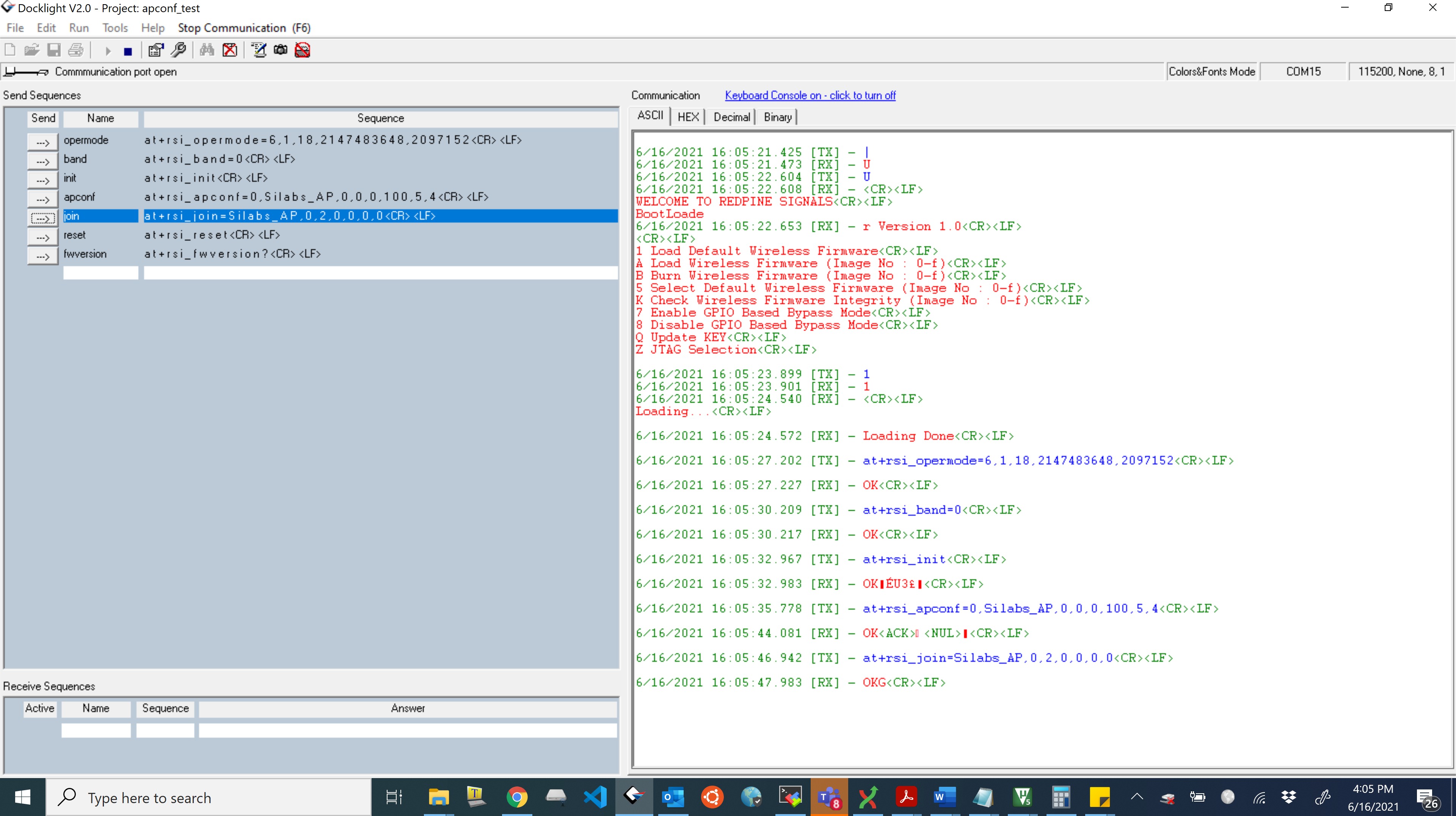

Note!
‘Authentication Required’ pop up window will only appear if BIT[23] in Custom feature bitmap is enabled. In that case opermode command should be at+rsi_opermode=6,1,18,2155872256,2097152\r\n Login credentials in case of ‘Authentication required’ : User Id : redpine password : admin
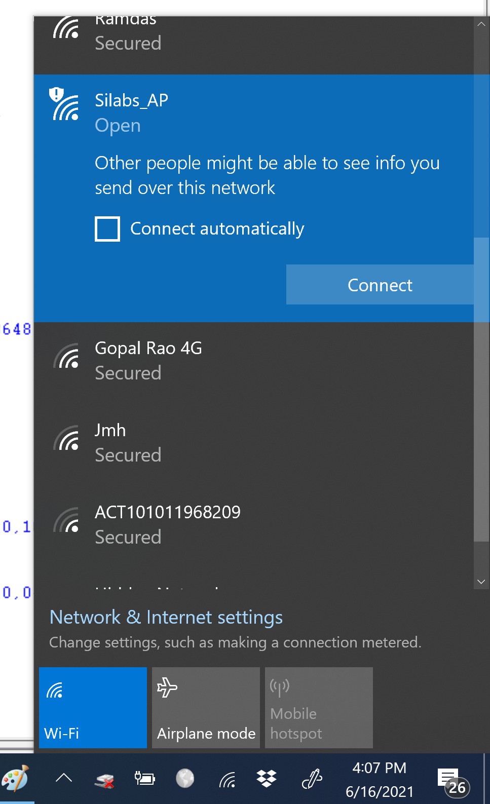
Connect to the Silabs_AP from a STA(in this example a laptop).

Open the AP configuration page by entering the IP address of the module in the browser.(in this case 192.168.100.76 by default).
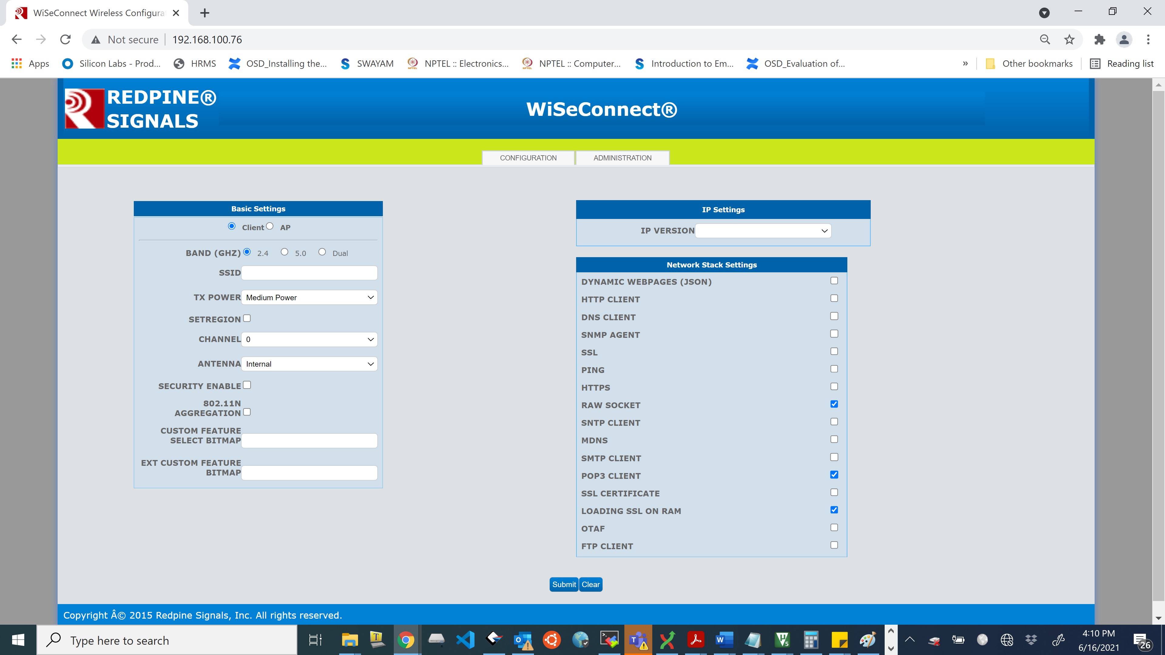

Click on Administration.
Choose a .rps file and click on upgrade.
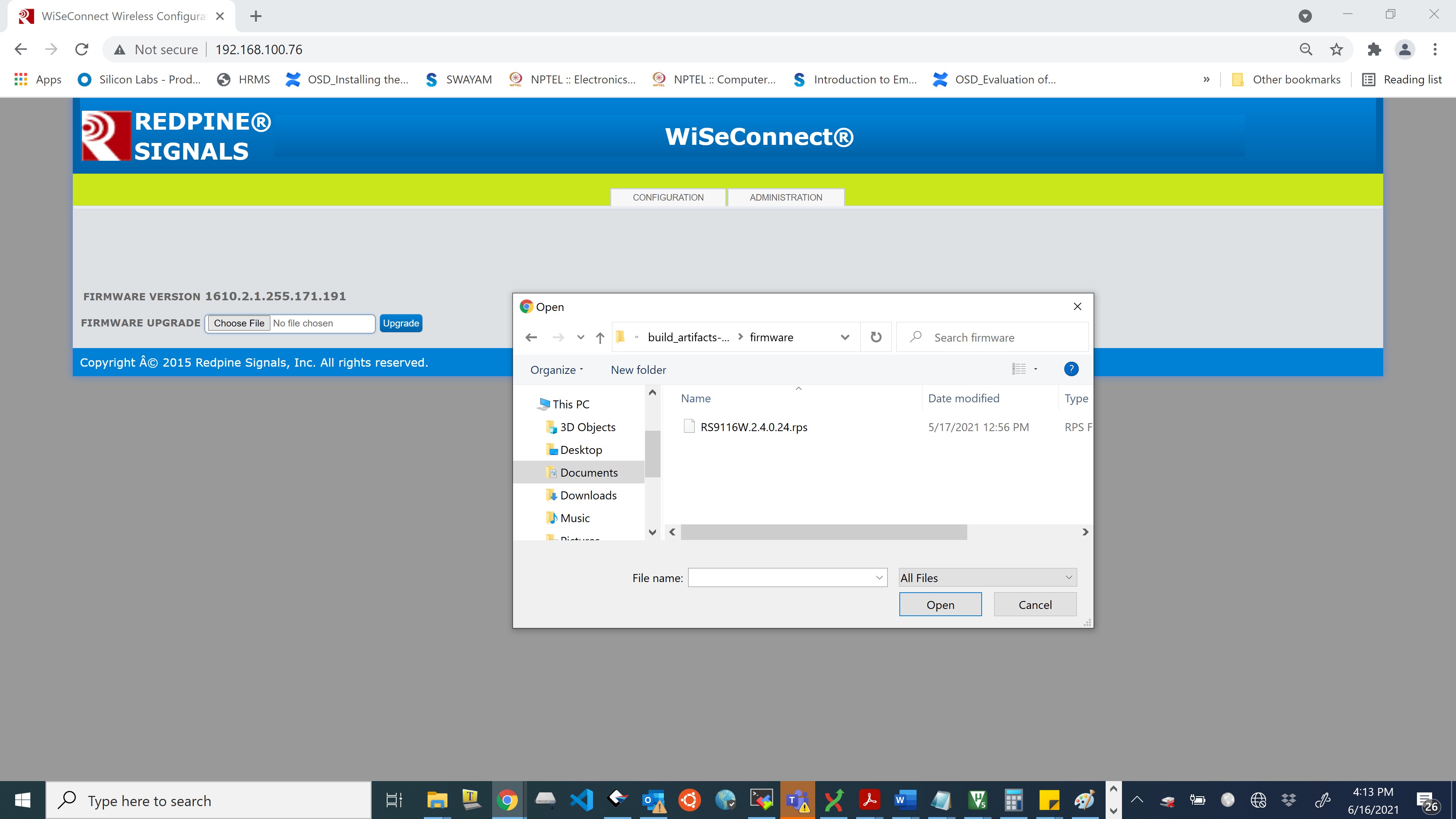

Upon clicking upgrade button on the webpage, host will get asynchronous notification
AT+RSI_FWUPREQ if it is connected to module through UART or USB-CDC interface.
So host has to issue the following command:
at+rsi_fwupokIf host failed to reply within specified timeout(~20 seconds), request will expire and upgradation process terminates.
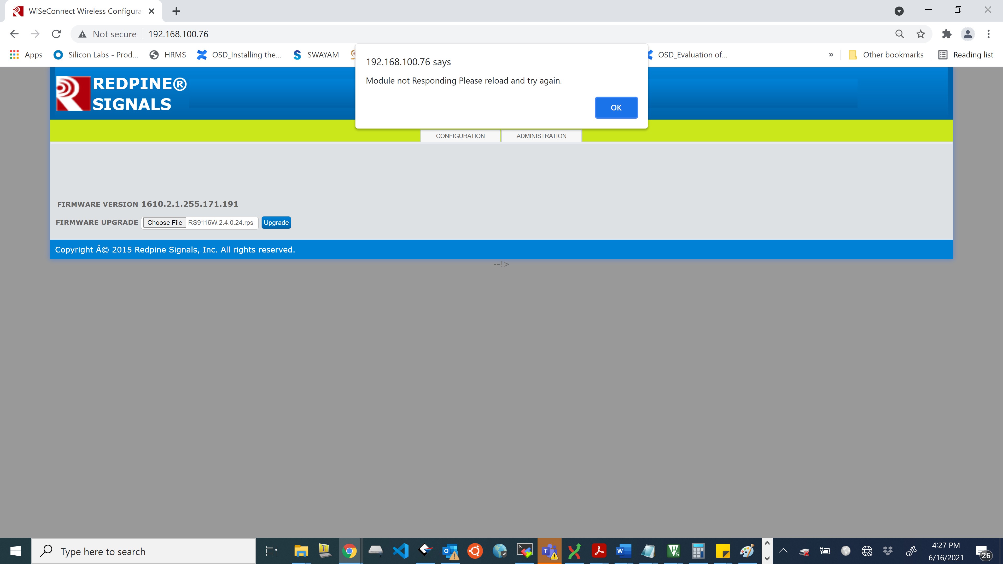

After the firmware upgradation is successful, a popup will appear on remote peer screen to intimate the process completion . An asynchronous success message
AT+RSI_FWUPSUCCESSis forwarded to the host connected with the module.
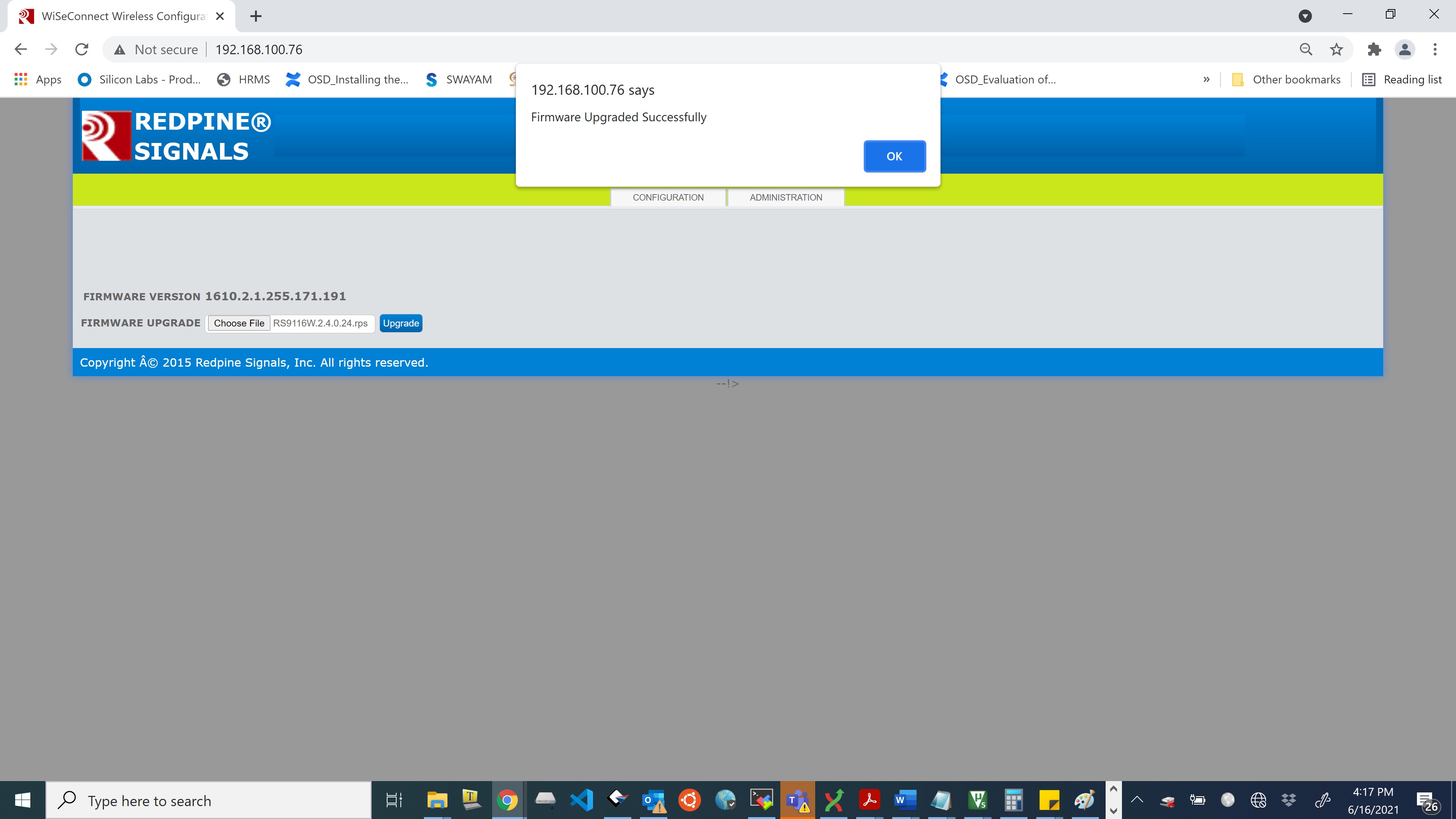

On firmware upgradation failure, there will be a pop-up on remote peer screen to intimate the process failure. Similarly, an asynchronous failure message
AT+RSI_FWUPFAILED(for UART/USB-CDC) will be forwarded to the host connected with the module.
Note!
Wireless firmware upgradation is supported only for the latest versions of Firefox and Google Chrome.
When the user clicks on the upgrade button, the module starts erasing flash for storing image. This may take few seconds, after this, upgradation will start automatically.
After wireless firmware upgrade, the user needs to wait for few minutes (~ 1.5 minutes) after reboot so that the bootloader will copy upgraded image into the actual flash location.
Firmware upgrade will fail if server(module) does not receive packets from the client (browser) within the timeout i.e., 40 seconds.
Firmware upgradation failed message will be received if server/client closes the TCP connection.
Wireless firmware upgradation is possible in client mode also. Enter the IP address of the module in browser to land on configuration page.
Storing Configuration From User#
This is an example sequence to store configuration from user.
at+rsi_opermode=0,1,4,0
at+rsi_band=1
at+rsi_init
at+rsi_usercfg=1294,payload in hex format>
Payload hex format#


Above command configures module with the values set by the user. The values set here are:
Parameter | Value |
|---|---|
| silabs |
| password |
| 0 |
| 1 |
| 4 |
| 0 |
| 1 |
| 1 |
| 192.168.1.2 |
| 0 (scans all channels) |
Note!
To configure more parameters, refer Store configuration structure parameters.
Parameters that are not required by the user can be configured as NULL values.
at+rsi_cfgenable=1This command enables auto-join or auto-create on power up. To check the configured parameters give:
at+rsi_cfgget?On power up, after bootloader options, immediately after the firmware is loaded you would receive OKC if the AP is available and the parameters are given correctly.
If you want to give new configuration, disable the current configuration using
at+rsi_cfgenable=0Use of dnsget with suppress_dns_response enable and tcp client connection#
 at+rsi_opermode=0,1,260,0

 This command sets the operating mode of the module.
at+rsi_band=0
This command sets the operating band of the module. at+rsi_init
This command initializes the module. at+rsi_scan=0,Silabs_AP
This command scans for APs and reports the APs found. at+rsi_psk=1,12345678
This command configures the PSK to be used to associate to the Access Point. at+rsi_join=Silabs_AP,0,2,2
This command associates the module to the AP. at+rsi_ipconf=1,0,0,0
This configures the IP address of the module in DHCP mode. at+rsi_dnsget=www.silabs.com,1,90
This command resolves IP of a given domain name and store resolved IP in the firmware. This info is cleared when the host issues another DNS query command or the STA disconnects from the AP. at+rsi_tcp=0.0.0.0,5001,5001,0,0,0,0,0,0,0,0,120,0,0,1
Opens a TCP client socket inside the module with port number 5001 and connects to the stored IP in the firmware.Use of dnsget with suppress_dns_response enable and store_server_ip_address with multiple socket connections#
at+rsi_opermode=0,1,260,0
This command sets the operating mode of the module.
 at+rsi_band=0

 This command sets the operating band of the module.
 at+rsi_init

 This command initializes the module.
 at+rsi_scan=0,Silabs_AP
 This command scans for APs and reports the APs found.
 at+rsi_psk=1,12345678
 This command configures the PSK to be used to associate to the Access Point.
 at+rsi_join=Silabs_AP,0,2,2
 This command associates the module to the AP.
 at+rsi_ipconf=1,0,0,0
 This configures the IP address of the module in DHCP mode.
 at+rsi_dnsget=www.silabs.com,1,90
 This command resolves IP of a given domain name and store resolved IP in the firmware. This info is cleared when the host issues another DNS query command or the STA disconnects from the AP.
 at+rsi_tcp=0.0.0.0,5001,5001,0,0,0,0,0,0,0,0,120,0,0,1
 Opens a TCP client socket inside the module with port number 5001 and connects to the stored IP in the firmware.
 at+rsi_store_server_ip_port=0,192.168.0.105,5003
 store server ip and port number in index 0.
 at+rsi_trans_mode_params=1024,+,50,50,50,4,0,5003,0,0.0.0.0,0,0,0,0,0
 This module enters trans_mode with specified paramete. Creates a client socket and connects to the server IP and port number stored in index 0.
Power Save in Coex mode#
at+rsi_opermode=851968,0,2147484806,2147483648,2150629376,3221225472,0,3760128000,2048This command sets the operating mode of the module.
at+rsi_feat_frame=0,1,0,0,1,49This command sets the correct RF type and path
at+rsi_band=0This command sets the operating band of the module.
at+rsi_initThis command initializes the module.
at+rsi_scan=0,SILABSThis command scans for the Access Points and reports the APs found.
at+rsi_psk=1,123456789This command configures the PSK to be used to associate to the Access Point.
at+rsi_join=SILABS,0,2,2,2,1000This command associates the module to the AP.
at+rsi_ipconf=1,0,0,0This configures the IP address of the module in DHCP mode.
at+rsibt_setadvertisedata=8,2,1,6,4,9,72,72,72This command is used to set the advertise data to expose remote devices.
at+rsibt_advertise=1,128,0,0,0,800,800,0,7This is used to expose or advertise about the local device to the remote BT devices.
at+rsi_pwmode=2,1This command configures the power save mode 2 in the module.
