Getting Started with a STM32 Host#
This guide describes how to get started developing a RS9116W application on an STM32 embedded host MCU using the WiSeConnect™ Simple Application Programming Interface (SAPI). For quick evaluation using only the EVK and a PC instead see Getting Started with PC using AT Commands.


Download the WiSeConnect™ Software Driver Package#
Download or clone the WiSeConnect™ Software Driver Package repository from GitHub.
Choose a host MCU development board and tools#
The example projects provided with the WiSeConnect™ Software Driver Package are designed to work out-of-the-box with the STM32F411RE Nucleo-64 Development Kit from ST Microelectroncis and the Keil MDK development environment. Before continuing with this guide, download and install the Keil MDK.
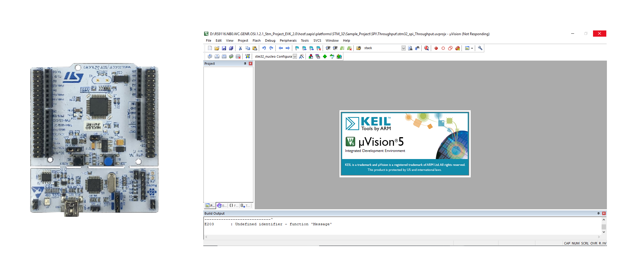

The WiSeConnect™ driver software can also be run on many other embedded host MCU's. To run example projects on a Silicon Labs EFM32/EFR32 host see: Getting Started with a EFx32 Host. Details on porting the driver to other non-Silicon Labs platforms can be found in the RS9116W SAPI Porting Guide.
Update the RS9116W Firmware#
When you first receive a RS9116 EVK or when upgrading to a new version of the WiSeConnect™ Software Driver Package, we recommend you update the RS9116W firmware. There are several update methods available when just getting started it is best to follow the method outlined in Updating RS9116W Firmware
Note! Be sure to disconnect the RS9116 EVK from the host MCU board before updating the firmware using the method described in Updating RS9116W Firmware
Connect the RS9116 EVK to the STM32 MCU Development Board#
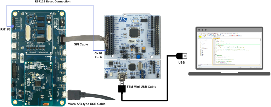
STEP 1. Connect the RS9116 EVK reset pin RST_PS to the STM32F11RE development board CN10 pin 6 to enable the STM32 to reset the RS9116.
STEP 2. Connect the STM32F411RE board to the SDIO/SPI connector of the RS9116 EVK using the 10-pin ribbon cable provided with the RS9116 EVK.

The pinout of the SPI cable is shown in the image below.
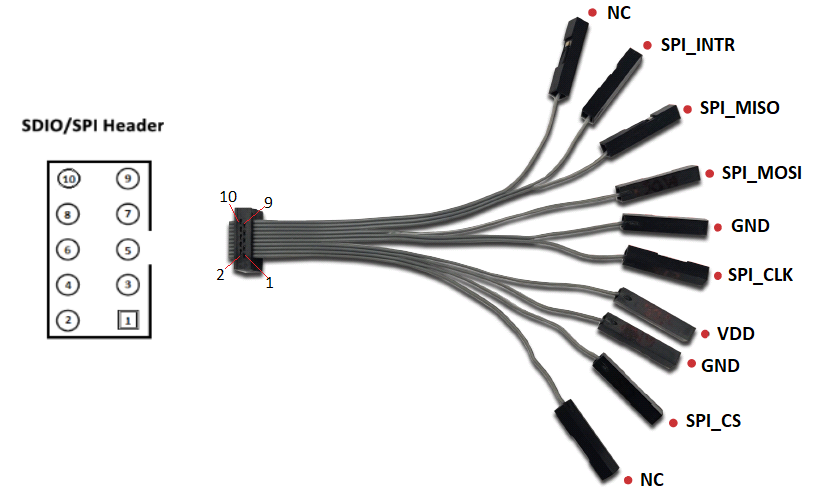

The following table summarizes the connections between the RS9116 EVK SDIO/SPI connector (J4) and the STM32F411RE development board connector (CN10).
Signal Name | RS9116 EVB (J4 - SDIO/SPI) | STM32F411 Board (CN10) |
|---|---|---|
|
| No Connect |
|
|
|
|
|
|
|
|
|
|
| No Connect |
|
|
|
|
|
|
|
|
|
|
|
|
|
| No Connect |
STEP 3. Set the ISP switch on the RS9116 EVK to the OFF position.
STEP 4. Connect the RS9116 EVK to a PC using the USB interface labeled POWER. Note that this connection only provides power to the EVK. There is no USB communication over this connection.
STEP 5. Connect the STM32 development board to a PC using the Mini USB connector on the STM32F411RE board.
Complete hardware details of the RS9116 EVK can be found in the RS9116 EVK User's Guide.
Power Save GPIO Connections#
The instructions above enable basic operation between the host MCU and RS9116. Some low power examples require additional GPIO configuration to enable Low Power (LP) or Ultra Low Power (ULP) operation. These details are valid for any example provided in the WiSeConnect™ SDK unless otherwise noted in the readme documentation for a particular example.
Connections for Ultra-Low Power (ULP) Operation
Signal Name | STM32F411 Board (CN10) | RS9116 EVK | Notes |
|---|---|---|---|
|
|
| |
|
|
| Only use |
Connections for Low Power (LP) Operation
Signal Name | STM32F411 Board (CN10) | RS9116 EVK | Notes |
|---|---|---|---|
|
|
| |
|
|
| Only use |
Reset Connection#
Signal Name | STM32F411 Board (CN10) | RS9116 EVK | Notes |
|---|---|---|---|
|
|
| An STM32 GPIO is used to reset the RS9116 |
Open an Example Project in the Keil IDE#
The WiSeConnect™ SDK includes a number of ready-made example projects for the STM32F411RE Nucleo-64 Development Kit and the Keil MDK development environment. A list of examples and documentation detailing the operation of each example can be found in: WiSeConnect™ Example Applications .
For the steps below, the Keil MDK development environment must be installed on the PC that is connected to the STM32F411RE development board. Refer to the Keil website for details on downloading and installing the development environment.
STEP 1. Open the Keil µVision IDE
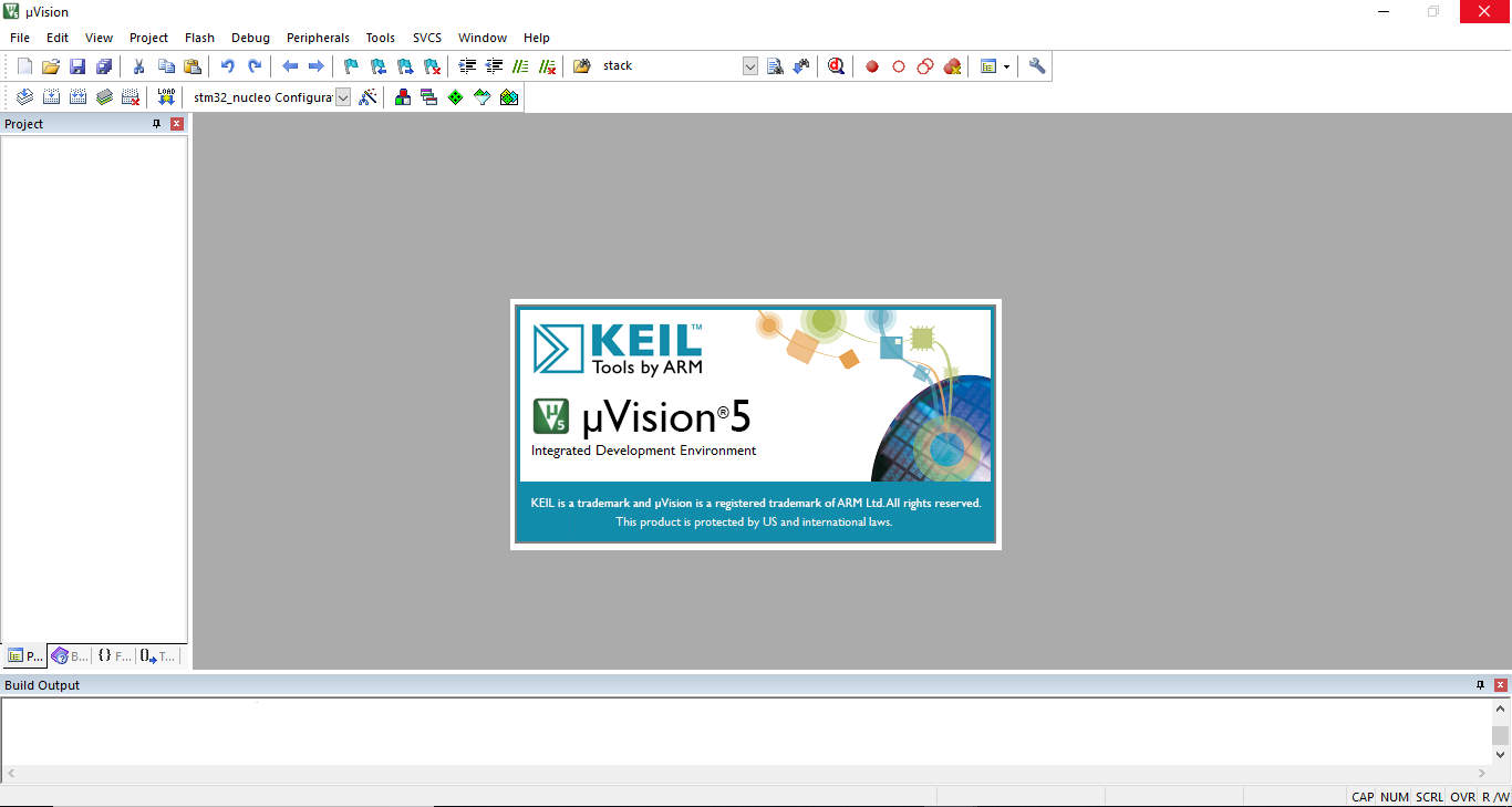

STEP 2. Click the menu item Project > Open Project...
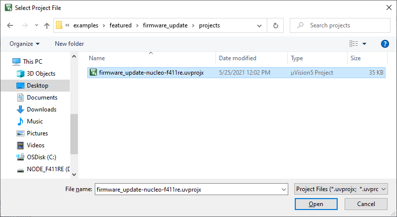
STEP 3. Navigate to the examples folder in the downloaded WiSeConnect™ Software Driver Package and choose the µVision project file of the example you would like to open. Every example contains a projects folder containing various project files. For example, the path to the firmware update featured example project can be found in the following path:
<SDK>/examples/featured/firmware_update/projects/firmware_update-nucleo-f411re.uvprojx.

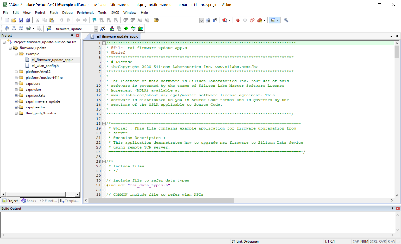
STEP 4. Opening the project will result in a fully functional project in the IDE that can be built, run and debugged.

Run an Example Project on the Development Kit#
You can build, run and debug the newly opened example project simply using the standard toolbar and menu items in the Keil µVision IDE. Refer to the Keil documentation for more details.
For instructions to configure and use each, see Example Applications. The same information is also available in the readme.md file available with the example project source code.
