Bluetooth LE Channel Sounding Fundamentals#
Introduction#
The determination of distance between two devices can be approached through a variety of methods, including the utilization of electromagnetic waves, ultrasonic waves, laser, infrared waves, and radio waves.
For radio wave-based distance estimation, several approaches exist. Among them, the commonly used approaches include:
Received Signal Strength Indicator (RSSI) based
Time based
Phase based
Existing Bluetooth LE (BLE) solutions such as real-time tracking, access control, and proximity based services heavily rely on distance estimation using an RSSI approach and/or Angle of Arrival (AoA) and Angle of Departure (AoD) technologies.
Channel Sounding#
Channel Sounding (CS) is a new feature introduced by the Bluetooth SIG for distance estimation between two Bluetooth LE devices. The standard employs both phase and time based approaches which are widely adopted in other wireless technologies. Using these approaches, and the optional multiple antenna support, the expected accuracy can be significantly higher than RSSI based measurements.
The standard defines 79 RF channels with 1 MHz separation for CS. Out of these, up to 72 channels are used for the actual transmission of CS tones and packets, while the rest are excluded due to overlap with primary advertising channels.
In CS, two peer devices, known as Initiator and Reflector, exchange information that is measured to produce a distance estimate between them. In CS, the Initiator transmits first, followed by the Reflector's response. A device supporting Bluetooth LE CS supports both the phase based and round-trip time measurement approaches explained below.
Distance Estimation Based on Phase-Based Ranging (PBR)#
The Phase-Based Ranging (PBR) approach works based on the principle that the phase shift introduced by a pure line of sight radio channel on a signal is a linear function of the distance
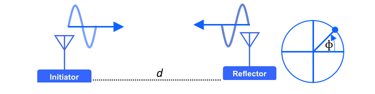
Phase-Based Ranging (PBR)#
For a radio wave with period
Equation 1
Where
Equation 2
Replacing
Equation 3
For a round trip distance
Equation 4
Phase measurement is circular, meaning that it wraps around 2
Equation 5
Rearranging eq. 5, distance is:
Equation 6
Due to phase wrapping, round trip distance measurements are only unambiguous within half-wavelength distance. In practice, though, we want to measure longer distances than that.
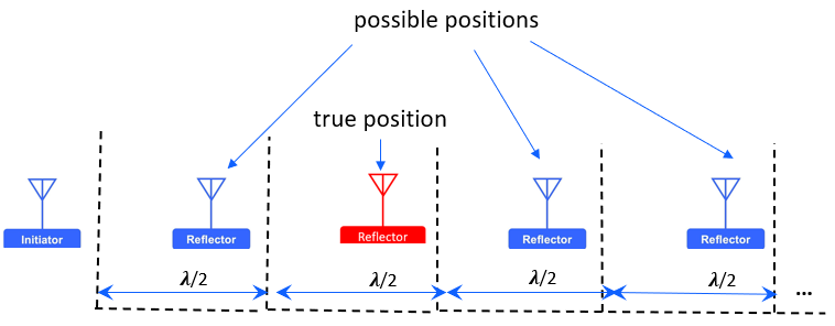
Distance Ambiguity Due to Phase Wrapping#
To unwrap the phase and estimate distance without ambiguity, the phase shift can be measured at two or more distinct tones [1].
Equation 7
Equation 8
Combining eq. 7 and 8, the spatial distance measured using the two tones can be represented as:
Equation 9
From eq. 9, the distance wrap or the maximum distance that can be measured using multiple tones PBR, can be determined as follows, where
Equation 10
With a
Eliminating Local Oscillator Phase Offset#
Note that the Reflector device does not have to lock the Local Oscillator (LO) to the incoming signal and transmit back to the Initiator. By keeping the LOs on between TX/RX, exchanging tones and doing two-way phase difference measurements, the unknown initial phases of the LOs can be canceled out, and the spatial phase rotation can be measured.
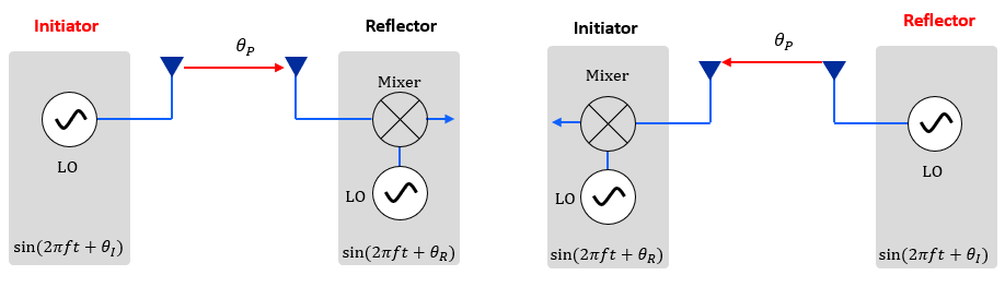
Local Oscillator Phase Offset#
Let Phase Correction Term (PCT) be defined by the angle, if added to the internal angle of the LO, would result in a phase identical to that of the incoming signal. Then, the measured phase at the Reflector is:
Equation 11
Similarly, the measured phase at the Initiator side is:
Equation 12
The round trip phase rotation is then:
Equation 13
Distance Estimation Based on Round-Trip Time (RTT)#
The Round-Trip Time (RTT) approach allows distance estimation by measuring the round trip propagation delay. Given the same time base on both devices, sufficient precision of Time of Departure (ToD) and Time of Arrival (ToA) for the required distance accuracy, and under ideal line of sight conditions, then the distance
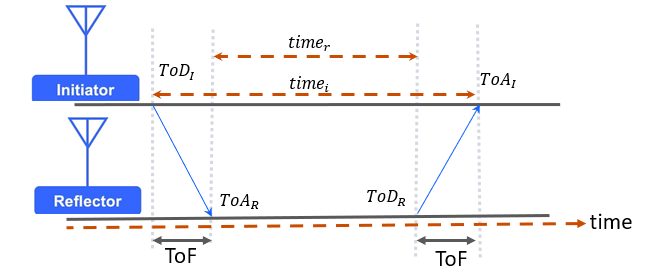
Round-Trip Time Based Ranging (RTT)#
Equation 14
Equation 15
Where:
is the round-trip time is speed of light is Time of Arrival at the Reflector is Time of Departure at the Initiator is Time of Arrival at the Initiator is Time of Departure at the Reflector
Bluetooth Channel Sounding Procedure#
Bluetooth CS procedure consists of a series of radio operations in which the Initiator and Reflector devices exchange information that is used to either calibrate each other or measure distance between them.
For a CS procedure to start, the peer devices must first form an encrypted connection. Once an encrypted connection is in place, the CS is configured and security information is exchanged, after which the CS procedure can begin.
A CS procedure can be divided into one or more CS events. A CS procedure (and hence the first CS event in a CS procedure) is started CS offset from the timing of Asynchronous Connection-oriented Logical (ACL) connection event anchor point. A CS event may contain one or more subevents. A CS subevent on its turn may contain two or more CS steps. The figure below shows the relationship between CS procedures, CS events, CS subevents, and CS steps.
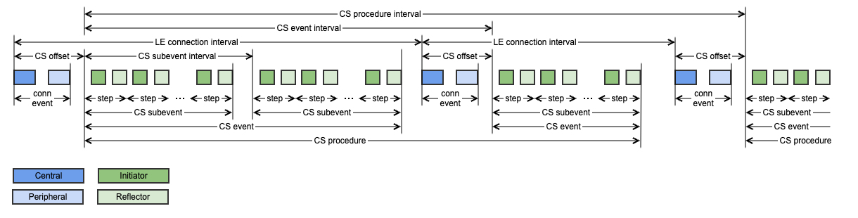
CS Procedure#
It is important to note that the BLE connection roles of the devices are not strictly tied to CS roles, which allows both central and peripheral devices to assume either the Initiator or Reflector role. In the above figure, it is assumed that the central device is the Initiator and the peripheral device is the Reflector.
In a CS step, bilateral exchange between the peer devices occurs. In each step, the Initiator transmits first and the Reflector responds with one or more transmissions. These transmissions may be GFSK modulated packets, or ASK modulated tones, or both. After receiving the packets, tones, or both from the other peer device, the devices do time and/or phase measurements on their own. One of the devices sends back its measured data over a Bluetooth connection using the Ranging Service (RAS) GATT to the peer device, which then determines the actual distance estimate. Note, however, that the determination of distance measurements is outside the scope of the Bluetooth Channel Sounding specification.
CS steps require a precise timing synchronization between the Initiator and Reflector devices. Between the CS steps there is a time separation defined as T_FCS to allow frequency hopping. Refer to the core specification for the permitted values of T_FCS.

The spec defines four CS step mode types, each designated for a specific purpose as detailed below.
Mode-0 Steps#
CS step mode-0 CS is used to measure and calibrate the frequency offset between the Initiator and Reflector at a given frequency.
Each subevent in a CS procedure begins with one to three mode-0 steps to provide calibration information for the remaining CS steps within that subevent. Based on the mode-0 step results, the Fractional Frequency Offset (FFO) is calculated which will be used by the Initiator device to align the timing of CS steps and transmit frequencies during non-mode 0 CS steps.
The structure of CS step mode-0 is depicted as follow.

CS step mode-0#
* CS_SYNC_0_I is a CS SYNC packet sent from the Initiator to the Reflector during mode-0 steps.
** CS_SYNC_0_R is extended packet—CS SYNC followed by CS Tone sent by the Reflector to the Initiator during mode-0 steps.
For additional information on CS SYNC and CS extended packet formats, refer to Channel Sounding Packet Formats.
T_SY is the duration of the CS SYNC packet which depends on the PHY used.
T_RD is ramp-down time in which the transmitter is allowed to remove the transmitted energy from the RF channel. It's value is
T_IP1 is the idle time between the end of transmission from the Initiator and the start of the transmission from the Reflector. Please refer to the core specification for the permitted values of T_IP1.
T_FM is the duration of the frequency measurement; and it's value is
Mode-1 Steps#
Mode-1 step is used to measure the round-trip time between the intiator and the Reflector. The structure of step mode-1 is depicted below.
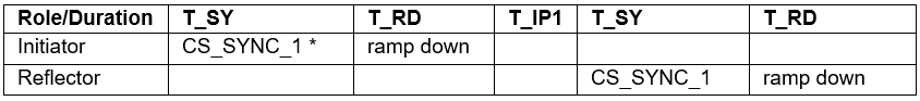
CS step mode-1#
* CS_SYNC_1 is a CS SYNC packet exchanged between the Initiator and Reflector during step mode-1. For additional information on CS SYNC packet format, refer to Channel Sounding Packet Formats.
The duration of T_SY in step mode-1 depends on the PHY used and the use of the optional Sounding Sequence or Random Sequence bits described in Channel Sounding Packet Formats.
Mode-2 Steps#
Mode-2 step is used to measure the phase rotation of the RF signal between the Initiator and the Reflector. The structure of mode-2 step is depicted as follow.

CS step mode-2#
* CS tone is Amplitude Shift Keying (ASK) modulated continuous carrier wave.
T_SW is antenna switching duration.
T_PM is the phase measurement period. Please refer to the core specification for the permitted values of T_PM.
T_IP2 is the idle time between the end of transmission from the Initiator and the transmission from the Reflector. Refer to the core specification for the permitted values of T_IP2.
N_AP is the number of antenna paths.
Mode-3 Steps#
Mode-3 step is used to measure the phase rotation of the RF signal and the round-trip time between the Initiator and the Reflector. The structure of mode-3 step is depicted as follow.
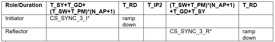
CS step mode-3#
* CS_SYNC_3_I is extended packet—CS SYNC followed by CS Tone sent by the Initiator to the Reflector.
** CS_SYNC_3_R is extended packet—CS Tone followed by CS SYNC sent by the Reflector to the Initiator. For additional information on the extended packet format, see the next section, Channel Sounding Packet Formats.
Note that the specification requires the implementation of mode-0, mode-1, and mode-2 steps as mandatory. Mode-3, however, is optional.
Channel Sounding Packet Format#
In general, there are three packet formats defined in channel sounding:
CS SYNC
Extended packet—CS SYNC followed by CS Tone
Extended packet—CS Tone followed by CS SYNC
CS SYNC Packet#
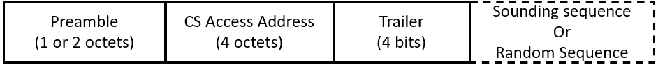
CS SYNC is a specific modulated bit sequence defined for CS. The packet format of CS SYNC is similar to that of LE Uncoded PHY, except that CS SYNC packet has no PDU, CRC or CTE fields. The contents of CS SYNC packet format are shown in the following figure.
The duration of a CS SYNC packet with no Sounding Sequence or Random Sequence fields is
The mode-0 CS SYNC packets are sent without the optional Random Sequence or Sounding Sequence.
Preamble#
The same rules defined for the preamble of the LE uncoded PHY packet format applies to the preamble of CS SYNC packet. The length of the preamble is 1 octet when using 1M PHY, and 2 octets when using 2M PHY.
CS Access Address#
CS Access Addresses are used for synchronization, security, and round-trip time purposes. Each CS Access Address is a sequence of bits that is cryptographically generated using a dedicated CS Deterministic Random Bit Generator (DRBG).
Trailer#
The CS trailer is a sequence of 4 bits alternating between 0 and 1 bits. The trailer sequence is 1010 when the most significant bit of the Access Address is 0; otherwise, it is 0101.
Sounding Sequence#
Sounding Sequence is an optional feature that can be either 32 or 96 bits long. If present, one or more 4-bits long marker signals are added to the sounding sequence for resilience against spoofing attacks.
Random Sequence#
Random Sequence is also an optional feature that can be 32, 64, 96, or 128 bits long.
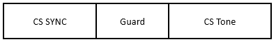
Extended Packet—CS SYNC followed by CS Tone#
This packet format has two mode-specific variations:
CS_SYNC_0_R: transmitted by the Reflector in CS step mode-0.
CS_SYNC_3_I: transmitted by the Initiator in CS step mode-3.
Extended Packet—CS Tone followed by CS SYNC#
The occurrence of this packet format is during CS_SYNC_3_R, i.e packet transmission from Reflector to Initiator in mode-3.
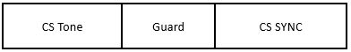
In both extended packet formats, the CS tone and CS SYNC are transmitted on thcs e same RF frequency.
In both extended packet formats, the duration of the guard time T_GD is
Channel Sounding Security#
CS has included various security features to detect and reduce the probability of distance spoofing. The table below summarizes the different types of vulnerabilities associated with proximity-based services and the corresponding mitigation approaches that CS provides.
Vulnerability | Description |
|---|---|
Impersonation attack: an attacker attempts to break the authentication by impersonating the legitimate transceivers. | This kind of attacks can be prevented using good cryptography and a state-of-the-art authentication/signature protocols. In CS, data exchange between Initiator and Reflector devices occurs on an encrypted connection. CS uses DRBG to randomize CS Access Address, channel list order, sounding sequence marker and marker position in CS SYNC packets, tone extension slot present information, etc. A CS device returns CS Access Address quality indication value for CS_SYNC packet received in a CS step. This information can be used for security measures. |
Range extender attacks: an attacker amplifies the signal without altering the phase or frequency, making the devices appear closer to each other than they actually are. | PBR based measurement cannot prevent this kind of attack since an attacker can amplify or relay the signal beyond the ambiguity range. However, ToF measurement (i.e RTT approach) can prevent such attacks since time does not roll over. CS allows for the use of RTT and PBR ranging in the same subevent, or in the same step (i.e mode-3) to obtain two partially independent distance estimates. The discrepancy between the RTT and PBR measurement results can be used by the application for security measures. |
Phase manipulation attack: an adversary manipulates the phase of the constant tone signal to reduce the estimated distance. | This kind of attack only affects phase and not the time. Thus, RTT can be used with PBR to provide additional security layer to detect this kind of attacks. |
Early Detect Late Commit (EDLC): an attacker aims at decreasing the ToF, for instance, by detecting a bit in a symbol and predicting the symbol even before receiving it completely. | This kind of attack affects GFSK modulated packets, i.e mode-0, mode-1 and mode-3. As such, PBR can offer protection against such attacks within the ambiguity range. CS step mode-1 and mode-3 allow sending CS SYNC packets with an optional Sounding sequences or Random Sequence, which can provide capabilities to potentially detect whether an attacker is present. Using Random sequences, it is possible to measure how much a received GFSK modulated packet signal differs from the expected packet signal. Using Sounding sequence, it is possible to detect the position of one or more marker signals. In Addition, CS introduces Normalized Attack Detector Metric (NADM), which provides a measure of how much a received GFSK modulated packet signal differs from the expected packet. Please refer to the core specification to learn more about NADM values and their corresponding indications for the likelihood of attacks. |
References#
[1] Zand, Pouria, et al. "A high-accuracy phase-based ranging solution with Bluetooth Low Energy (BLE)." 2019 IEEE wireless communications and networking conference (WCNC). IEEE, 2019.
[2]. Bluetooth Channel Sounding Draft Specification: https://www.bluetooth.com/specifications/specs/channel-sounding-cr-pr/.
[3]. White paper: Distance Bounding Protocol for Bluetooth Secure Access: https://www.imec-int.com/en/expertise/sensors-for-iot/secure-system-solutions/distance-bounding-white-paper.