Introduction to the RS9116 nLink Driver#
The RS9116N Open Source Driver (OSD) is a SoftMAC driver that interacts with the Linux wireless MAC layer i.e., MAC80211. The driver is a group of simple and efficient kernel modules which currently supports RS9116N chipsets and can be ported to any embedded platform in-addition to X-86 platform. It supports the following protocols:
Wi-Fi (Client and Access Point mode)
Bluetooth Classic
Bluetooth Low Energy
It supports the following protocol combinations :
WLAN STATION
WLAN ACCESS POINT
BT CLASSIC MODE
BT LE MODE
WLAN STATION + BT CLASSIC MODE
WLAN STATION + BT LE MODE
BT CLASSIC + BT LE MODE
WLAN STATION + BT CLASSIC MODE + BT LE MODE
WLAN ACCESS POINT + BT CLASSIC MODE
WLAN ACCESS POINT + BT LE MODE
WLAN ACCESS POINT + BT CLASSIC MODE + BT LE MODE
The following sections will guide the user on usage of the driver.
Getting Started with the RS9116 nLink Driver#
This section lists the hardware and software requirements for the installation of the software and describes the steps to be followed to initialize and run the software.
Hardware Requirements#
The hardware requirements are as follows:
RS9116N n-Link® Module
Laptop/PC with SDIO or USB interface or any embedded platform with Linux Board support package.
Note: If the Laptop/PC does not have an SDIO slot, a SDHC/SD/MMC to CardBus Adapter like the one available athttp://www.hwtools.net/cardreader/SDCBA_C01.html can be used.
Software Requirements#
The software requirements are as follows:
Supported Linux Kernel Versions are mentioned in ReleaseNotes.pdf file – should enable the open source SDIO and USB stacks.
DHCP Server (for Wi-Fi Access Point mode)
Bluetooth supported commands bluetoothctl and bluetoothd must be present
Compatible Bluetooth Host Stack, e.g., the Open Source BlueZ Stack v4.10
wpa_supplicant (for Wi-Fi Client mode)
hostapd (for Wi-Fi Access Point mode)
Software Package Contents#
The driver package is delivered in the format: RS911X-nLink-OSD-master.zip, where the naming convention is as follows:
The driver package contains the following files/folders:
Readme.txt
ReleaseNotes.pdf
Firmware
rsi (contains driver source code)
scripts
The drivers can be found under each Product on our website: RS9116 Open source driver .
Compilation Steps#
This section describes the steps to be followed to compile the driver for different platforms. The steps are outlined below:
Extract the package using the following command:
# unzip RS911X-nLink-OSD-master.zipGo to the package and copy all the files present in Firmware folder to '/lib/firmware' by following the below commands.
   # cd RS911X-nLink-OSD-master
   # cp Firmware/* /lib/firmware
There are two ways in which you can build the driver.
Build from the local path
Build from kernel source
Building the Driver from the Local Path#
Configure build flags in driver source.
# cd rsiOpen Makefile and configure build flags. Below are the build flags to be set based on the usage of driver. Selecting the required options shall reduce the binary size which is important for kernel modules particularly on embedded platforms.
KERNELDIR : Provide the kernel source path here. For example on X-86 below path is used.
KERNELRELEASE=$(Shell uname -r)
KERNELDIR=/lib/modules/$(KERNELRELEASE)/build
CONFIG_RSI_COEX_MODE : Enable this flag when Wi-Fi and BT coexistence mode is used.
CONFIG_RSI_DEBUGFS : Debugfs is used by driver to take dynamic configuration from user. Supported debugfs based configurations are listed in the corresponding feature sections in TRM.
CONFIG_RSI_BT_ALONE : Enable this flag when only BT EDR/ BT LE only mode is used.
Build the driver using make command.
# make
For embedded platforms, add the Kernel path for target platform and toolchain path as cross compilation option to the "make" command.
For example, if the target platform is iMX6 add the kernel path as below :
KERNELDIR=home/test/Wand/armv7-multiplatform/KERNEL For example, if the target platform is ARM and tool chain path is "/opt/freescale/usr/local/gcc-4.4.4-glibc-2.11.1-multilib-1.0/arm-fsl-linux-gnueabi/bin/arm-none-linux-gnueabi-", then the command is issued as:
# make ARCH=arm CROSS_COMPILE=/opt/freescale/usr/local/gcc-4.4.4-glibc-2.11.1-multilib-1.0/arm-fsl-linux-gnueabi/bin/arm-none-linux-gnueabi- Building the Driver from Kernel Source#
Copy the driver 'rsi' to <kernel_source_path> /drivers/net/wireless.
(Ex : linux-5.7.0/drivers/net/wireless/rsi )
Go to rsi directory and move Makefile to Makefile_local.
# mv Makefile Makefile_localMove Makefile_ker to Makefile.
# mv Makefile_ker MakefileGive 'make menuconfig' from kernel source directory. (Ex : linux-5.7.0 )
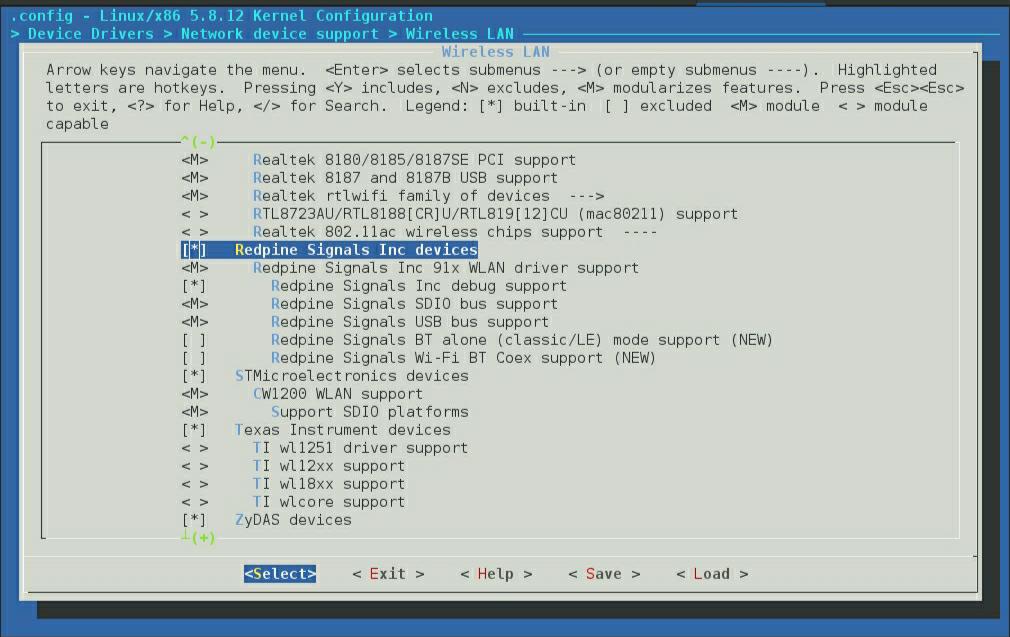
# make menuconfigGo to 'Device Drivers->Network device support->Wireless LAN'.
Select 'Redpine Signals Inc' devices.
Select the SDIO/USB bus support depending on requirement. You will see the below screen with all the build options mentioned above. Select the required options.
Build driver by using the below commands:
# make M=drivers/net/wireless/rsi
On successful compilation, make will generate rsi_91x.ko , rsi_usb.ko and/or rsi_sdio.ko according to the configuration.
In the next section, Installing the nLink Driver process is given in detailed step-by-step instructions.
Installing the nLink Driver#
Installation of Modules#
After a successful compilation, the driver generates the following modules in the rsi folder according to the configuration. They are outlined below:
rsi_91x.ko
rsi_usb.ko
rsi_sdio.ko
To install the driver, use the following commands:
1. Before installing driver install the dependencies using below commands#
   #modprobe mac80211
   #modprobe cfg80211
   #modprobe bluetooth
2. Insert rsi_91x.ko with the required module params (configuration) as shown below#
#insmod rsi_91x.ko dev_oper_mode=<mode> rsi_zone_enabled=<val> ... Module params are used by the driver to take initial configuration required. If not provided, default configuration is used. For most of the applications, default values of these module params will be sufficient. Supported module params with their configurable limits are explained in this TRM in respective feature sections and/or refer
Appendix B:Initial Configuration Parameters
In the above command example, module param rsi_zone_enabled is to enable debug prints in dmesg. Default value of rsi_zone_enabled value is 1, which prints errors (only) in terminal. Please refer Appendix A: Driver Details , to enable more debug prints.
dev_oper_mode : Device operating mode indicates the possible combination of the wireless protocols that can configured with the device.
The table below provides the operating mode details with its constraints.
S.No | Operating Mode | Protocol Support | Maximum No. of Clients for WLAN AP | Maximum No. of BT Connections | Maximum No. of BLE Connections | ||||
|---|---|---|---|---|---|---|---|---|---|
STA | AP | BT EDR | BT LE | ||||||
1 | 1 | √ | X | X | X | N/A | N/A | N/A | |
2 | 1 | X | √ | X | X | 16 clients | N/A | N/A | |
3 | 1 | √ | √ | X | X | 4 clients | N/A | N/A | |
4 | 4 | X | X | √ | X | N/A | 2 | N/A | |
5 | 5 | √ | X | √ | X | N/A | 2 | N/A | |
6 | 6 | X | √ | √ | X | 16 clients | 2 | N/A | |
7 | 8 | X | X | X | √ | N/A | N/A | 3 (Can be as Main for 2 Secondary connections Or Can be as Main for one Secondary connection and can connect to other Main as Secondary) | |
8 | 9 | √ | X | X | √ | N/A | N/A | 3 | |
9 | 10 | X | √ | X | √ | 16 clients | N/A | 3 | |
10 | 12 | X | X | √ | √ | N/A | 2 | 3 | |
11 | 13 | √ | X | √ | √ | N/A | 2 | 3 | |
12 | 14 | X | √ | √ | √ | 4 clients | 2 | 3 |
If any invalid mode is passed to the module, driver returns error and exit. You can check the error message debug logs.
Note:
For modes 4 ,8 and 12 build flag CONFIG_RSI_BT_ALONE should be enabled in the driver Makefile.
For modes 5, 9, 6,13 and 14, build flag CONFIG_RSI_COEX_MODE should be enabled in the driver Makefile.
3. For the USB interface, enter the command below#
#insmod rsi_usb.ko 4. For the SDIO interface, enter the command below#
   #insmod rsi_sdio.ko sdio_clock=<clk_val>

Note: Here “clk_val” is 1 to 50 (in MHz’s).
You can install either USB or SDIO or both depending upon the selection of the interface.
After a successful installation, a new wireless interface shall be created or WLAN and/or BT/BLE as per the dev_oper_mode selection.
a. If WLAN is selected, interface details can be verified using the commands below.
Name of the Wi-Fi interface created after successful installation of the driver can be seen using 'ifconfig' command.
# ifconfig -a You should expect an output like the sample shown below with all other available interfaces included.
   wlan0  flags=4163<UP,BROADCAST,RUNNING,MULTICAST> mtu 1500
   inet6 fe80::8da:1aff:fe1e:d1c8  prefixlen 64 scopeid 0x20<link>
   ether 88:da:1a:1e:d1:c8  txqueuelen 1000  (Ethernet)
   RX packets: 3 bytes 372 (372.0 B)
   RX errors 0 dropped 0 overruns 0 frame 0
   TX packets: 6 bytes 696 (696.0 B)
   TX errors 0 dropped 0 overruns 0 collisions:0
Also, for WLAN, there is another utility (iw) with which you can get the interface and physical device details. For example, the command below will show the interface status and physical device number.
# iw dev <interface_name> info The sample output for this command is shown below.
Interface wlan0
  ifindex 5
  wdev 0x100000001
  addr 00:23:a7:b9:ab:44
  type managed
  wiphy 1 channel 6 (2437 MHz), width: 20 MHz (no HT), center1: 2437 MHz
As can be seen, in this case, phy<X> is termed as wiphy 1.
b. If BT/BLE is selected, interface details can be verified using below command.
Name of the BT/BLE interface created after successful installation of the driver can be seen using 'hciconfig' command.
  # hciconfig -a

   hci0:  Type: BR/EDR  Bus: USB
   BD Address: 88:DA:1A:00:00:C2  ACL MTU: 1021:3  SCO MTU: 64:3
   UP RUNNING
   RX bytes:1006 acl:0 sco:0 events:55 errors:0
   TX bytes:0 acl:0 sco:0 commands:55 errors:0
   Features: 0xbf 0xfe 0x0d 0xfe 0xdb 0xff 0x5b 0x87
   Packet type: DM1 DM3 DM5 DH1 DH3 DH5 HV1 HV2 HV3
   Link policy: RSWITCH SNIFF
   Link mode: SECONDARY ACCEPT
   Name: 'lapt64'
   class: 0x0c010c
   service Classes: Computer, Laptop
   HCI Version:  (0x9) Revision: 0x0
   Manufacturer: internal use (65535)
Installation in Wi-Fi Only Mode#
Wi-Fi Station Mode#
This section provides the steps to configure Wi-Fi station mode using both wpa_supplicant and the Network Manager CLI. Both procedures are given below. The user can choose any method.
Before installation, the user needs to stop the existing network manager and unblock WLAN from rfkill. The commands below are used to stop the network-manager on different Linux distribution.
For Ubuntu, use the following command.
# service network-manager stopFor Fedora, use the following command.
# service NetworkManager stopTo stop rfkill blocking WLAN, use the following command.
# rfkill unblock wlan (or) #rfkill unblock all
For station mode connectivity, ensure that the dev_oper_mode is set in installation as given below and interface is detected after the installation (Refer to the Installation of Modules section).
dev_oper_mode = 1
Configure Station Using WPA_supplicant#
a) Create a sta_settings.conf file with the information below. Also, fill the information like ssid, psk etc corresponding to the AP you intend to connect in this file. Sample sta_settings.conf file is available within scripts directory of release package with basic configurations required. The user may use this file and edit the information as explained below. For the details of all configurations available please refer to the open source supplicant wpa_supplicant.conf file.
   ctrl_interface=/var/run/wpa_supplicant
   update_config=1
Also, add network block to the sta_settings.conf file as per the AP security. An example network block for different security modes is listed below.
i. For Open (non-Secure) mode:
   network={
   ssid="\<SSID of Access Point\>"
   key_mgmt=NONE
   priority=3
   }
ii. For WPA2-PSK (CCMP) mode:
   network={
   ssid="\<SSID of Access Point\>"
   key_mgmt=WPA-PSK
   psk=\<passphrase specified in the Access Point\>
   proto=WPA2
   pairwise=CCMP
   group=CCMP
   }
The pass phrase can be input either in ASCII or Hexadecimal formats:
ASCII Format: psk="very secret passphrase"
Hexadecimal Format: psk=06b4be19da289f475aa46a33cb793029d4ab3db7a23ee92382eb0106c7
iii. For WPA3 security mode:
To connect in WPA3, we need to compile the latest supplicant with below flags enabled in wpa_supplicant .config file
CONFIG_SAE=y
CONFIG_IEEE80211W=y
pmf=2
   network={
   ssid="\<SSID of Access Point\>"
   key_mgmt=SAE
   psk=\<passphrase specified in the Access Point\>
   ieee80211w=2
   }
Note: WPA3 Enterprise security mode is not supported in this release.
iv. For WPA2-EAP TLS (Enterprise mode) mode:
   network={
          ssid="\<SSID of Access Point\>"
          key_mgmt=WPA-EAP
          eap=TLS
          anonymous_identity="tlsuser"
          identity="test"
          password=\<passphrase specified in the Access Point\>
          ca_cert="/etc/certs/wifiuser.pem"
          client_cert="/etc/certs/wifiuser.pem"
          private_key_passwd=\<private key password\>
          private_key="/etc/certs/wifiuser.key"
          pairwise=CCMP TKIP
          group=CCMP TKIP
          proto=WPA2 WPA
          priority=20<br>
          }
In EAP-TLS user has to copy client certificates in a path and the path need to be configured in network block as given above.
v. For WPA2-EAP PEAP (Enterprise mode) mode:
   network={
          ssid="\<SSID of Access Point\>"
          key_mgmt=WPA-EAP
          eap=PEAP
          anonymous_identity="peapuser"
          identity="test"
          password=\<passphrase specified in the Access Point\>
          pairwise=CCMP TKIP
          group=CCMP TKIP
          proto=WPA2 WPA
          priority=20
          }
vi. For WPA2-EAP TTLS (Enterprise mode) mode:
   network={
          ssid="\<SSID of Access Point\>"
          key_mgmt=WPA-EAP
          eap=TTLS
          anonymous_identity="ttlsuser"
          identity="test"
          password=\<passphrase specified in the Access Point\>
          pairwise=CCMP TKIP
          group=CCMP TKIP
          proto=WPA2 WPA
          priority=20
          }
To connect to an Access Point whose SSID is not broadcast (Hidden), add the following line to the network block.
scan_ssid=1 For example :
   network={
          ssid="\<SSID of Access Point\>"
          scan_ssid=1
          key_mgmt=NONE
          }
For Selective Scan:
To enable selective scan , Add freq_list parameter outside the network block . freq_list is Space-separated list of frequencies in MHz which limits the frequencies that will be scanned.
freq_list=2412 2437 2462 Example config file that will only scan on channel 1 and 36.
   freq_list=2412 5180
   network={
          ssid="\<SSID of Access Point\>"
          key_mgmt=NONE
          }
b) Start the supplicant using below command:
# wpa_supplicant -i <interface_name> -D nl80211 –c sta_settings.conf –dddt > supp.log & For example :
# wpa_supplicant -i wifi0 -D nl80211 –c sta_settings.conf –dddt > supp.log &"–i" option specifies the Wi-Fi interface name
<interface_name> - This name as listed in iw dev output (here wifi0)
"-D" specifies the driver interface to be used. In open source driver it is nl80211.
"-c" specifies the supplicant configuration file.
"-d" specifies the log level of supplicant. You can apend more d's to it for more detailed logs.
c) To check the scan results please use below command.
# wpa_cli -i <interface_name> scan_resultsFor example, above command will give scan results output as follows.
   bssid         / frequency   / signal level    /  flags/ ssid
   50:d4:f7:1e:5a:40   2457           -21  [WPA2-PSK-CCMP][ESS]    TP_LINK
   04:79:70:72:03:e7   2412           -31      [ESS]              honor_9i
d) To check whether the connection is successful or not use below command
# iwconfig <interface_name> For example, if the connection is successful, we will see the output below.
   wlan0      IEEE 802.11bgn  ESSID:"Range"  Nickname:""
        Mode:Managed Frequency:2.412 GHz AccessPoint:38:A4:ED:DE:BB:00
        Bit Rate:39 Mb/s   Tx-Power=16 dBm
        Retry short limit:7  RTS thr:2353 B Fragment thr:2352 B
        Encryption key:off
        Power Management:off
        Link Quality=80/80  Signal level=-28 dBm  Noise level:0 dBm
        Rx invalid nwid:0  Rx invalid crypt:0  Rx invalid frag:0
        Tx excessive retries:0  Invalid misc:0   Missed beacon:0
If the connection is successful, then the connected Access point SSID along with the MAC address is displayed as shown above. If it is not connected to an Access point, a message "Not Associated" is displayed as shown below.
   wlan0    IEEE 802.11  ESSID:off/any
     Mode:Managed  Access Point: Not-Associated   Tx-Power=0 dBm
     Retry short limit:7   RTS thr:off   Fragment thr:off
     Encryption key:off
     Power Management:off
e) IP address for the device can be set in two ways either get IP address dynamically from AP or set static IP address. To obtain dynamic IP address from AP, use below commands.
# dhclient <interface_name> -r
# dhclient <interface_name> -v
To set static IP address to STA use below command.
# ifconfig <interface_name> <IP_address> f) To check whether IP is assigned or not use below command.
# ifconfig <interface_name>Output:
   wlan0:    flags=4163<UP,BROADCAST,RUNNING,MULTICAST>  mtu 1500
         inet 192.168.1.114  netmask 255.255.255.0  broadcast 192.168.1.255
         inet6 fe80::224:d7ff:fe56:54dc  prefixlen 64  scopeid 0x20<link>
         ether 00:24:d7:56:54:dc  txqueuelen 1000  (Ethernet)
         RX packets 31160  bytes 31082515 (29.6 MiB)
         RX errors 0  dropped 0  overruns 0  frame 0
         TX packets 23356  bytes 3367496 (3.2 MiB)
         TX errors 0  dropped 0 overruns 0  carrier 0  collisions 0
Configure station using the Network-Manager CLI (nmcli)#
Below are the specific commands that can be used for connection using the Network Manager CLI(nmcli):
Check the network manager status (started or stopped) with below command.
For fedora,
# service NetworkManager statusFor ubuntu,
# service network-manager statusIf the network manager is inactive or not started, start it with the below command.
For fedora,
# service NetworkManager startFor ubuntu,
# service network-manager startTo view the currently available network connections, enter the following on command prompt:
# nmcli con showsample output:
NAME        UUID                                       TYPE                    DEVICE
eth0        96a5deb0-5eb0-41e1-a7ed-38fea413f9c8       802-3-ethernet          eth0
wlan0       91451385-4eb8-4080-8b82                    802-11-wireless         wlan0
To view the list of access points, issue the below command:
# nmcli dev wifi listSample output is shown below.
   SSID            MODE   CHAN  RATE       SIGNAL  BARS     SECURITY
   ASUS_5G         Infra     36    54 Mbit/s  100     ▂▄▆█   WPA2
   ASUS            Infra     11    54 Mbit/s  100     ▂▄▆█   WPA2
   test123         Infra     8     54 Mbit/s  32      ▂▄__    WPA1 WPA2
   cisco           Infra     1     54 Mbit/s  30      ▂___    WPA1 WPA2
   test            Infra     13    54 Mbit/s  25      ▂___    ---
   Dlink           Infra     1     54 Mbit/s  0       ____     WPA2
   TP-LINK_E11946  Infra     7     54 Mbit/s  83      ▂▄▆█   WPA1 WPA2
For connecting to an AP with WPA/WPA2 security, issue the below command:
# nmcli dev wifi connect ASUS password 12345678 <interface_name>Here, ASUS is the AP’s SSID and password is 12345678.
For connecting to an AP without security, issue the below command:
# nmcli dev wifi connect test <interface_name>'test' is the SSID .
To know the status of the devices and the connections, issue the below command:
# nmcli dev statusSample output:
DEVICE    TYPE       STATE           CONNECTION
wlan0     wifi       connected       my-ssid
eth0      ethernet   unavailable       --
As can be seen, the STATE corresponding to wlan0 interface shows connected.
To Enable (to make active) a connection on interface, using nmcli, issue the below command. connection_name can be obtained from above command.
# nmcli con up id <connection_name>To Disable an interface using nmcli, issue the below command:
# nmcli dev disconnect <interface_name>
Wi-Fi Access Point (AP) Mode#
This section provides steps to configure Wi-Fi AP mode using hostapd application.
For AP mode connectivity, ensure that the dev_oper_mode is set in installation as given below and interface is detected after installation (Refer to above Installation of Modules section).
dev_oper_mode = 1
Follow below steps for running AP mode with hostapd application.
Before running hostapd make sure wpa_supplicant is not running in the background. If it is running kill wpa_supplicant using below command
# killall wpa_supplicantInstall hostapd.
# apt-get install hostapdConfigure Hostapd
Create a hostapd configuration file (for eg: ap.conf) and add below:
Create an ap.conf file with below information. Sample .conf files (ap_open.conf,ap_wpa.conf) are available within scripts directory of release package with basic configurations required. User may use this file and edit the information as explained below. For the details of all configurations available please refer open source hostapd hostapd.conf file.
Set interface name:
interface=<interface_name>
Ex: interface=wlan0
Set driver name:
driver=nl80211Set country name code in ISO/IEC 3166-1 format. This is used to set regulatory domain. Set as needed to indicate country in which device is operating. This can limit available channels and transmit power.
For example, IN for India, UK for United Kingdom, US for the United States of America.
country_code=INSet your SSID: Here, we have set 'Test_AP' as ssid for example.
ssid=Test_APSet operation mode (a = IEEE 802.11a, b = IEEE 802.11b, g = IEEE 802.11g)
hw_mode=gSet Beacon Interval:
beacon_int=100User may select required beacon interval within the range of 56-1000 ms. For value less than 56ms or more than 1000ms driver will return an error. The defaut value is 100ms.
Set channel number
channel=6
User may select required channel of operation or he may opt for Auto Channel Selection (ACS). In case of ACS, user has to follow below procedure. Compile hostapd with below flag set in its .config file. CONFIG_ACS=y Also user has to add below configurations to hostapd.conf file. channel=0 acs_num_scans=5 (Default Value, user may select)
Set wpa mode to 2:
wpa=2Set your passphrase (Wi-Fi password):
wpa_passphrase=MyWiFiPasswordSet key and auth options for WPA2:
Set the key management algorithm as shown.
wpa_key_mgmt=WPA-PSKSet cipher suites i.e., encryption algorithms:
 wpa_pairwise=TKIP
 rsn_pairwise=CCMP
Shared Key Authentication :
auth_algs=1Save and close the file.
TKIP stands for Temporal Key Integrity Protocol and CCMP is AES in Counter mode with CBC-MAC .
Start the hostapd application:
# hostapd ap.conf –dddt > log_file &To check if AP mode is successfully started or not use below command :
# iw devFor example If the AP is successfully started ,expect the below sample output i.e with SSID and channel information:
   phy#10
   Interface wlan0
   ifindex 13
   wdev 0xa00000001
   addr 88:da:1a:78:06:e4
   ssid rsi_ap_wpa
   type AP
   channel 11 (2462 MHz), width: 20 MHz (no HT), center1: 2462 MHz
And If AP failed to start, output does not show SSID and channel information as shown in below sample output :
   phy#10
   Interface wlan0
   ifindex 13
   wdev 0xa00000001
   addr 88:da:1a:78:06:e4
   type managed
Run dhcp server script (In scripts folder) to assign IPs to client.
# sh dhcp_server.sh <interface_name>dhcp_server.sh script uses dhcpd.conf file for required configurations. User may modify this file as per the requirement.
In the scripts folder, several hostapd config files are provided to start the AP in various modes like open (ap_open.conf), WPA/2-PSK (ap_wpa.conf). User could use these conf files instead of creating new ones.
For other configurations of hostapd (ex. ACL Policy , Keep Alive) for AP mode please refer Appendix C: Hostapd usage guidelines .
Please refer Appendix I: Checking Throughput section for measuring Wi-Fi performance through UDP/TCP protocols using iperf application.
Installation in Bluetooth Only Modes (BT/BLE)#
Bluetooth classic only mode#
This section provides steps to configure BT classic mode. BT classic mode supports only one connection.
For BT classic usage, ensure that the dev_oper_mode is set in installation as given below and BT interface is detected after installation (Refer to Installation of Modules section).
dev_oper_mode = 4Bring hci interface up with below command.
# hciconfig -a hci0 upAfter the device is up, we can pair it with the other devices using the Bluetooth Manager application or bluetoothctl application. The files can also be sent and received using Bluetooth Manager. Instead of Bluetooth Manager, the device can be configured using "hcitool" or "hciconfig" as given below.
The procedure for using bluetoothctl is explained in Using the Bluetoothctl Application .
The procedure for using Bluetooth Manager is explained in the section Appendix H: Using the Bluetooth Manager .
To start BT-Classic scanning, we need to give below command.
# hcitool -i hci0 scanOnce BT-classic connectivity completed, we can use l2test application for connectivity status as given below.
# l2test -i hci0 -r (on RSI BT device side)

# l2test -i hci0 -s  < BD address of RSI BT device>(on third party BT device side)
Bluetooth LE Only Mode#
This section provides the steps to configure Bluetooth LE mode. Bluetooth LE mode supports a maximum of 3 connections, i.e., as Main for 2 Secondary connections (or) as Main for one Secondary connection and can connect to other Main as Secondary.
For Bluetooth LE usage, ensure that the dev_oper_mode is set in installation as given below and BLE interface is detected after installation (Refer to the Installation of Modules section).
dev_oper_mode = 8Bring hci interface up with below command.
# hciconfig -a hci0 upAfter the device is up, we can Advertise, Scan and Connect with other BLE devices. The device can be configured using hcitool or hciconfig.
Advertise, Scan, Connect Commands
Enable Advertise
# hciconfig –a <hciX> leadvDisable Advertise
# hciconfig –a <hciX> noleadvInitiate Scan - Below command displays the scan responses and advertising information.
# hcitool –i <hciX> lescanMain Mode Connected State, Ensure that the remote device is in Advertise mode and then issue the command below.
# hcitool –i <hciX> lecc <remote_MAC_Addr>The "remote_MAC_Addr" parameter above is the MAC address of the remote device, e.g., 00:23:AC:01:02:03.
Secondary Mode Connected State, ensure that our device is in Advertise mode and then issue command below.
# hcitool –i <hciX> lecc <device_MAC_Addr>The "device_MAC_Addr" parameter above is the MAC address of the of the EVB/module, e.g., 00:23:AC:01:02:03
The above advertise ,scan and connect procedure can be followed for multiple slaves.
Bluetooth Classic + Bluetooth LE Mode#
Ensure that the dev_oper_mode is set as follows:
dev_oper_mode = 12Once the installation completed and interface of Bluetooth is detected follow below procedure to install BT and BLE.
For Bluetooth LE protocol, follow the instructions given in Bluetooth LE only mode installation.
Also for Bluetooth classic protocol, follow the instructions given in Bluetooth classic only mode installation.
Installation in Wi-Fi + Bluetooth Classic Coexistence Mode#
Ensure that the dev_oper_mode is set as below
  dev_oper_mode = 5 (Wi-Fi STA + BT)

  dev_oper_mode = 6 (Wi-Fi AP + BT)
Once the installation completed and interface of Wi-Fi and Bluetooth are detected follow below procedure to install Wi-Fi and BT.
For Wi-Fi, follow the instructions given in Wi-Fi station mode or Wi-Fi Access Point (AP) mode in alone mode for Wi-Fi installation.
Also, for Bluetooth classic protocol, follow the instructions given in the Bluetooth classic only mode installation.
Installation in Wi-Fi + Bluetooth LE Coexistence Mode#
Ensure that the dev_oper_mode is set as below.
dev_oper_mode = 9 (Wi-Fi STA + BLE)

dev_oper_mode = 10 (Wi-Fi AP + BLE)
Once the installation completed and interface of Wi-Fi and Bluetooth are detected follow below procedure to install Wi-Fi and BLE.
For Wi-Fi, follow the instructions given in Wi-Fi station mode or Wi-Fi Access Point (AP) mode in alone mode for Wi-Fi installation.
Also for Bluetooth LE protocol, follow the instructions given in Bluetooth LE only mode installation.
Installation in Wi-Fi + Bluetooth Classic + Bluetooth LE Coexistence Mode#
Ensure that the dev_oper_mode is set as below
dev_oper_mode = 13 ( Wi-Fi STA + BT + BLE)

dev_oper_mode = 14 ( Wi-Fi AP + BT + BLE)
Once the installation completed and interface of Wi-Fi and Bluetooth are detected follow below procedure to install Wi-Fi and BLE.
For Wi-Fi, follow the instructions given in Wi-Fi station mode or Wi-Fi Access Point (AP) mode in alone mode for Wi-Fi installation.
Also for Bluetooth LE protocol, follow the instructions given in Bluetooth LE only mode installation.
Also for Bluetooth classic protocol, follow the instructions given in Bluetooth classic only mode installation.
In coex modes, to know the device type for BT i.e., device is supporting LE or BR/EDR use below command.
# hciconfig -a hci<x> featuresExample output 1:
For LE Opermode i.e., dev_oper_mode = 8
 hci1:    Type: BR/EDR  Bus: USB
 BD Address: 88:DA:1A:16:E4:4F  ACL MTU: 251:5  SCO MTU: 0:0
 Features page 0: 0xbf 0xfe 0x0d 0xbe 0xfb 0xff 0x41 0x85
 <3-slot packets> <5-slot packets> <encryption> <slot offset>
 <timing accuracy> <role switch> <sniff mode> <RSSI
 <channel quality> <SCO link> <HV2 packets> <HV3 packets>
 <u-law log> <A-law log> <CVSD> <power control>
 <transparent SCO> <EDR ACL 2 Mbps> <EDR ACL 3 Mbps>
 <enhanced iscan> <interlaced iscan> <interlaced pscan>
 <extended SCO> <EV4 packets> <EV5 packets> <AFH cap. secondary>
 <AFH class. secondary> <BR/EDR not supp.> <LE support>
 <3-slot EDR ACL> <5-slot EDR ACL> <sniff subrating>
 <pause encryption> <AFH cap. main> <AFH class. main>
 <EDR eSCO 2 Mbps> <EDR eSCO 3 Mbps> <3-slot EDR eSCO>
 <extended inquiry> <non-flush flag> <LSTO> <EPC>
 <extended features0>
 Features page 1: 0x00 0x00 0x00 0x00 0x00 0x00 0x00 0x00
Example output 2:
For Classic(BT BR/EDR) Only i.e., dev_oper_mode = 4
 hci1:    Type: BR/EDR  Bus: USB
 <3-slot packets> <5-slot packets> <encryption> <slot offset>
 BD Address: 88:DA:1A:16:E4:4F  ACL MTU: 1021:3  SCO MTU: 64:3
 Features page 0: 0xbf 0xfe 0x0d 0xfe 0x9b 0xff 0x59 0x87
 <timing accuracy> <role switch> <sniff mode> <RSSI>
 <channel quality> <SCO link> <HV2 packets> <HV3 packets>
 <u-law log> <A-law log> <CVSD> <power control>
 <transparent SCO> <EDR ACL 2 Mbps> <EDR ACL 3 Mbps>
 <enhanced iscan> <interlaced iscan> <interlaced pscan>
 <inquiry with RSSI> <extended SCO> <EV4 packets> <EV5 packets>
 <AFH cap. secondary> <AFH class. secondary> <3-slot EDR ACL>
 <5-slot EDR ACL> <sniff subrating> <pause encryption><AFH cap. main> <AFH class. main> <EDR eSCO 2 Mbps>
 <EDR eSCO 3 Mbps> <3-slot EDR eSCO> <extended inquiry>
 <simple pairing> <encapsulated PDU> <non-flush flag> <LSTO>
 <inquiry TX power> <EPC> <extended features>
 Features page 1: 0x01 0x00 0x00 0x00 0x00 0x00 0x00 0x00
 Features page 1: 0x30 0x00 0x00 0x00 0x00 0x00 0x00 0x00
Example output 3:
 For the Classic and LE i.e., dev_oper_mode = 12
 hci1:    Type: BR/EDR  Bus: USB
 BD Address: 88:DA:1A:16:E4:4F  ACL MTU: 1021:3  SCO MTU: 64:3
 Features page 0: 0xbf 0xfe 0x0d 0xfe 0xdb 0xff 0x5b 0x87
 <3-slot packets> <5-slot packets> <encryption> <slot offset>
 <timing accuracy> <role switch> <sniff mode><RSSI>
 <channel quality> <SCO link> <HV2 packets> <HV3 packets>
 <u-law log> <A-law log> <CVSD> <power control>
 <transparent SCO> <EDR ACL 2 Mbps> <EDR ACL 3 Mbps>
 <enhanced iscan> <interlaced iscan> <interlaced pscan>
 <inquiry with RSSI> <extended SCO> <EV4 packets> <EV5 packets>
 <AFH cap. secondary> <AFH class. secondary> <LE support>
 <3-slot EDR ACL> <5-slot EDR ACL> <sniff subrating>
 <pause encryption> <AFH cap. main> <AFH class. main>
 <EDR eSCO 2 Mbps> <EDR eSCO 3 Mbps> <3-slot EDR eSCO>
 <extended inquiry> <LE and BR/EDR> <simple pairing>
 <encapsulated PDU> <non-flush flag> <LSTO> <inquiry TX power>
 <EPC> <extended features>
 Features page 1: 0x03 0x00 0x00 0x00 0x00 0x00 0x00 0x00
 Features page 2: 0x30 0x00 0x00 0x00 0x00 0x00 0x00 0x0
Uninstalling the Driver#
To uninstall the driver, follow the procedure below.
If wpa supplicant method is used to connect in STA mode, kill wpa supplicant using below command.
# killall wpa_supplicant To kill hostapd application, use the below command.
# killall hostapdTo remove the driver, use the commands below.
 # rmmod rsi_usb
 # rmmod rsi_sdio
 # rmmod rsi_91x
After uninstalling the driver, the created wireless interface disappears.
Configuration Using Wireless Tools#
This section explains about the usage of various commands, which can be issued to the driver operating in CFG80211 mode from the user space.
Using the iw Wireless Tool#
'iw' is a new nl80211 based CLI configuration utility for wireless devices. It is used to set/get various parameters of a wireless network interface. This section covers the usage of 'iw' when used with the driver. For a detailed description of 'iw' tool, please refer to the relevant man pages on Linux system. The list of supported commands via "iw" tool are listed below.
Scan | |
|---|---|
Description | This command is used to scan for the Access points nearby our device. |
Default Value | - |
Input Parameters | Interface name on which scan has to be performed |
Output Parameter | List of APs scanned |
Reset Required | No |
Usage | The following command initiates a scan and displays the list of APs scanned. |
$ iw dev <interface_name> scan | |
Example | $ iw dev wifi0 scan |
Connect | |
|---|---|
Description | This command is used to connect devices to the Access points in open mode. |
Default Value | - |
Input Parameters | SSID, BSSID, key_index, key of AP. |
Output Parameter | None |
Reset Required | No |
Usage | Open mode: |
Example | $ iw dev wifi0 connect TEST_AP 00:23:a7:00:05:55 |
The above command connects to TEST_AP access point in open mode |
Disconnect | |
|---|---|
Description | This command is used to disconnect our device from the connected network. |
Default Value | - |
Input Parameters | Interface name |
Output Parameter | - |
Reset Required | No |
Usage | iw dev <interface_name> disconnect |
Example | $ iw dev wifi0 disconnect |
The above command disconnects our device from the connected Access point. |
Link Status | |
|---|---|
Description | This command is used to get the connection status of our device. |
Default Value | - |
Input Parameters | Interface name. |
Output Parameter | Connection status. |
Reset Required | No |
Usage | iw dev <interface_name> link |
Example | iw dev wifi0 link |
Interface Info | |
|---|---|
Description | This command is used to get information about the device . |
Default Value | - |
Input Parameters | Interface name. |
Output Parameter | Interface mac address, type, operating mode etc. |
Reset Required | No |
Usage | iw dev <interface_name> info |
Example | iw dev wifi0 info |
Station Dump | |
|---|---|
Description | This command is used to station statistic information such as the amount of tx/rx bytes, the last TX bitrate (including MCS rate) |
Default Value | - |
Input Parameters | Interface name. |
Output Parameter | Connected Stations/AP mac address,tx bytes, rx bytes, signal level etc,. will be displayed. |
Reset Required | No |
Usage | iw dev <interface_name> station dump |
Example | iw dev wifi0 station dump |
Set Power save mode | |
|---|---|
Description | This command is used to set power save mode on/off in station mode. |
Default Value | - |
Input Parameters | Interface name. |
Output Parameter | No |
Reset Required | No |
Usage | iw dev <interface_name> set power_save <on | off> |
Example | iw dev wifi0 set power_save <on | off> |
Get Power save mode | |
|---|---|
Description | This command is used to get power save mode on/off in station mode. |
Default Value | - |
Input Parameters | Interface name. |
Output Parameter | Shows whether power save mode is on | off in station mode |
Reset Required | No |
Usage | iw dev <interface_name> get power_save |
Example | iw dev wifi0 get power_save |
Set Rate | |
|---|---|
Description | This command is used to fix data rate. |
Default Value | - |
Input Parameters | Interface name, rate |
Output Parameter | - |
Reset Required | No |
Usage | iw dev <interface_name> set bitrates legacy-<2.4|5> <legacy rate in Mbps> For mcs rates, in iw versions below 3.14 use: iw dev <interface_name> set bitrates mcs-<2.4|5> <mcs rate in Mbps> In iw versions above 3.14 use: iw dev <interface_name> set bitrates ht-mcs-<2.4|5> <mcs rate in Mbps> Above command(s) with no rate specified is used to set things to normal (auto rate). Ex: iw dev <interface_name> set bitrates mcs-<2.4|5> OR iw dev <interface_name> set bitrates ht-mcs-<2.4|5> Note: 1. Driver supports only single rate to be set using above commands. Multiple rate setting is not supported. 2. For kernel version greater than 4.13.16 setting bitrate legacy will take only basic rates. 3. iw version can be obtained using below command # iw --version |
Example | iw dev wlan0 set bitrates legacy-2.4 12>, iw dev wlan0 set bitrates mcs-2.4 1, iw dev wlan0 set bitrates ht-mcs-5 4 |
Set country code | |
|---|---|
Description | This command is used to set the country code. |
Default Value | - |
Input Parameters | country_code |
Output Parameter | - |
Reset Required | - |
Usage | iw reg set <country_code> |
Example | iw reg set IN (For India) , iw reg set JP (For Japan), iw reg set GE (For Germany) |
Get country code | |
|---|---|
Description | This command is used to get the country code. |
Default Value | - |
Input Parameters | - |
Output Parameter | country domain |
Reset Required | - |
Usage | iw reg get |
Example | iw reg get output : country IN: DFS-JP (2402 - 2482 @ 40), (N/A, 20) (5170 - 5250 @ 80), (N/A, 20) (5250 - 5330 @ 80), (N/A, 20) , DFS (5735 - 5835 @ 80), (N/A, 20) |
Set Tx Power | |
|---|---|
Description | This command is used to set the Tx Power. |
Default Value | - |
Input Parameters | tx power value |
Output Parameter | - |
Reset Required | - |
Usage | iwconfig <interface_name> txpower <NmW|NdBm|off|auto> |
Example | iwconfig wlan0 txpower 11 |
To understand the list of channels allowed in the current regulatory domain, please check the below link. https://en.wikipedia.org/wiki/List_of_WLAN_channels
Regulatory mapping#
Mapping of country code to regulatory region code for Caracalla
Sr.No | Country | Country code | Region code |
|---|---|---|---|
1 | Australia | AU | ETSI |
2 | Austria | AT | ETSI |
3 | Belgium | BE | ETSI |
4 | Brazil | BR | WORLD |
5 | Canada | CA | FCC |
6 | Chile | CL | WORLD |
7 | China | CN | WORLD |
8 | Colombia | CO | FCC |
9 | Czech Republic | CZ | ETSI |
10 | Denmark | DK | ETSI |
11 | Finland | FI | ETSI |
12 | France | FR | ETSI |
13 | Germany | DE | ETSI |
14 | Hong Kong | HK | WORLD |
15 | India | IN | WORLD |
16 | Indonesia | ID | WORLD |
17 | Ireland | IE | ETSI |
18 | Israel | IL | ETSI |
19 | Italy | IT | ETSI |
20 | Japan | JP | TELEC |
21 | Republic of Korea | KR | WORLD |
22 | Luxembourg | LU | ETSI |
23 | Malaysia | MY | WORLD |
24 | Mexico | MX | FCC |
25 | Morocco | MA | WORLD |
26 | Netherlands | NL | ETSI |
Note: If there are multiple phy's, i.e., there are several instances of cfg80211 being used by different modules, then to determine the correct phy, run the following commands: $ cat /sys/class/ieee80211/
This will give a list of all the phy’s that are currently active. $ cat /sys/class/ieee80211/phyX/macaddress where 'X' is the number of the phy's which are obtained from the previous command. The module MAC address (xx:xx:xx:xx:xx:xx) has to be used in the field 'macaddress'. Generic iw commands listed below are also supported.
Please refer to the man page of the utility for further information on their usage.
   iw phy <phyname> info
   iw dev <devname> del
   iw reg get
   iw reg set <ISO/IEC 3166-1 alpha2
   iw dev <devname> scan dump [-u]
   iw phy <phyname> set name <new name>
The commands that are supported only in the Access Point mode are as follows:
   iw dev <devname> set channel <channel> [HT20]
   iw dev <devname> set freq <freq> [HT20]
   iw dev <devname> station del <MAC address>
   iw dev <devname> station get <MAC address>
Software Rfkill#
The driver has support for RFKill command. As a pre-requisite, please install the rfkill package.
In order to list out the wireless interfaces in the system, use the command given below.
# rfkill listTo block the 9116 Wi-Fi interface, use the command given below:
# rfkill block <interface_number_listed_in_rfkill_list>To unblock the 9116 Wi-Fi interface, use the command given below:
# rfkill unblock <interface_number_listed_in_rfkill_list>
Wi-Fi Protected Setup (WPS)#
Wi-Fi Protected Setup (WPS) is a standard for easy and secure wireless network setup and connections. The OSD driver supports the following configuration method:
Push Button Method
WPS uses the following terms to describe the entities participating in the network setup:
Access Point: WLAN access point
Registrar: A device that controls a network and can authorize addition of new devices. This may be either in the AP ("internal Registrar") or in an external device, e.g., a laptop, ("external Registrar")
Enrollee: A device that is being authorized to use the network
It should also be noted that the AP and a client device may change roles (i.e., AP acts as an Enrollee and client device as a Registrar) when WPS is used to configure the access point.)
STA Mode WPS Configuration#
A WPS Configuration file is used for setting up a connection with a remote Access Point. A sample WPS configuration file is given below for reference.
   ctrl_interface=/var/run/wpa_supplicant
   update_config=1
   uuid=12345678-9abc-def0-1234-56789abcdef0
   device_name=RSI_P2P_DEVICE
   manufacturer=Redpine Signals, Inc.model_name=M2MCombo
   model_number=9116
   serial_number=03
   device_type=1-0050F204-1
   os_version=01020300
   config_methods=display push_button keypad
The steps for configuring WPS in Client mode are as follows:
Start the driver in Client mode.
Start the supplicant by entering the following command without any network block.
# wpa_supplicant -i <vap_name> -D nl80211 -c <wps_conf_file> -ddddtFor Push Button method:
  - Push the button on the Access Point

  - Enter the command below for the n-Link® STA

# wpa_cli -i <vap_name> -p <path of ctrl sockets> wps_pbc <bssid>
This is the Access Point's MAC address. If the BSSID is not known, the input parameter will be the string named "any"
Wait for the STA to parse all the WPS Access Points.
AP Mode WPS Push Button Configuration
WPS support is not enabled in default Hostapd application. Below configuration needs to be enabled in hostapd build configuration (.config) and compile hostapd.
  CONFIG_WPS=y
  CONFIG_WPS_UPNP=y
Below changes needs to be enabled in hostapd configuration file .
   wpa_key_mgmt=WPA-PSK
   wpa_psk_file=/etc/hostapd.psk
   eap_server=1<br>wps_state=2
   ap_setup_locked=1<br>uuid=12345678-9abc-def0-1234-56789abcdef0<br>device_name=RS9116_n-Link
   model_name=OneBox-Mobile
   serial_number=000000000001<br>device_type=1-0050F204-1
   os_version=01020300<br>config_methods=display push_button keypad
The steps for configuring WPS in AP mode are as follows:
Start the driver in AP mode.
Start the Hostapd with configuration file as input (ex: ap.conf) as given below:
# hostapd ap.conf –dddt > log_file &For Push button enter the below command , This pbc mode lasts up to two minutes, within two minutes a client needs to be connected else AP will move out of WPS-PBC.
# hostapdcli wps_pbcFor station in WPS-PBC user can follow the steps in STA mode WPS configuration and try connecting with AP .
Sniffer / Monitor Mode#
The Steps for operating the device in Sniffer/Monitor Mode are outlined below.
Install the driver using the below commands
# insmod rsi_91x.ko rsi_zone_enabled=1 dev_oper_mode=1 driver_mode_value=7According to the interface usb or sdio
   # insmod rsi_usb.ko     OR
   # insmod rsi_sdio.ko
Make sure that interface is Down if not use below command to down the interface
# ifconfig <interface_name> downChange the default interface to monitor using below command
  # iwconfig < interface_name> mode monitor               OR
  # iw dev <interface_name> set type monitor
Make the interface up using below command.
# ifconfig <interface_name> upSet the channel in which you want to capture the on air packets
  # iwconfig <interface_name> channel < channel no>                     OR
  # iw dev <interface_name> set channel <channel no>
Use any network packet analysis tool to see captured packets
  # wireshark &     OR
  # tcpdump &
Background Scan & Roaming#
Background scanning and roaming can be verified using wpa_supplicant.
It is recommended to use supplicant version greater than 2.6 for better performance in roaming.
To use this facility, user needs to ensure the flag CONFIG_BGSCAN_SIMPLE is enabled in the supplicant build configuration file (.config).
This will enable building BGSCAN SIMPLE module which is responsible for requesting background scans for the purpose of roaming within ESS. If this option is not enabled, rebuild wpa_supplicant binary with this option.
‘bgscan’ parameters use the following format:
bgscan=”simple:<short_bgscan_intrvl_in_secs>:<signal_strength_thrshld>:<long_bgscan_intrvl_in_secs>"
This line should be present either inside a network block or outside of all network blocks based on the requirement.
Eg: bgscan=”simple: 30:-45:300”
If user does not require bgscan he has to disable bgscan in the supplicant config and should not include above configurations in the wpa_supplicant.conf file. This cannot be done if the user is connected through network manager.
Configuring Background Scan Parameters through debugfs#
For Bgscan, f/w requires some of the parameters to be configured. Default values are configured if user doesn’t configure them through debugfs. Below commands are used to configure bgscan params,.
To verify the bgscan status and parameters
# cat /sys/kernel/debug/phy<X>/bgscanTo enable background scan and configure its parameters from debugfs:
# echo 1 10 10 20 20 100 1 3 1 6 11 > /sys/kernel/debug/phy<X>/bgscan
The input parameters of the background scan command are explained below.
<background_enable> : To enable the background scan.
<bgscan_threshold> : The Background scan threshold is referred to as the RSSI Upper Threshold. At every background scan interval , the n-Link® module decides whether to initiate or not to initiate a background scan based on the connected Access Point’s RSSI. The module initiates a background scan if the RSSI of the connected Access Point is below this threshold. The input value should be the absolute value in dBm.
<rssi_tolerance_threshold>: If the difference between the current RSSI value of the connected Access Point and the RSSI value of the Access Point from the previous background scan is greater than the RSSI Tolerance Threshold, then the module performs a background scan. Assigning a large value to this field will eliminate this method of triggering background scans.
<periodicity>: This parameter specifies the interval between the background scans. The unit of this field is seconds. Setting the value of this field as 0 will disable background scans.
<active_scan_duration>: This parameter determines the duration of the active scan in each channel during the Background scan process. The recommended value for this parameter is 20ms for quicker Background scan operation and uninterrupted throughput. The maximum allowed value for this parameter is 255ms.
<passive_scan_duration>: This parameter determines the duration of the passive scan in each DFS channel. If an active scan is enabled in a DFS channel and a beacon or probe response is received during that period, the module converts the passive scan into an active scan and waits through the duration specified by the <active_scan_duration> parameter. During a passive scan, if any beacon is received in a channel, then the recommended value for this parameter will be 100ms. The active scan in DFS channel can be enabled through Background scan probe request. Active scanning will be performed only if channel switch IE (Information Element) is not present in the received beacon or probe response packets. The maximum allowed value for this parameter is 255ms.
<two_probe_enable>: If this feature is enabled, the Client sends two probe requests to the Access Point. This is useful when scanning is carried out in channels with high traffic. The valid values are
0 – Disable
1 – Enable
<num_of_bgscan_channels>: Specifies the number of Background scan channels. The n-Link® module supports up to 24 channels.
<channels_to_scan>: The list of channels in which Background scan has to be performed.
3.To disable background scan , periodicity should be zero..
# echo 1 10 10 0 20 70 0 3 1 6 11 > /sys/kernel/debug/phy<X>/bgscan 4.For checking the list of bgscan channels configured to device use below command.This will display the list of bgscan channels configured to device with DFS indication also.
# cat /sys/kernel/debug/phy<X>/bgscan Setting Bgscan SSID through Debugfs#
If Background scan is happening, then user can set bgscan ssid to send two probe request one without SSID and other one with SSID for that we need to follow below steps to set bgscan SSID through debugfs.
Set the bgscan SSID using below command
# echo <bgscan_ssid_name> > /sys/kernel/debug/phy<X>/bgscan_ssidCheck whether the bgscan ssid is getting set or not using below commad
# cat /sys/kernel/debug/phy<X>/bgscan_ssidAfter setting bgscan_ssid give below command to update bgscan params with two probe enabled.
# echo 1 10 10 30 20 70 1 6 1 2 3 4 5 6 >/sys/kernel/debug/phy<X>/bgscanFollow the instruction present in above section to update the bgscan parameters.
Check the sniffer capture we will observe two probe request one with SSID and other one without SSID.
Power Save#
Power Save Modes#
The RS9116 modules broadly support two types of power save modes. They are outlined below:
Low Power (LP) Mode: The PHY (RF and Baseband) and LMAC sections are powered off but the Host Interface section of the module is powered on and fed a low frequency clock. The module responds to commands/requests from the Host processor immediately in this mode.
Ultra-low Power (ULP) Mode: A majority of the module is powered off except for a small section which has a timer and interrupts logic for waking up the module. The module cannot respond to the Host processor's commands/requests unless and until it gets wake up because of timeout or because of an interrupt asserted by Host processor. The sleep entry/exit procedures in this mode are indicated to the Host processor either through a packet based or signal based handshake. This mode is supported only for SDIO host interface.
| Out of two ULP Handshake Modes (signal (GPIO) based or Packet (message) based), GPIO based mode is more effective in power save. If target platform does not have free/spare GPIO, they can use message based mode. In Wi-Fi, only Client (Station) mode supports power save. By default, the module will be in power save disable state, user has to enable it explicitly. |
Device Sleep Mode#
For each of the above power save modes, the module supports following sleep modes. They are outlined below:
Deep Sleep: The module is in deep sleep mode when it is not connected to an Access Point. The Deep Sleep is defined by the <deep_sleep_wakeup_period> parameter of the PS command.
Connected Sleep: In the connected state, the module can operate in Max PSP or UAPSD. These profiles are used by the module to decide when to enter and exit from power save modes on the fly. They have to be selected based on the performance and power consumption requirements of the end product.
Fast PSP: This profile is a variant of the Traffic Based PSP which exits power save mode even for a single packet and enters the power save mode if no packet is transferred for the <monitor_interval> amount of duration. This profile is enabled independently for the Transmit and Receive directions if the <tx_threshold> and <rx_threshold> parameters are assigned zero, respectively, while assigning a non-zero value to the <monitor_interval> parameter.
Wakeup Procedures and Data Retrieval#
Device acting as station in power save mode, the module wakes up at periodic intervals or due to certain events (like pending transmit packets from the Host). At every wake up, the module has to poll the Access Point and check whether there are any pending Rx packets destined for the module. The module uses different protocols to retrieve data from the Access Point based on the protocol supported by the Access Point. These data retrieval methods (protocol-based) are used to further classify the power save profiles described in the previous section into Max PSP, Periodic UAPSD and Transmit based UAPSD.
The MAX PSP and UAPSD modes are explained below:
Max PSP: In this mode, the module wakes up at the end of sleep period (Listen or DTIM interval) and retrieves pending Rx packets from the Access Point by sending a PS-POLL packet. It also transmits any packets received from the Host processor and then goes back to sleep. The parameters listed below are used by the module to decide the period of sleep during power save, in the same order of priority:
<listen_interval_duration>
<dtim_interval_duration>
<num_beacons_per_listen_interval>
<num_dtims_per_sleep>
UAPSD: Two types of UAPSD power save modes are supported as explained below. For using UAPSD, <enabled_uapsd> module param has to be set to 1. Also <max_sp_len> module param needs to be configured as required while installing the modules. In addition to these configurations, <uapsd_wakeup_period> can be configured using debugfs ps_params command to select one of the two variants of UAPSD as explained below.
Periodic UAPSD: This mode is enabled by default if power save enabled by iw dev command (as given below) and takes <uapsd_wakeup_period> as 100. This can be configured using the ps_params command with the non zero value in <uapsd_wakeup_period> parameter . For this mode, the wakeup period can be assigned with a value ranging between 10 and 100 milliseconds. If it is supported by the Access Point, then in this mode, the module wakes up at the end of each sleep period and transmits pending data or a QoS Null packet in order to retrieve the data from the Access Point. The sleep period is governed by the parameter set in the ps_params command in addition to the <uapsd_wakeup_period>. The sleep period has the minimum of the values programmed using the above command. If the Access Point does not support UAPSD, the module tries to mimic this mode by waking up at the end of the sleep period and transmits pending data and a PS_POLL packet to retrieve the data from the Access Point.
Transmit based UAPSD: If <uapsd_wakeup_period> parameter is set to 0 in the ps_params command, then Transmit based UAPSD mode is enabled. In ULP mode, the Transmit based UAPSD mode can be used only when the signal-based handshake is enabled (and not in packet-based handshake mode). In this mode, the module wakes up from sleep when the Host sends a packet to be transmitted and then retrieves the pending packets from the Access Point by transmitting the packet. The module also wakes up if there is no packet transmitted for the sleep duration programmed in the ps_params command. If the Access Point does not support UAPSD, the module mimics this mode by waking up whenever there is a packet to be transmitted. It generally transmits the packet and then retrieves the pending data from the Access Point by sending a PS_POLL packet.
The LP and ULP Power Save modes are supported with SDIO interface. USB interface supports only LP Power Save mode
Configuring LP Device Power Save for USB and SDIO Interface#
Install the driver as follow to enable LP power save.
# insmod rsi_91x.ko rsi_zone_enabled=1 dev_oper_mode=<value> ps_sleep_type=1For USB interface :
# insmod rsi_usb.ko For SDIO interface :
# insmod rsi_sdio.ko Configuring ULP device power save for SDIO interface#
Install the driver as follow to enable ULP power save
# insmod rsi_91x.ko rsi_zone_enabled=1 dev_oper_mode=<value> ps_sleep_type=2 ulp_handshake_mode=<value1> For No handshake : ulp_handshake_mode = 0
For GPIO based handshake : ulp_handshake_mode = 1
For Packet based handshake : ulp_handshake_mode = 2 (Default)
# insmod rsi_sdio.koConfiguration of ULP GPIO Handshake and GPIO Numbers#
For GPIO handshake driver requires two GPIO pins. These pins need to be configured by the user as module params.
Install the driver as follow to enable GPIO handshake
# insmod rsi_91x.ko ps_sleep_type=<value> ulp_handshake_mode=1 ulp_gpio_read=X ulp_gpio_write=Y For LP power save : ps_sleep_type = 1
For ULP power save : ps_sleep_type = 2
ULP GPIO handshake supported for sdio interface only.
Here ‘X’ and ‘Y’ are the platform GPIO’s need to use for GPIO handshake.
Platform GPIO ‘X’ should be connected with UULP3 /UULP0 in the rsi_EVB. (Particular PIN can be selected using sleep_ind_gpio_sel module param)
Platform GPIO ‘Y’ should be connected with UULP2 in the rsi_EVB.
Enabling Power Save#
Power save can be enabled or disabled through command line using iw commands. By default 802.11 default power save is enabled if Coex mode is enabled. UAPSD is enabled based on AP’s UAPSD configuration.
Following are the commands used in power save configuration.
Enable the power save:
# iw dev <interface_name> set power_save onDisable power save:
# iw dev < interface_name> set power_save offCheck the power save status:
# iw dev <interface_name> get power_saveHere interface_name will vary from host to host we can get that interface name with below command’s
# iw devIn case of BT coexistence with Wi-Fi, we need to give bt power save command.
# hcitool -I hci0 cmd <vendor command> <power save related> <power save ON/OFF> <ULP(0x02)/LP(0x01) power save> <sleep duration>Example:hcitool -i hci0 cmd 0x3f 0x0003 0x01 0x02 0xff
Configure Power Save Parameters/Profiles through debugfs Dynamically#
Driver supports dynamic configuration of power save type and profile parameters using debugfs as explained below.
To update power save parameter use below command
# echo <sleep_type> <tx_threshold> <rx_threhold> <tx_hysteresis> < rx_hysteresis> <monitor_interval> <listen_interval_duration> <num_beacons_per_listen_interval> <dtim_interval_duration> <num_dtims_per_sleep> <deep_sleep_wakeup_period> <uapsd_wakeup_period> >/sys/kernel/debug/phy<X>/ ps_params The input parameters of the power save command are explained below.
<sleep_type>: This parameter is used to select the sleep mode between LP (1) and ULP (2) modes.
<tx_threshold>: If a non-zero value is assigned, this parameter is used to set a threshold for the Transmit throughput computed during the <monitor_interval> period so that the module can decide to enter (throughput ≤ threshold) or exit (throughput > threshold) the power save mode. The value is in Mbps and Supported TX threshold is 0 to 10Mbps
<rx_threshold>: If a non-zero value is assigned, this parameter is used to set a threshold for the Receive throughput computed during the <monitor_interval> period so that the module can decide to enter (throughput ≤ threshold) or exit (throughput > threshold) the power save mode. The value is in Mbps and Supported RX threshold is 0 to 10Mbps
<tx_hysteresis>: The decision to enter or exit power save mode based on the Transmit throughput alone can result in frequent switching between the power save and non-power save modes. If this is not beneficial, the <tx_hysteresis> parameter can used to make the module re-enter the power save mode only when the throughput falls below the difference between the <tx_threshold> and <tx_hysteresis> values. The value is in Mbps and minimum value is 0 Mbps. This parameter should be assigned a value which is less than the value assigned to the <tx_threshold> parameter.
<rx_hysteresis>: The decision to enter or exit power save mode based on the Receive throughput which alone can result in frequent switching between the power save and non-power save modes. If this is not beneficial, the <rx_hysteresis> parameter can be used to make the module re-enter the power save mode only when the throughput falls below the difference between the <rx_threshold> and <rx_hysteresis> values. The value is in Mbps and minimum value is 0 Mbps. This parameter should be assigned a value which is less than the value assigned to the <rx_threshold> parameter.
<monitor_interval>: This parameter specifies the duration (in milliseconds) over which the Transmit and Receive throughputs are computed to compare with the <tx_threshold>, <rx_threshold>, <tx_hysteresis> and <rx_hysteresis> values. The maximum value of this parameter is 30000 ms (30 seconds).
<listen_interval_duration>: This parameter specifies the duration (in milliseconds) for which the module sleeps in the connected state power save modes. If a non-zero value is assigned to this parameter it takes precedence over the other sleep duration parameters that follow (<num_beacons_per_listen_interval>, <dtim_interval_duration>, <num_dtims_per_sleep>). The maximum duration for which the device supports sleep is 4095 times the duration of the beacon interval considering the listen interval parameters of the access point. The maximum value for this parameter can be 65535, but the duration should be the deciding factor in the beacon interval of the access point. This parameter is considered only after the module is connected to the access point. For example, if the beacon interval of the AP is 100ms and listen interval of AP is 8 beacons, then the maximum time the device can sleep without any data loss is 800 ms (8 * 100). Hence, the listen_interval_duration can be up to 800ms
Note: Listen interval duration greater than one sec (> 1sec ) is not supported
<num_beacons_per_listen_interval>: This parameter specifies the number of beacon intervals for which the module sleeps in the connected state power save modes. Here, the device will wake up for the nth beacon, where n is the listen interval value programmed by the user. If a non-zero value is assigned to this parameter it takes precedence over the other sleep duration parameters that follow (<dtim_interval_duration>, <num_dtims_per_sleep>). This parameter is used only when the above parameter is assigned to 0. The maximum value for this parameter is 4095. The value for this parameter also has to be chosen keeping in mind the listen interval of the access point. . This parameter is considered only after the module is connected to the access point.
<dtim_interval_duration>: This parameter specifies the duration (in milliseconds) for which the module sleeps in the connected state power save modes. The device will wake up for the nearest DTIM beacon after the time which the user has programmed expires. This parameter can be used when DTIM information is not available. If a non-zero value is assigned to this parameter, then it takes precedence over the other sleep duration parameter that follows (<num_dtims_per_sleep>). This parameter is used only when the above parameters are assigned 0. The maximum value for this parameter can be 10000ms. This parameter is considered only after the module is connected to the access point.
<num_dtims_per_sleep>: This parameter specifies the number of DTIM intervals for which the module sleeps in the connected state power save modes. This parameter has least priority compared to the ones above and is used only if the above parameters are assigned to 0. The maximum value for this parameter is 10. This parameter is considered only after the module is connected to the access point.
<deep_sleep_wakeup_period>: This parameter specifies the duration (in milliseconds) for which the module sleeps in the Deep Sleep mode. For LP mode, a value of 0 for the <sleep_duration> parameter programs the module to be in Deep Sleep mode indefinitely till it is woken up by the Host processor via the host interface. The value of 0 is invalid for ULP mode and should not be used. The maximum value for this parameter can be 65535.
<uapsd_wakeup_period>: This parameter specifies the duration (in milliseconds) for which the module sleeps after connection if the AP supports uapsd. For value 10-100 milliseconds it will work as periodic uapsd and for value 0 it will work as transmit based uapsd.
USB Auto Suspend#
USB auto suspend is enabled by default and we can see “Killing URB’s” print periodically in dmesg log
To check if it is enabled or not use below command
# cat /sys/bus/usb/devices/2-4/power/control
Note: ‘2-4’ varies from device to device, you can find this in the dmesg log, while we insert the device as below, “usb 2-4: New USB device found, idVendor=1618, idProduct=9116”.
If the value is :
a. auto :  auto suspend is enabled

b. on    : auto suspend is disabled
2.To modify the value use below command
# echo auto > /sys/bus/usb/devices/2-4/power/control 3.To check the auto suspend period with below command
# cat /sys/bus/usb/devices/2-4/power/autosuspend_delay_ms4.The value is 2000ms by default, we can change it with below command
# echo value > /sys/bus/usb/devices/2-4/power/autosuspend_delay_msSteps to Configure 802.11W (PMF)#
Configuring and Compiling Driver for PMF in client mode#
Enable CONFIG_IEEE80211W=y in wpa_supplicant .config.
Enable WPA-PSK-SHA256 as key_mgmt in network block in supplicant sta_settings.conf
pmf=1/2, PMF is enabled/required correspondingly.
pmf=2
network = {
       ssid="SSID of Access Point"
       pairwise=CCMP
       group=CCMP
       key_mgmt=WPA-PSK-SHA256
       psk="12345678"
       proto=WPA2
       priority=1
       }
Configure AP as MFP Capable/Required.
Configuring and Compiling Driver for PMF in AP Mode#
Enable CONFIG_IEEE80211W=y in hostapd .config
Enable WPA-PSK-SHA256 as key_mgmt in hostapd_ccmp.conf
Make sure below options are enabled apart from your configuration.
# This field is a bit field that can be used to enable WPA (IEEE 802.11i/D3.0)**
# and/or WPA2 (full IEEE 802.11i/RSN):<br># bit0 = WPA
# bit1 = IEEE 802.11i/RSN (WPA2) (dot11RSNAEnabled)<br>wpa=2

# ieee80211w: Whether management frame protection (MFP) is enabled
# 0 = disabled (default)
# 1 = optional
# 2 = required
ieee80211w=2
wpa_key_mgmt =WPA-PSK-SHA256
group_mgmt_cipher=AES-128-CMAC**
Antenna Selection#
RS911x module supports two antennas i.e., internal and external antennas. If hardware supports, user can select particular antenna using two ways.
Using antenna_sel module param
Using iw phy command
Using antenna_sel module param#
user can configure antenna_sel module param while inserting the driver with the following command.
# insmod rsi_91x.ko antenna_sel=2/3 antenna_sel=2 to select Intenal antenna
antenna_sel=3 to select External antenna
Note: This is one time configurable parameter and supports in all oper modes
Using iw phy command#
To Select External Antenna#
Follow the steps given below:
Make the interface down (deactivate the interface)
# ifconfig <interface_name> downSet the antenna
# iw phy <phyX> set antenna 1 0Make the interface up (activate the interface)
# ifconfig <interface_name> upBy default internal antenna is configured.
To Select Internal Antenna#
Follow the steps given below:
Make the interface down (deactivation)
# ifconfig <interface_name> downSet the antenna
# iw phy <phyX> set antenna 0 0Make the interface up (activation)
# ifconfig <interface_name> upNote: This command doesn't support in BT/LE alone cases
Bluetooth hciconfig and hcitool Usage#
The hcitool and hciconfig commands are used to control and configure parameters for the Bluetooth interface. The most frequently used HCI commands are explained here. For other HCI commands please refer to the Bluetooth specification, Volume 2 Part E, Chapter7 from www.bluetooth.org .
Reset | |
|---|---|
Description | This command is used to issue a soft reset to the Bluetooth module |
Default Value | - |
Input Parameters | None |
Output Parameter | None |
Reset Required | No. |
Usage | hcitool -i <hciX> cmd 0x03 0x03 |
Read Local Version Information | |
|---|---|
Description | This command is used to read the local version information |
Default Value | - |
Input Parameters | None |
Output Parameter | We have to give "btmon" in separate terminal before giving this command. So, the below parameters will be available. HCI version HCI revision LMP version Manufacturer name LMP subversion |
Reset Required | No. |
Usage | hcitool -i <hciX> cmd 0x04 0x01 |
Read Local Supported Commands | |
|---|---|
Description | This command is used to read the local controller supported HCI commands. |
Default Value | - |
Input Parameters | None |
Output Parameter | List of supported commands (64 bytes of bit field) |
Reset Required | No. |
Usage | hcitool -i <hciX> cmd 0x04 0x02 |
Get Local BD Address | |
|---|---|
Description | This command is used to get the local BD Address |
Default Value | - |
Input Parameters | None |
Output Parameter | 6 Byte BD Address |
Reset Required | No. |
Usage | hcitool -i <hciX> cmd 0x04 0x09 |
Start Inquiry | |
|---|---|
Description | This command is used to start the Inquiry process |
Default Value | |
Input Parameters | LAP (3 Bytes): (0x9E8B00 – 0x9E8B3F) , Inquiry duration: (0x01 to 0x30 -> 1.28 to 61.44 Seconds) , Number of responses: (0x01 – 0xFF) |
Output Parameter | None. |
Reset Required | No. |
Usage | hcitool -i <hciX> cmd 0x01 0x01 <LAP> <duration> <no_of_responses> |
Write Local Name | |
|---|---|
Description | This command is used to Set the local device name |
Default Value | |
Input Parameters | Name of the device. |
Output Parameter | None. |
Reset Required | No. |
Usage | hcitool -i <hciX> cmd 0x03 0x13 <name>: For example: name = ABCD → to set as Local Name, hcitool -i <hciX> cmd 0x03 0x13 0x41 0x42 0x43 0x44, And Read Local Name using hcitool -i <hciX> cmd 0x03 0x14>and check the name in "btmon" window |
Sniff Mode command | |
|---|---|
Description | This command is used to keep BT device in Sniff Mode |
Default value | None |
Input Parameter | Connection Handle -0x1, Sniff max interval -0x0190 (250 msec), Sniff min interval – 0x0190(250 msec), Sniff attempt – 0x0005(6.25 msec), Sniff timeout – 0x0002 (2.50 msec) |
Output parameter | None |
Reset Required | No |
Usage | hcitool –i hci<x> cmd 0x02 0x0003 <Connection handle > < Sniff Max Interval> <Sniff Min Interval> <sniff attempt> <sniff timeout> |
Example | hcitool -i hci0 cmd 0x02 0x0003 0x01 0x00 0x90 0x01 0x90 0x01 0x05 0x00 0x02 0x00 |
List of supported HCI commands#
For OGF 0x01#
HCI Commands(OCF) | Supported | Comments(Macro's Defined in the source code) |
|---|---|---|
HCI_Inquiry | Yes | HCI_OP_INQUIRY |
HCI_Inquiry_Cancel | Yes | HCI_OP_INQUIRY_CANCEL |
HCI_Periodic_Inquiry_Mode | Yes | HCI_OP_PERIODIC_INQUIRY_MODE |
HCI_Exit_Periodic_Inquiry_Mode | Yes | HCI_OP_EXIT_PERIODIC_INQUIRY |
HCI_Create_Connection | Yes | HCI_OP_CREATE_CON |
HCI_Disconnect | Yes | HCI_OP_DISCONNECT |
HCI_Create_Connection_Cancel | Yes | HCI_OP_CREATE_CON_CANCEL |
HCI_Accept_Connection_Request | Yes | HCI_OP_ACCEPT_CONN_REQ |
HCI_Reject_Connection_Request | Yes | HCI_OP_REJECT_CONN_REQ |
HCI_Link_Key_Request_Reply | Yes | HCI_OP_LINK_KEY_REQ_RPLY |
HCI_Link_Key_Request_Negative_Reply | Yes | HCI_OP_LINK_KEY_REQ_NEGATIVE_RPLY |
HCI_PIN_Code_Request_Reply | Yes | HCI_OP_PIN_CODE_REQUEST_RPLY |
HCI_PIN_Code_Request_Negative_Reply | Yes | HCI_OP_PIN_CODE_REQUEST_NEGATIVE_RPLY |
HCI_Change_Connection_Packet_Type | Yes | HCI_OP_CHANGE_CONN_PKT_TYPE |
HCI_Authentication_Requested | Yes | HCI_OP_AUTH_REQ |
HCI_Set_Connection_Encryption | Yes | HCI_OP_SET_CONN_ENCRYPTION |
HCI_Change_Connection_Link_Key | Yes | HCI_OP_CHANGE_CONN_LINK_KEY |
HCI_Master_Link_Key | Yes | HCI_OP_MASTER_LINK_KEY |
HCI_Remote_Name_Request | Yes | HCI_OP_REMOTE_NAME_REQ |
HCI_Remote_Name_Request_Cancel | Yes | HCI_OP_REMOTE_NAME_REQ_CANCEL |
HCI_Read_Remote_Supported_Features | Yes | HCI_OP_READ_REMOTE_SUPP_FEATURES |
HCI_Read_Remote_Extended_Features | Yes | HCI_OP_READ_REMOTE_EXT_SUPP_FEATURES |
HCI_Read_Remote_Version_Information | Yes | HCI_OP_READ_REMOTE_VERS_INFO |
HCI_Read_Clock_Offset | Yes | HCI_OP_READ_REMOTE_CLK_OFFSET |
HCI_Read_LMP_Handle | Yes | HCI_OP_READ_LMP_HANDLE |
HCI_Setup_Synchronous_Connection | Yes | HCI_OP_SETUP_SYNCHRONOUS_CONN |
HCI_Accept_Synchronous_Connection_Request | Yes | HCI_OP_ACCEPT_SYNCHRONOUS_CONN |
HCI_Reject_Synchronous_Connection_Request | Yes | HCI_OP_REJECT_SYNCHRONOUS_CONN |
HCI_IO_Capability_Request_Reply | Yes | HCI_OP_IO_CAP_REQ_RPLY |
HCI_User_Confirmation_Request_Reply | Yes | HCI_OP_USER_CONFIRM_REQ_RPLY |
HCI_User_Confirmation_Request_Negative_Rep | Yes | HCI_OP_USER_CONFIRM_REQ_NEGATIVE_RPLY |
HCI_User_Passkey_Request_Reply | Yes | HCI_OP_USER_PASS_KEY_REQ_RPLY |
HCI_User_Passkey_Request_Negative_Reply | Yes | HCI_OP_USER_PASS_KEY_REQ_NEGATIVE_RPLY |
HCI_Remote_OOB_Data_Request_Reply | Yes | HCI_OP_REMOTE_OOB_DATA_REQ_RPLY |
HCI_Remote_OOB_Data_Request_Negative_Reply | Yes | HCI_OP_REMOTE_OOB_DATA_REQ_NEGATIVE_RPLY |
HCI_IO_Capability_Request_Negative_Reply | Yes | HCI_OP_IO_CAP_REQ_NEGATIVE_RPLY |
HCI_Create_Physical_Link | yes | HCI_OP_CREATE_PHYSICAL_LINK |
HCI_Accept_Physical_Link | yes | HCI_OP_ACCEPT_PHYSICAL_LINK |
HCI_Disconnect_Physical_Link | yes | HCI_OP_DISCONNECT_PHYSICAL_LINK |
HCI_Create_Logical_Link | yes | HCI_OP_CREATE_LOGICAL_LINK |
HCI_Accept_Logical_Link | yes | HCI_OP_ACCEPT_LOGICAL_LINK |
HCI_Disconnect_Logical_Link | yes | HCI_OP_DISCONNECT_LOGICAL_LINK |
HCI_Logical_Link_Cance | HCI_OP_LOGICAL_LINK_CANCEL | |
HCI_Flow_Spec_Modify | Yes | HCI_OP_FLOW_SPEC_MODIFY |
HCI_Enhanced_Setup_Synchronous_Connection | Not defined | |
HCI_Enhanced_Accept_Synchronous_Connection_Request | Not defined | |
HCI_Truncated_Page | Not defined | |
HCI_Truncated_Page_Cancel | Not defined | |
HCI_Set_Connectionless_Slave_Broadcast | Not defined | |
HCI_Set_Connectionless_Slave_Broadcast_Receive | Not defined | |
HCI_Start_Synchronization_Train | No | |
HCI_ Receive_Synchronization_Train | no | |
HCI_Remote_OOB_Extended_Data_Request_Reply | no |
For OGF 0x02#
HCI Commands(OCF) | Supported | Comments(Macro's Defined in the source code) |
|---|---|---|
HCI_Hold_Mode | Yes | /* HCI link policy command OCF types */HCI_OP_HOLD_MODE |
HCI_Sniff_Mode | Yes | HCI_OP_SNIFF_MODE |
HCI_Exit_Sniff_Mode | Yes | HCI_OP_EXIT_SNIFF_MODE |
HCI_QoS_Setup | Yes | HCI_OP_QOS_SETUP |
HCI_Role_Discovery | Yes | HCI_OP_ROLE_DISCOVERY |
HCI_Switch_Role | Yes | HCI_OP_SWITCH_ROLE |
HCI_Read_Link_Policy_Settings | Yes | HCI_OP_READ_LINK_POLICY |
HCI_Write_Link_Policy_Settings | Yes | HCI_OP_WRITE_LINK_POLICY |
HCI_Read_Default_Link_Policy_Settings | Yes | HCI_OP_READ_DEF_LINK_POLICY |
HCI_Write_Default_Link_Policy_Settings | Yes | HCI_OP_WRITE_DEF_LINK_POLICY |
HCI_Flow_Specification | Yes | HCI_OP_FLOW_SPECIFICATION |
HCI_Sniff_Subrating | Yes | HCI_OP_SNIFF_SUBRATING |
For OGF 0x03#
HCI Commands(OCF) | Supported | Comments(Macro's Defined in the source code) |
|---|---|---|
HCI_Set_Event_Mask | Yes | HCI_OP_SET_EVENT_MASK |
For OGF 0x04#
HCI Commands(OCF) | Supported | Comments(Macro's Defined in the source code) |
|---|---|---|
HCI_Reset | Yes | HCI_OP_RESET |
HCI_Set_Event_Filter | Yes | HCI_OP_SET_EVENT_FLT |
HCI_Flush | Yes | HCI_OP_FLUSH |
HCI_Read_PIN_Type | Yes | HCI_OP_READ_PIN_TYPE |
HCI_Write_PIN_Type | Yes | HCI_OP_WRITE_PIN_TYPE |
HCI_Create_New_Unit_Key | Yes | HCI_OP_CREATE_NEW_UNIT_KEY |
HCI_Read_Stored_Link_Key | Yes | HCI_OP_READ_STORED_LINK_KEY |
HCI_Write_Stored_Link_Key | Yes | HCI_OP_WRITE_STORED_LINK_KEY |
HCI_Delete_Stored_Link_Key | Yes | HCI_OP_DELETE_STORED_LINK_KEY |
HCI_Read_Local_Name | Yes | HCI_OP_READ_LOCAL_NAME |
HCI_Write_Local_Name | Yes | HCI_OP_WRITE_LOCAL_NAME |
HCI_Read_Connection_Accept_Timeout | Yes | HCI_OP_READ_CA_TIMEOUT |
HCI_Write_Connection_Accept_Timeout | Yes | HCI_OP_WRITE_CA_TIMEOUT |
HCI_Read_Page_Timeout | Yes | HCI_OP_READ_PAGE_TIMEOUT |
HCI_Write_Page_Timeout | yes | HCI_OP_WRITE_PAGE_TIMEOUT |
HCI_Read_Scan_Enable | yes | HCI_OP_READ_SCAN_ENABLE |
HCI_Write_Scan_Enable | yes | HCI_OP_WRITE_SCAN_ENABLE |
HCI_Read_Page_Scan_Activity | Yes | HCI_OP_READ_PAGE_SCAN_ACTIVITY |
HCI_Write_Page_Scan_Activity | Yes | HCI_OP_WRITE_PAGE_SCAN_ACTIVITY |
HCI_Read_Inquiry_Scan_Activity | Yes | HCI_OP_READ_INQUIRY_SCAN_ACTIVITY |
HCI_Write_Inquiry_Scan_Activity | Yes | HCI_OP_WRITE_INQUIRY_SCAN_ACTIVITY |
HCI_Read_Authentication_Enable | Yes | HCI_OP_READ_AUTH_ENABLE |
HCI_Write_Authentication_Enable | Yes | HCI_OP_WRITE_AUTH_ENABLE |
HCI_Read_Class_of_Device | Yes | HCI_OP_READ_CLASS_OF_DEVICE |
HCI_Write_Class_of_Device | Yes | HCI_OP_WRITE_CLASS_OF_DEVICE |
HCI_Read_Voice_Setting | Yes | HCI_OP_READ_VOICE_SETTING |
HCI_Write_Voice_Setting | Yes | HCI_OP_WRITE_VOICE_SETTING |
HCI_Read_Automatic_Flush_Timeout | Yes | HCI_OP_READ_AUTO_FLUSH_TOUT |
HCI_Write_Automatic_Flush_Timeout | Yes | HCI_OP_WRITE_AUTO_FLUSH_TOUT |
HCI_OP_READ_NUM_BROADCAST_RETRY | NO | |
HCI_OP_WRITE_NUM_BROADCAST_RETRY | NO | |
HCI_Read_Hold_Mode_Activity | NO | HCI_OP_READ_HOLD_MODE_ACTIVITY → Not defined in the code |
HCI_Write_Hold_Mode_Activity | No | |
HCI_Read_Transmit_Power_Level | Yes | HCI_OP_READ_TX_PWR_LEVEL |
HCI_Read_Synchronous_Flow_Control_Enable | No | HCI_OP_READ_SYNCHRONOUS_FLOW_CTRL_EN |
HCI_Write_Synchronous_Flow_Control_Enable | No | |
HCI_Set_Controller_To_Host_Flow_Control | No | HCI_OP_SET_CNTRLER_TO_HOST_FLOW_CTRL |
HCI_Host_Buffer_Size | Yes | HCI_OP_HOST_BUFFER_SIZE |
HCI_Host_Number_Of_Completed_Packets | No | HCI_OP_HOST_NUM_COMPLETED_PKTS |
HCI_Read_Link_Supervision_Timeout | Yes | HCI_OP_READ_LINK_SUPERVISION_TOUT |
HCI_Write_Link_Supervision_Timeout | Yes | HCI_OP_WRITE_LINK_SUPERVISION_TOUT |
HCI_Read_Number_Of_Supported_IAC | Yes | HCI_OP_READ_NUM_SUPPORTED_IAC |
Set_AFH_Host_Channel_Classification | Yes | HCI_OP_SET_AFH_HOST_CH_CLASSIFICATION |
HCI_Read_Inquiry_Scan_Type | Yes | HCI_OP_READ_INQUIRY_SCAN_TYPE |
HCI_Write_Inquiry_Scan_Type | Yes | HCI_OP_WRITE_INQUIRY_SCAN_TYPE |
HCI_Read_Inquiry_Mode | Yes | HCI_OP_READ_INQUIRY_MODE |
HCI_Write_Inquiry_Mode | Yes | HCI_OP_WRITE_INQUIRY_MODE |
HCI_Read_Page_Scan_Type | Yes | HCI_OP_READ_PAGE_SCAN_TYPE |
HCI_Write_Page_Scan_Type | Yes | HCI_OP_WRITE_PAGE_SCAN_TYPE |
Read_AFH_Channel_Assessment_Mode | Yes | HCI_OP_READ_AFH_CH_ASSESSMENT_MODE |
Write_AFH_Channel_Assessment_Mode | Yes | HCI_OP_WRITE_AFH_CH_ASSESSMENT_MODE |
HCI_Read_Extended_Inquiry_Response | Yes | HCI_OP_READ_EXT_INQUIRY_RESP |
HCI_Write_Extended_Inquiry_Response | Yes | HCI_OP_WRITE_EXT_INQUIRY_RESP |
HCI_Refresh_Encryption_Key | yes | HCI_OP_REFRESH_ENCRYPTION_KEY |
HCI_Read_Simple_Pairing_Mode | Yes | HCI_OP_READ_SIMPLE_PAIRING_MODE |
HCI_Write_Simple_Pairing_Mode | Yes | HCI_OP_WRITE_SIMPLE_PAIRING_MODE |
HCI_Read_Local_OOB_Data | Yes | HCI_OP_READ_LOCAL_OOB_DATA |
HCI_Read_Inquiry_Response_Transmit_Power_Leve | Yes | HCI_OP_READ_INQUIRY_RESP_TX_PWR_LEVEL |
HCI_Write_Inquiry_Transmit_Power_Level | Yes | HCI_OP_WRITE_INQUIRY_RESP_TX_PWR_LEVEL |
HCI_Send_Keypress_Notification | Yes | HCI_OP_SEND_KEY_PRESS_NOTIFICATION |
HCI_Read_Default_Erroneous_Data_Reporting | NO | HCI_OP_READ_DEF_ERRONEOUS_DATA_REP |
HCI_Write_Default_Erroneous_Data_Reporting | No | HCI_OP_WRITE_DEF_ERRONEOUS_DATA_REP |
HCI_Enhanced_Flush | Yes | HCI_OP_ENHANCED_FLUSH |
HCI_Read_Logical_Link_Accept_Timeout | No | HCI_OP_READ_LOGICAL_LINK_ACCEPT_TOUT |
HCI_Write_Logical_Link _Accept_Timeout | No | HCI_OP_WRITE_LOGICAL_LINK_ACCEPT_TOUT |
HCI_Set_Event_Mask_Page_2 | Yes | HCI_OP_SET_EVENT_MASK_PAGE_2 |
HCI_Read_Location_Data | No | HCI_OP_READ_LOCATION_DATA |
HCI_Write_Location_Data | No | HCI_OP_WRITE_LOCATION_DATA |
HCI_Read_Flow_Control_Mode | ||
HCI_Write_Flow_Control_Mode | ||
HCI_Read_Enhanced_Transmit_Power_Level | Yes | HCI_OP_READ_ENHANCED_TX_PWR_LEVEL |
HCI_Read_Best_Effort_Flush_Timeout | No | HCI_OP_READ_BE_FLUSH_TOUT |
HCI_Write_Best_Effort_Flush_Timeout | No | HCI_OP_WRITE_BE_FLUSH_TOUT |
HCI_Short_Range_Mode | No | HCI_OP_SHORT_RANGE_MODE |
HCI_Read_LE_Host_Support | No | HCI_OP_READ_LE_HOST_SUPPORT |
HCI_Write_LE_Host_Support | No | HCI_OP_WRITE_LE_HOST_SUPPORT |
HCI_Set_MWS_Channel_Parameters | No | |
HCI_ Set_ External_Frame_Configuration | No | |
HCI_Set_MWS_Transport_Layer | No | |
HCI_Set_MWS_Scan_Frequency_Table | No | |
HCI_Set_MWS_PATTERN_Configuration | No | |
HCI_Set_Reserved_LT_ADDR | No | |
0x04 | ||
HCI_Read_Local_Version_Information | No | |
HCI_Read_Local_Supported_Commands | No | |
HCI_Read_Local_Supported_Features | No | |
HCI_Read_Local_Extended_Features | No | |
HCI_Read_Buffer_Size | No | |
HCI_Read_BD_ADDR | No | |
HCI_Read_Data_Block_Size | No | |
HCI_Read_Local_Supported_Codecs | No |
For OGF 0x05#
HCI Commands(OCF) | Supported | Comments(Macro's Defined in the source code) |
|---|---|---|
HCI_Read_Failed_Contact_Counter | Yes | HCI_OP_READ_FAILED_CONTACT_COUNTER |
HCI_Reset_Failed_Contact_Counter | Yes | HCI_OP_RESET_FAILED_CONTACT_COUNTER |
HCI_Read_Link_Quality 0 | Yes | HCI_OP_READ_LINK_QUALITY |
HCI_Read_RSSI | Yes | HCI_OP_READ_RSSI |
HCI_Read_AFH_Channel_Map | Yes | HCI_OP_READ_AFH_CH_MAP |
HCI_Read_Clock | Yes | HCI_OP_READ_CLK |
HCI_Read_Encryption_Key_Size | Yes | HCI_OP_READ_ENCRYPTION_KEY_SIZE |
HCI_Read_Local_AMP_Info | HCI_OP_READ_LOCAL_AMP_INFO | |
HCI_Write_Local_AMP_Info | No | |
HCI_Read_Local_AMP_ASSOC | NO | |
HCI_OP_READ_LOCAL_AMP_ASSOC | ||
HCI_Write_Remote_AMP_ASSOC | No | HCI_OP_WRITE_REMOTE_AMP_ASSOC |
For OGF 0x06#
HCI Commands(OCF) | Supported | Comments(Macro's Defined in the source code) |
|---|---|---|
HCI_Read_Loopback_Mode | No | |
HCI_Write_Loopback_Mode | No | |
HCI_Enable_Device_Under_Test_Mode | Yes | HCI_OP_ENABLE_DEV_UNDER_TEST_MODE |
HCI_Write_Simple_Pairing_Debug_Mode | Yes | HCI_OP_WRITE_PAIRING_DBG_MODE |
HCI_Enable_AMP_Receiver_Reports | No | |
HCI_AMP_Test_End | No | |
HCI_AMP_Test | No | |
HCI_Write_Secure_Connections_Test_Mode | No |
BT Device Connection using Bluetoothctl#
Below are the set of commands and steps to be followed to successfully pair 9116 BT device with a third-party BT dongle/Mobile phone. Please make sure bluez-tools are installed on the system where the 9116 driver is installed.
Use the following commands to pair/trust/connect to another Bluetooth device.
bluetoothctl –a (upon executing this command user will enter into a Bluetooth mode console, and user needs enter the following commands)
power on
agent on
scan on (when this command is entered, you will see the scan list of other Bluetooth devices on the console)
scan off
pair <Target BD address> (it will ask for a key confirmation)
trust <Target BD address>
Connect <Target <BD address>
After successful connection, user can see the connection status on the command line as well as using the command "hcitool –I hciX con", here X can be 0,1,2,3..
Example:
   # bluetoothctl -a
   [bluetooth]# power on
   [bluetooth]# scan on
   [bluetooth]# pair 64:CC:2E:9C:23:BA
   [bluetooth]# connect 64:CC:2E:9C:23:BA
   Attempting to connect to 64:CC:2E:9C:23:BA
   [bluetooth]# disconnect CC:2E:9C:23:BA
   Attempting to connect to 64:CC:2E:9C:23:BA
   [CHG] Device 64:CC:2E:9C:23:BA Connected: yes
   [CHG] Device 64:CC:2E:9C:23:BA Modalias: bluetooth:v001Dp1200d1436
   [CHG] Device 64:CC:2E:9C:23:BA UUIDs: 00001103-0000-1000-8000-00805f9b34fb
   [CHG] Device 64:CC:2E:9C:23:BA UUIDs: 00001105-0000-1000-8000-00805f9b34fb
   [CHG] Device 64:CC:2E:9C:23:BA UUIDs: 00001106-0000-1000-8000-00805f9b34fb
   [CHG] Device 64:CC:2E:9C:23:BA UUIDs: 0000110a-0000-1000-8000-00805f9b34fb
   [CHG] Device 64:CC:2E:9C:23:BA UUIDs: 0000110c-0000-1000-8000-00805f9b34fb**
Now, user can do data transfer by transferring a file to the target device and run some tests like l2test, l2ping etc..
L2 Test Commands#
The below commands is used for data transfer for throughput.
For Tx use below command:
# l2test -i <hciX> -s <Mac_addr_of_Rx_device>For Rx use below command:
# l2test -i <hciX> -r
Note : If the receiver needs specific bytes of data to be received, need to use this command # l2test -i <hciX> -r -b <n> Where b-> bytes and n-> number of bytes to be in Tx/Rx.
Example 1 : If the Rx needs to be 672 bytes, the command should be as follows :
# l2test -i <hciX> -r -b 672Example 2 : If the Rx needs to be 10 MB, the command should be as follows :
# l2test -i <hciX> -r -b 100000002.For EDR (3 mbps) , Install the driver as follows :
   # insmod rsi_91x.ko rsi_zone_enabled=1 dev_oper_mode=4 BT_BDR_MODE=0(3Mbps)

   # insmod rsi_sdio.ko
For Tx use below command:
# l2test -i <hciX> -s <Remote_BD_ADDR> -l 1014 -o 1014For Rx use below command:
# l2test -i <hciX> -b 100000 -l 1014 -o 10143.The below commands is used for Poll-Null data transfer.
For Tx use below command:
# l2test -i <hciX> -n <MAC_addr_of_Rx_device>For Rx use below command:
# l2test -i <hciX> -rPER Driver#
The RS9116 Proprietary driver software provides application to test Transmit and Receive Performance of RS9116 Module in PER test mode. The GUI interface is provided to ease the user effort in evaluating the product.
Current release of Open Source Driver does not support PER, thereby we recommend you to use Proprietary driver to validate PER with current firmware.
For this please follow below steps.
Download Proprietary driver from the link.RS9116 Proprietary driver
Unzip the downloaded software package.
Copy firmware binary files (pmemdata & pmemdata_wlan_bt_classic) files from RS911X-nLink-OSD-master/Firmware directory of Open Source Driver to the RS9116.NB0.NL.GENR.LNX.X.X.XX.000X/source/host/release/firmware directory of downloaded software package.
Follow steps given in the PER_GUI_USER_GUIDE_v1.x.pdf ( found in RS9116.NB0.NL.GENR.LNX.X.X.0X.000X/documents directory) for evaluation of PER tests.
Update WLAN/BT Region-Based Maximum Powers from Driver#
Internally firmware maintains two tables for Maximum powers: Worldwide table & Region based table. Worldwide table is populated by firmware with Max power values that chip can transmit that meets target specs like EVM. Region based table has default gain value set.
When certifying with user antenna, Region has to be set to Worldwide and sweep the power from 0 to 21dBm. Arrive at max power level that is passing certification especially band-edge.
These FCC/ETSI/TELEC/KCC Max power level should be loaded in end-to-end mode via WLAN User Gain table. This has to be called done every boot-up since this information is not saved inside flash. Region based user gain table sent by application is copied onto Region based table. SoC uses this table in FCC/ETSI/TELEC/KCC to limit power and not to violate allowed limits.
For Worldwide region firmware uses Worldwide table for Tx. For other regions(FCC/ETSI/TELEC/KCC), Firmware uses min value out of Worldwide & Region based table for Tx. Also, there will be part to part variation across chips and offsets are estimated during manufacturing flow which will be applied as correction factor during normal mode of operation. This frame has to be used by customers who has done FCC/ETSI/TELEC/KCC certification with their own antenna. All other customers should not use this. Inappropriate use of this frame may result in violation of FCC/ETSI/TELEC/KCC or any certifications and Silicon labs is not liable for that.**
Procedure for Updating wlan gain table#
Following are the steps need to be followed to program region-based maximum powers to the WLAN device.
Compile and insert the driver by following Compilation Steps and Installing n-link driver sections.
Go to the rsi/release folder.
Copy the contents of appropriate gain tables based on the antenna from the different gain tables shared (say wlan_gain_table_1_3.txt ) to wlan_gain_table.txt to the release folder..
Now give below commands.
#./onebox_util rpine0 update_wlan_gain_tableWith the above commands, gain tables programming will start and a successful programming should show below output in dmesg logs.
******************Successfully completed programming n gain tables*****************Here, 'n' is the number of structures given in wlan_gain_table.txt file.
Below is the reference Gain table structure format while updating the file
//!************************************************************
//! INSTRUCTIONS SHOULD BE FOLLOWED TO EDIT BELOW GAIN TABLES:

//!************************************************************

//! 1. Each value should be seperated by ',' and space characters.

//! 2. Multi-line comments not supported. (Eg. /*comment*/)

//! 3. A space before comment is needed, for in-line comments. (Eg < Data > // < Comment >)

//! 4. Hexa-decimal numbers not supported.

//! 5. No space between value and ',' character.

//! 6. Table with size more than 340 bytes is not supported.

//! 7. Supported table names and their maximum supported size are

//!     For 2GHz 20MHz ---
_RS9116_HP_MODE_REGION_BASED_RATE_VS_MAXPOWER_SINGLE_BAND_NONHPM  MAX_LENGTH = 340

//!     For 5GHz 20MHz --- _RS9113_RS8111_5G_HP_MODE_REGION_BASED_RATE_VS_MAXPOWER_NONHPM  MAX_LENGTH = 256

//!    NOTE: No support for other table names.

//! 8. Gain table Format:

//!

       //!    <TABLE NAME>[] = { //<COMMENTS if any>
       //!    <NO.of Regions>,
       //!        <REGION NAME 1>, <NO.OF CHANNELS IN THIS REGION>,
       //!            <CHANNEL NUMBER 1>, <MAX POWER FOR b RATE>, <MAX POWER FOR g RATE>, <MAX POWER FOR n RATE>,
       //!            <CHANNEL NUMBER 2>, <MAX POWER FOR b RATE>, <MAX POWER FOR g RATE>, <MAX POWER FOR n RATE>,
       //!            .
       //!            .
       //!            <CHANNEL NUMBER m-1>, <MAX POWER FOR b RATE>, <MAX POWER FOR g RATE>, <MAX POWER FOR n RATE>,
       //!            <CHANNEL NUMBER m>, <MAX POWER FOR b RATE>, <MAX POWER FOR g RATE>, <MAX POWER FOR n RATE>,
       //!        <REGION NAME 2>, <NO.OF CHANNELS IN THIS REGION>,
       //!            <CHANNEL NUMBER 1>, <MAX POWER FOR b RATE>, <MAX POWER FOR g RATE>, <MAX POWER FOR n RATE>,
       //!            <CHANNEL NUMBER 2>, <MAX POWER FOR b RATE>, <MAX POWER FOR g RATE>, <MAX POWER FOR n RATE>,
       //!            .
       //!            .
       //!            <CHANNEL NUMBER m-1>, <MAX POWER FOR b RATE>, <MAX POWER FOR g RATE>, <MAX POWER FOR n RATE>,
       //!            <CHANNEL NUMBER m>, <MAX POWER FOR b RATE>, <MAX POWER FOR g RATE>, <MAX POWER FOR n RATE>,
       //!        <REGION NAME 3>, <NO.OF CHANNELS IN THIS REGION>,
       //!        .
       //!        .
       //!        <REGION NAME y>, <NO.OF CHANNELS IN THIS REGION>,
       //!    }; //<COMMENTS if any>
       //! 9. Supported Region names:
       //!     FCC, ETSI, TELEC, KCC
       //!

// "*********Silicon Labs RSIA7 PCB antenna*********"
//Antenna gain - 2.4GHz : 0.71dBi
//Antenna gain -  5GHz  : 1.25dBi

       _RS9116_HP_MODE_REGION_BASED_RATE_VS_MAXPOWER_SINGLE_BAND_NONHPM[] = {
       3, //NUM_OF_REGIONS
       FCC, 13, //NUM_OF_CHANNELS
       //   rate,  11b, 11g, 11n
       1,  32,  28,  26,
       2,  32,  30,  28,
       3,  32,  32,  32,
       4,  32,  34,  34,
       5,  32,  34,  34,
       6,  32,  34,  34,
       7,  32,  34,  34,
       8,  32,  34,  34,
       9,  32,  28,  28,
       10, 32,  24,  24,
       11, 32,  22,  20,
       12, 32,  18,  18,
       13, 32,  14,  14,
       ETSI, 17,
       255, 32,  32, 32,
       TELEC, 17,
       255, 30,  30, 30,
};

       // 20MHz 5G power table for different rates and regions
       _RS9113_RS8111_5G_HP_MODE_REGION_BASED_RATE_VS_MAXPOWER_NONHPM[] = {
       3,
       FCC, 6,
       1,  11, 11, //band 1
       2,  11, 11, //band 2
       100,  12, 10, //band 3
       3,  13, 13, //band 3
       149,  14, 13, //band 4
       4,  14, 14, //band 4
       TELEC, 4,
       1,  10,   9, //band 1
       2,  11,   9, //band 2
       3,  11,  10, //band 3
       4,  11,  10, //band 4
       ETSI, 4,
       1,  11,  11, //band 1
       2,  11,  11, //band 2
       3,  12,  12, //band 3
       4,  12,  12, //band 4
       };

       // "*********TAOGLAS GW.71.5153 Dipole antenna*********"
       ////Antenna Gain - 2.4GHz : (Straight)3.3dBi , (Bent)3.8dBi ////
       ////Antenna Gain -  5GHz  : (Straight)4.9dBi , (Bent)5.5dBi ////

              _RS9116_HP_MODE_REGION_BASED_RATE_VS_MAXPOWER_SINGLE_BAND_NONHPM[] = {
       2, //NUM_OF_REGIONS
       FCC, 13, //NUM_OF_CHANNELS
       //   rate,  11b, 11g, 11n
       1,  30,  24,  18,
       2,  30,  28,  22,
       3,  30,  30,  26,
       4,  30,  32,  30,
       5,  30,  34,  34,
       6,  30,  34,  34,
       7,  30,  34,  34,
       8,  30,  30,  30,
       9,  30,  26,  26,
       10, 30,  22,  22,
       11, 30,  16,  14,
       12, 32,  14,  14,
       13, 32,  14,  14,
       TELEC, 17,
       255, 30,  30, 30,
};

       // 20MHz 5G power table for different rates and regions
       _RS9113_RS8111_5G_HP_MODE_REGION_BASED_RATE_VS_MAXPOWER_NONHPM[] = {
       2,
       FCC, 6,
       1,  11, 11, //band 1
       2,  12, 11, //band 2
       100,  12, 12, //band 3
       3,  13, 13, //band 3
       149,  13, 13, //band 4
       4,  13, 13, //band 4
       TELEC, 4,
       1,  10,   9, //band 1
       2,  11,   9, //band 2
       3,  11,  10, //band 3
       4,  11,  10, //band 4
       };

       //Use Same TELEC Power tables(used for RSIA7/GW.71.5153) for following Antennas:
       // 1)AEM6P-100000  :  Dipole Antenna   :: 2 dBi
       // 2)AEM6P-100001  :  Dipole Antenna   :: 2 dBi
       // 3)AEEE0-000000  :  Multilayer ceramic Antenna   :: 2.13 dBi
       // 4)AEEE0-000001  :  Chip Antenna   :: 4 dBi
       // 5)AEEE0-000002  :  Chip Antenna   :: 4 dBi
       // 6)AEP6P-100006X :  PIFA Antenna   :: 3 dBi
       // 7)AEP6P-100008X :  PIFA Antenna   :: 3 dBi
Procedure for Updating BT/BLE gain table#
Following are the steps need to be followed to program region-based maximum powers to the BT/BLE device.
Compile and insert the driver by following Compilation Steps and Installing n-link driver sections.
Go to the rsi/release folder.
Copy the contents of appropriate gain tables based on the antenna from the different gain tables shared (say bt_ble_gain_table_1_3.txt ) to bt_ble_gain_table.txt to the release folder..
Now give below commands.
# ./bt_ble_gain_table_update <protocol ID>
Here Protocol ID value is 0 or 1
   • For BT classic -1
   • For BLE – 0

   Example: # ./bt_ble_gain_table_update 1
Note: If driver loaded for dual mode, then request two times with different protocol id's each time.
With the above commands, gain tables programming will start and a successful programming should show below output in dmesg logs.
******************Successfully completed programming n gain tables***************** Here, 'n' is the number of structures given in wlan_gain_table.txt file.
5.Below is the reference Gain table structure format while updating the file
   //!************************************************************
   //! INSTRUCTIONS SHOULD BE FOLLOWED TO EDIT BELOW GAIN TABLES:
   //!************************************************************
   //! 1. Each value should be seperated by ',' and space characters.
   //! 2. Multi-line comments not supported. (Eg. /* comment */)
   //! 3. A space before comment is needed, for in-line comments. (Eg. <Data> //<Comment>)
   //! 4. Hexa-decimal numbers not supported.
   //! 5. No space between value and ',' character.
   //! 6. Max power gain table with size more than 10 bytes is not supported.
   //! 6. Offset gain table with size more than 128 bytes is not supported.
   //! 7. Supported table names and their maximum supported size are
   //!     For BT classic Max Power Table ---       _RS9116_BT_REGION_BASED_MAXPOWER_XX            MAX_LENGTH =  10
   //!     For BLE Max Power Table        --- _RS9116_BLE_REGION_BASED_MAXPOWER_XX           MAX_LENGTH =  10
   //!     For BT classic Offset Table    --- _RS9116_BT_REGION_BASED_MAXPOWER_VS_OFFSET_XX  MAX_LENGTH =  128
   //!     For BLE Offset Table           --- _RS9116_BLE_REGION_BASED_MAXPOWER_VS_OFFSET_XX MAX_LENGTH =  128
   //!    NOTE: No support for other table names.
   //! 8. Update above mentioned respected generic tables with the required data
   //! 9. Max Power Gain table Format:
   //!    <TABLE NAME>[] = { //<COMMENTS if any>
   //!    <REGION NAME 1>, <MAX POWER>,
   //!    <REGION NAME 2>, <MAX POWER>,
   //!    .
   //!    .
   //!    <REGION NAME N>, <MAX POWER>,
   //!    }; //<COMMENTS if any>
   //!
   //! 10. Offset Gain table Format:
   //!    <TABLE NAME>[] = { //<COMMENTS if any>
   //!    <NO.of Regions>,
   //!        <REGION NAME 1>, <NO.OF CHANNELS IN THIS REGION>,
   //!            <CHANNEL NUMBER 1>, <TX POWER OFFSET>,
   //!            <CHANNEL NUMBER 2>, <TX POWER OFFSET>,
   //!            .
   //!            .
   //!            <CHANNEL NUMBER m-1>, <TX POWER OFFSET>,
   //!            <CHANNEL NUMBER m>, <TX POWER OFFSET>,
   //!        <REGION NAME 2>, <NO.OF CHANNELS IN THIS REGION>,
   //!            <CHANNEL NUMBER 1>, <TX POWER OFFSET>,
   //!            <CHANNEL NUMBER 2>, <TX POWER OFFSET>,
   //!            .
   //!            .
   //!            <CHANNEL NUMBER m-1>, <TX POWER OFFSET>,
   //!            <CHANNEL NUMBER m>, <TX POWER OFFSET>,
   //!        <REGION NAME 3>, <NO.OF CHANNELS IN THIS REGION>,
   //!        .
   //!        .
   //!        <REGION NAME y>, <NO.OF CHANNELS IN THIS REGION>,
   //!    }; //<COMMENTS if any>
   //! 10. Supported Region names:
   //!     FCC, ETSI, TELEC, WORLDWIDE, KCC
   //!

   _RS9116_BT_REGION_BASED_MAXPOWER_XX[] = {
       //EDR - Max Power Index,  BDR Max Power Index, BLE Max Power Index,
       FCC,         9,
       ETSI,        5,
       TELEC,      17,
       WORLDWIDE,  11,
   };

   _RS9116_BT_REGION_BASED_MAXPOWER_VS_OFFSET_XX[] = {
       4, //NUM_OF_REGIONS
       FCC,
       4, //NUM_OF_CHANNELS
       //channel_num tx_power_offset
       255,      0,
       0,        0,
       39,       0,
       78,       1,
       ETSI,
       4, //NUM_OF_CHANNELS
       //channel_num tx_power
       255,      0,
       0,        0,
       39,       0,
       78,       0,
       TELEC,
       4, //NUM_OF_CHANNELS
       //channel_num tx_power
       255,      0,
       0,        0,
       39,       0,
       78,       0,
       WORLDWIDE,
       4, //NUM_OF_CHANNELS
       //channel_num tx_power
       255,     0,
       0,       0,
       39,      0,
       78,      0,
   };

   _RS9116_BLE_REGION_BASED_MAXPOWER_XX[] = {
       //EDR - Max Power Index,  BDR Max Power Index, BLE Max Power Index,
       FCC,        11,
       ETSI,        5,
       TELEC,       8,
       WORLDWIDE,  20,
   };

   _RS9116_BLE_REGION_BASED_MAXPOWER_VS_OFFSET_XX[] = {
       4, //NUM_OF_REGIONS
       FCC,
       4, //NUM_OF_CHANNELS
       //channel_num tx_power_offset
       255,      0,
       0,        0,
       20,       0,
       39,       0,
       ETSI,
       4, //NUM_OF_CHANNELS
       //channel_num tx_power
       255,      0,
       0,        0,
       20,       0,
       39,       0,
       TELEC,
       4, //NUM_OF_CHANNELS
       //channel_num tx_power
       255,      0,
       0,        0,
       19,       0,
       39,       0,
       WORLDWIDE,
       4, //NUM_OF_CHANNELS
       //channel_num tx_power
       255,      0,
       0,        0,
       20,       0,
       39,       0,
   };

   //"*********TAOGLAS GW.71.5153 Dipole antenna*********"
   ////Antenna Gain - 2.4GHz : (Straight)3.3dBi , (Bent)3.8dBi ////
   ////Antenna Gain -  5GHz  : (Straight)4.9dBi , (Bent)5.5dBi ////

   _RS9116_BT_REGION_BASED_MAXPOWER_XX[] = {
       //EDR - Max Power Index,  BDR Max Power Index, BLE Max Power Index,
       FCC,         8,
       TELEC,      17,
   };

   _RS9116_BT_REGION_BASED_MAXPOWER_VS_OFFSET_XX[] = {
       2, //NUM_OF_REGIONS
       FCC,
       4, //NUM_OF_CHANNELS
       //channel_num tx_power_offset
       255,      0,
       0,        0,
       39,       0,
       78,       0,
       TELEC,
       4, //NUM_OF_CHANNELS
       //channel_num tx_power
       255,      0,
       0,        0,
       39,       0,
       <!--   -->      78,      0,
   };

   _RS9116_BLE_REGION_BASED_MAXPOWER_XX[] = {
       //EDR - Max Power Index,  BDR Max Power Index, BLE Max Power Index,
       FCC,        9,
       TELEC,      8,
   };

   _RS9116_BLE_REGION_BASED_MAXPOWER_VS_OFFSET_XX[] = {
       2, //NUM_OF_REGIONS
       FCC,
       4, //NUM_OF_CHANNELS
       //channel_num tx_power_offset
       255,      0,
       0,        0,
       20,       0,
       39,       0,
       TELEC,
       4, //NUM_OF_CHANNELS
       //channel_num tx_power
       255,      0,
       0,        0,
       19,       0,
       39,       0,
   };
Use Same TELEC Power tables(used for RSIA7/GW.71.5153) for following Antennas:
   1)AEM6P-100000  :  Dipole Antenna   :: 2 dBi
   2)AEM6P-100001  :  Dipole Antenna   :: 2 dBi
   3)AEEE0-000000  :  Multilayer ceramic Antenna   :: 2.13 dBi
   4)AEEE0-000001  :  Chip Antenna   :: 4 dBi
   5)AEEE0-000002  :  Chip Antenna   :: 4 dBi
   6)AEP6P-100006X :  PIFA Antenna   :: 3 dBi
   7)AEP6P-100008X :  PIFA Antenna   :: 3 dBi
Appendix A: Driver Details#
Debug Zone Prints#
Driver provides an option to enable debug prints (which can be observed in dmesg) using two ways.
By assigning module param while installing the driver
Through debugfs after installing the driver.
Both are explained below#
1.Assigning module param:
# insmod rsi_91x.ko rsi_zone_enabled = 2 Here rsi_zone enables is bitmap which is explained below.
2.Through debugfs :
# echo <value> > /sys/kernel/debug/phy<X>/debug_zonersi_zone_enabled or <value> are bitmapped values as explained below.
BIT | ZONE |
|---|---|
BIT(0) | ERROR ZONE |
BIT(1) | INFO ZONE |
BIT(2) | INIT ZONE |
BIT(3) | MGMT TX ZONE |
BIT(4) | MGMT RX ZONE |
BIT(5) | DATA TX ZONE |
BIT(6) | DATA RX ZONE |
BIT(7) | FSM ZONE |
BIT(8) | ISR ZONE |
BIT(9) | INT MGMT ZONE |
BIT(10) | MGMT DEBUG ZONE |
For example if the user wants to enable both INFO ZONE and ERROR ZONE then he has to enable BIT(0) & BIT(1). So rsi_zone_enabled value will be 3.
Version#
User can check the Driver and LMAC version by giving the below command.
# cat /sys/kernel/debug/phy<X>/versionUser can expect the sample result below:
   Driver : RS911X.NB0.NL.GNU.LNX.OSD.2.0.1
   LMAC   : 1610.2.0.0.0009
Station Stats#
User can check the driver status as well as management and data packets stats by giving below command.
# cat /sys/kernel/debug/phy<X>/statsUser can expect the sample result below:
   ==\> RSI STA DRIVER STATUS \<==
   DRIVER_FSM_STATE: (9)
   total_mgmt_pkt_send : 114<br>total_mgmt_pkt_queued : 0<br>total_mgmt_pkt_freed : 0
   total_data_vo_pkt_send:        4        total_data_vo_pkt_send:         0                    total_data_vo_pkt_send:        4
   total_data_vi_pkt_send:        0        total_data_vo_pkt_send:         0          total_data_vo_pkt_send:        0
   total_data_be_pkt_send:        230      total_data_vo_pkt_send:         0          total_data_vo_pkt_send:        230
   total_data_bk_pkt_send:        0        total_data_vo_pkt_send:         0          total_data_vo_pkt_send:        0
Here the DRIVER_FSM_STATE value is mentioned in the table below:
DRIVER_FSM_STATE | Value |
|---|---|
FSM_FW_NOT_LOADED | 0 |
FSM_CARD_NOT_READY | 1 |
FSM_COMMON_DEV_PARAMS_SENT | 2 |
FSM_BOOT_PARAMS_SENT | 3 |
FSM_EEPROM_READ_MAC_ADDR | 4 |
FSM_EEPROM_READ_RF_TYPE | 5 |
FSM_RESET_MAC_SENT | 6 |
FSM_RADIO_CAPS_SENT | 7 |
FSM_BB_RF_PROG_SENT | 8 |
FSM_MAC_INIT_DONE | 9 |
SDIO stats#
User can check the sdio related info like number of interrupts received or buffer full status using the below command :
# cat /sys/kernel/debug/phy<X>/sdio_statsUser can expect the sample result below:
   total_sdio_interrupts: 1855
   sdio_msdu_pending_intr_count: 1890
   sdio_buff_full_count: 0
   sdio_buff_semi_full_count: 0
   sdio_unknown_intr_count: 0
   BUFFER FULL STATUS : 0
   SEMI BUFFER FULL STATUS : 0
   MGMT BUFFER FULL STATUS : 0
   BUFFER FULL COUNTER : 0
   BUFFER SEMI FULL COUNTER : 0
   MGMT BUFFER FULL COUNTER : 0
Appendix B: Initial Configuration Parameters#
Module parameters available in driver are mentioned below. They can be configured using the below syntax. If the module parameter is not configured, then the respective default value will be reflected.
# insmod rsi_91x.ko [module_param = <value>],[module_param = <value>],....[module_param = <value>]Replace 'module_param' with module parameter to be configured and <value> with the corresponding value that needs to be assigned.
Common Configuration Parameters#
Module parameters in this section are grouped according to the corresponding feature.
Power Save Feature#
1.enabled_uapsd : This command is used to enable the U-APSD power save mode and set the relevant parameters. If the Access Point does not support U-APSD power save, the module tries to mimic this mode.
   0 - Disable U-APSD mode

   1 - Enable U-APSD mode
Default value of enabled_uapsd = 0.
2.max_sp_len : U-APSD Service Period Length- This field indicates number of packets delivered by AP to station after receiving one trigger frame. This field value ranges between 0-3 as described below.
   0-All buffered packets will be delivered. (Default)

   1-Two buffered packets will be delivered.

   2-Four buffered packets will be delivered.

   3-Six buffered packets will be delivered.
Note: This parameter is valid only when enabled_uapsd is set.
3.lp_handshake_mode: Low power mode handshake type selection.
  0 - No handshake Mode (Default)

1 - GPIO Handshake Mode4.default_deep_sleep_enable : This command is used to enable or disable deep sleep.
   0 - Disable deep sleep (Default)

   1 - Enable deep sleep
BT Related Module Params
bt_rf_type: This variable is used to select the BT RF TYPE which the module has to operate. The following are the possible values:
0 - EXTERNAL RF
1 - INTERNAL RF (Default)
For example, bt_rf_type = 1 sets bt rf type to Internal RF.
ble_tx_pwr_inx :This module param is used to select the BLE_TX_PWR index value. Default Value for BLE Tx Power Index is 30. The following are the possible values:
Range for the BLE Tx LP Chain Power Index is 1 - 63 (0, 32 are invalid)

Range for the BLE Tx HP Chain Power Index is 64 - 76
For example, you can set the value as shown here.
BLE_TX_PWR_INX=0x1eble_power_save_options: This variable is used to select the BLE_PWR_SAVE_OPTIONS mode value.
The following are the possible values.
 BLE_DUTY_CYCLING             BIT(0)

 BLR_DUTY_CYCLING             BIT(1)

 BLE_PWR_SAVE_4X_MODE   BIT(2)
Default value is 2 i.e BIT(1)- BLR_DUTY_CYCLING is set.
ble_roles: The following are the possible values for ble_roles.
 BIT[3:0] - Number of Central Roles Allowed

 BIT[7:4] - Number of Peripheral Roles Allowed
Default value is set to 19.
bt_bdr_mode: BDR mode in classic.
 BIT(0) - BDR only selection

 BIT(1) - BDR in LP chain selection
Default value is bt_bdr_mode = 0.
bt_rf_tx_power_mode:
Default value is 0.
bt_rf_rx_power_mode:
Default value is 0.
bt_feature_bitmap: The bt_feature map can be assigned a value as explained below.
 BIT[0] - For Enabling role switch from host set this bit to 1

 BIT[1] - For Enabling sniff from host set this bit to 1

 BIT[5] - For Enabling BT Spoof MAC address i.e to use HARDCODE_MAC_ADDR in BT this bit should be set to 1

 BIT[7:3] -  Reserved
Default value is 0.
Miscellaneous Features#
driver_mode_value: It is used to enable sniffer mode support. Default value is 1.
 1 - End to end mode

 7 - Sniffer mode
sdio_clock: It is used to set sdio clock while installing the driver (only for sdio interface). The range is 1- 50MHz. Default value is 50MHZ
ulp_gpio_read: In GPIO handshake it is used to configure Host GPIO read pin. It will vary from platform to platform. Default value is 0xFF.
ulp_gpio_write: In GPIO handshake it is used to configure Host GPIO write pin. It will vary from platform to platform. Default value is 0xFF.
Developer Mode Configuration Parameters#
power_save_opt: Module parameter to configure Power Save options.
 0 - Disable Duty Cycling & Undestined Packet Drop

 1 - Enable Duty Cycling

 2 - Enable Undestined Packet Drop

 3 - Enable Duty Cycling & Undestined Packet Drop (Default)
standby_assoc_chain_sel : LP/HP Chain Selection in standby associated mode
 0 - HP Chain Enabled

 1 - LP Chain Enabled(Default)
feature_bitmap_9116 : Explanation
   For 3.3V keep FEATURE_BITMAP_9116=0

   For 1.8V keep FEATURE_BITMAP_9116=2

   For 3.3V, 5Mhz BW keep FEATURE_BITMAP_9116=32 (For testing purposes only)
Default value is 0.
lmac_bcon_drop : LMAC BEACON DROP Feature Options
    0 - Disable LMAC BEACON DROP Feature

    1 - Enable LMAC BEACON DROP Feature
Default value for LMAC BEACON DROP Feature option is 1 - Enable LMAC BEACON DROP Feature.
anchor_point_gap :
Default value is 1.
sleep_clk_source_sel : Sleep clock source selection has the following possible values with each representing a different source.
 0 - Use RC clock as sleep clock

 1 - Use 32KHz clock from external XTAL OSCILLATOR

 2 - Use 32KHz bypass clock on UULP_GPIO_3

 3 - Use 32KHz bypass clock on UULP_GPIO_4
Default value is 0.
sleep_ind_gpio_sel : sleep indication from device to host.
0 - UULP_GPIO_3

1 - UULP_GPIO_0
Default value is 0.
host_intf_on_demand : Host Interface on Demand Feature has the following possible values.
0 - Disable Host Interface on Demand Feature
1 - Enable Host Interface on Demand Feature
Default value for Host Interface on Demand Feature Options is 0, which indicates that Host Interface on Demand Feature is disabled.
ext_opt : Extended Options
 0 - NA
 Default value for Extended options is 0.
pta_config : PTA 3-Wire Co-Existence has following options.
0 - PTA_CONFIG_DISABLED(default)
1 - PTA_CONFIG_1 Aggressive Grant
2 - PTA_CONFIG_2 Protect Response Tx
3 - PTA_CONFIG_3 Protect both Tx and Response Tx
Default value is 0.
Appendix C: Hostapd Usage Guidelines#
This page lists some of the configurations of hostapd to support user in selecting options.
Common Configuration Parameters#
Hidden ssid: To disable ssid broadcast in beacons for AP using hostapd, use following variable in hostapd.conf file.
ignore_broadcast_ssid=0DTIM Interval: To set dtim interval in beacons for AP using hostapd, use following variable in hostapd.conf file.
dtim_period=5SHORT GI: To enable Short GI using hostapd following params must be enabled in hostap.conf file.
ht_capab=[SHORT-GI-20]Beacon Interval: To set beacon interval for AP using hostapd, use following variable in hostapd.conf file.
beacon_int=200Note: Range of Beacon interval value is 56 msecs to 1000msecs.
Hostapd Conf File Changes Required for ACL (Access Control List)#
Following configuration should be done in hostapd configuration file. Enable macaddr_acl according to your choice macaddr_acl = 0/1/2
For macaddr_acl = 0
deny_mac_file = /etc/hostapd.denyFor macaddr_acl = 1
accept_mac_file = /etc/hostapd.acceptFor macaddr_acl = 2
It will use external RADIUS server.
Follow the steps in Wi-Fi Access Point (AP) mode .
Enable UAPSD Advertisement in hostapd#
Following configuration should be done in hostapd configuration file.
uapsd_advertisement_enabled = 1/0#
1 - Enable UAPSD

0 - Disable UAPSD
Configure AP Mode Keep Alive Time#
Following configuration in hostapd configuration file is useful in configuring AP keep alive time, after which AP sends a Qos null to confirm if client (STA) is still connected.
ap_max_inactivity = 300 If this is not enabled the default value is taken as 300 seconds or User can configure the time.
Configuration for Country IE#
Following configuration in hostapd configuration file needs to be done to get country information element in beacon.
country_code=US
ieee80211d=1
country_code is used to set the regulatory domain. It should be set to indicate the country in which the device is operating. For more country codes refer section Configuration Using wireless tools .
ieee80211d is enabled to advertise the country_code, if not enabled default 0 value is used.
Appendix D: Enterprise Security using CFG80211#
Installation and Configuration of FREERADIUS Server#
The following packages are required to install the freeradius server 3.09:
libtalloc-devel
openssl-devel
The steps for downloading as well as installing the freeradius tar ball are as follows:
     # tar zxvf freeradius-server-3.0.9.tar.gz

     # cd freeradius_3.09

     # ./configure

     # make

     # make install
Configure the freeradius server as per the given steps below:
Edit users file, which will contain the “identity” and “password”.
# vim /usr/local/etc/raddb/usersAdd the following line at the starting in the users file
test Cleartext-Password := "password"
As an example, “user1” is an identity and “test123” is the password that has to be entered at client side i.e., in the sta_settings.conf file.
Now we need to edit “eap” file which contains the paths consisting of certificates and information about the EAP- Methods supported.
# vim /usr/local/etc/raddb/mods-enabled/eapIf Free-radius version is below 3.x “eap”, it will be located in raddb folder and will be named as“eap.conf”.
In tls-config tls-common section, changes are made to point to our certificates which are placed in /etc/certs folder.
  tls-config tls-common {

  #private_key_password = whatever

  private_key_password = Wi-Fi

  #private_key_file = ${certdir}/server.pem

  private_key_file = /etc/certs/wifiuser.pem

  #certificate_file = ${certdir}/server.pem

  certificate_file = /etc/certs/wifiuser.pem

  #ca_file = \${cadir}/ca.pem

  ca_file = /etc/certs/wifiuser.pem

  #dh_file = ${certdir}/dh

  dh_file = /etc/certs/dh

  }
To start the Radius server, run the following command in the terminal:
# radiusd -XFor openssl versions of range 1.0.2 release - 1.0.2h release (or) in range 1.0.1 - 1.0.1t release (or) in range 1.1.0 - 1.1.0a release. Edit radiusd.conf file.
#vim /usr/local/etc/raddb/radiusd.confand change 'allow_vulnerable_openssl' to yes or CVE-2016-6304
  allow_vulnerable_openssl =yes
  (or)
  allow_vulnerable_openssl ='CVE-2016-6304'
  (here CVE-2016-6304 is openssl vulnerability ID which radius server will allow)
Configuring Station to Connect to an EAP Enabled AP#
Go to Driver Folder and copy the certs folder to /etc/ in your system, as it contains all the certificates required.
# cp -rvf certs /etc/Go to the driver folder and compile it, ensuring that the below options are enabled in wpa_supplicant.conf file.
   # vim wlan/supplicant/linux/wpa_supplicant/.config

   CONFIG_DRIVER_NL80211=y
   CONFIG_IEEE8021X_EAPOL=y
   CONFIG_EAP_MSCHAPV2=y
   CONFIG_EAP_TLS=y
   CONFIG_EAP_PEAP=y
   CONFIG_EAP_TTLS=y
   CONFIG_EAP_FAST=y
   CONFIG_EAP_LEAP=y
   CONFIG_PKCS12=y
   CONFIG_TLS=internal
Compile the driver.
# makeGo to the release folder and start the device in station mode.
   # insmod rsi_91x.ko and

   insmod rsi_usb.ko or insmod rsi_sdio.ko as per the instructions  mentioned in Section

   # service NetworkManager stop
   # iw phy phyX interface add wifi0 type managed

X is the phy number it will vary, following command can be used to find the X value.
$ iw list |grep phy
Run the supplicant after configuring sta_settings.conf according to the required EAP method. The network blocks listed below can be used as a reference.
# wpa_supplicant -i wifi0 -D nl80211 -c sta_settings.conf -ddddt > log &To connect using EAP-PEAP method, sta_settings.conf should be described as below:
   network={
          ssid="SSID of Access Point"
          key_mgmt=WPA-EAP
          eap=PEAP
          anonymous_identity="peapuser"
          identity="test"
          password="password"
          }
To connect using EAP-TTLS method, sta_settings.conf should be described as below:
   network={
          ssid="SSID of Access Point"
          key_mgmt=WPA-EAP
          eap=TTLS
          anonymous_identity="ttlsuser"
          identity="test"
          password="password"
          }
To connect using EAP-TLS method, sta_settings.conf should be described as below:
   network={
          ssid="SSID of Access Point"
          key_mgmt=WPA-EAP
          eap=TLS
          anonymous_identity="tlsuser"
          identity="test"
          password="password"
          ca_cert="/etc/certs/wifiuser.pem"
          client_cert="/etc/certs/wifiuser.pem"
          private_key_passwd="Wi-Fi"
          private_key="/etc/certs/wifiuser.key"
          }
To connect using EAP-FAST method, sta_settings.conf should be described as below:
   network={
          ssid="SSID of Access Point"
          key_mgmt=WPA-EAP
          eap=FAST
          anonymous_identity="fastuser"
          identity="test"
          password="password"
          phase1="fast_provisioning=1"
          pac_file="/etc/p1.pac"
          phase2="auth=m**schapv2"
          ca_cert="/etc/certs/wifiuser.pem"
          private_key_passwd="wifi"
          }
EAP-LEAP has been used when Freeradius is the RADIUS Server. This has been verified with only Cisco AP.
To connect using EAP-LEAP method, sta_settings.conf should be described as below:
   network={
          ssid="SSID of Access Point"
          key_mgmt=WPA-EAP
          eap=LEAP
          identity="user1"
          password="test123"
          }
To connect using EAP-LEAP for CCX, sta_settings.conf should be described as below:
   network={
          ssid="SSID of Access Point"
          key_mgmt=WPA-CCKM
          eap=LEAP
          identity="user1"
          password="test123"
          pairwise=TKIP
          group=TKIP
          proto= WPA2 WPA
          scan_ssid=1
          priority=2
          }

# radiusd -X
Configuration of AP and RADIUS Server to Use EAP Methods#
Hostapd is used as the RADIUS Server. The AP and the server are co-located (in the same system).
The following packages which must be installed are as follows:
libnl-devel
libsqlite3x-devel
openssl-devel
Configuration of the AP#
For AP mode connectivity, ensure that the dev_oper_mode is set in installation as given below and interface is detected after installation (Refer to above Installation of Modules section).
dev_oper_mode = 1Go to scripts folder and Ensure that all basic configurations such as interface, ssid, country_code, beacon_int, channel etc. are updated in hostapd_eap.conf as mentioned in Wi-Fi Access Point (AP) Mode section.
Before starting the AP in EAP mode, ensure that in hostapd_eap.conf the following entities are enabled:
ieee8021x=1
own_ip_addr=192.168.2.1 /\* IP address of AP \*/
/\* RADIUS authentication server \*/
auth_server_addr=127.0.0.1
auth_server_port=1812
auth_server_shared_secret=testing123 /\* shared secret must be the same as in /etc/certs/hostapd.radius_clients file \*/
Run the following command to start the device in the AP mode:
# hostapd hostapd_eap.conf -ddddt  >log &

# sh dhcp_server.sh  wifi1

where wifi1 is the interface name
Configuring hostapd as RADIUS Server#
The steps for configuring hostapd as RADIUS server are as follows:
Copy the certs folder avaible in scripts folder to /etc location, which will contain the certificates, hostapd.radius_clients, hostapd.eap_user and dh files.
Go to scripts folder and copy the certs folder to the /etc location in your system
# cp -rvf certs /etc/ Check whether the interface in hostapd_server.conf is same or not as the name of AP interface name.
Example#
# vim hostapd_server.conf interface = wifi1 ,so that RADIUS server will listen on that interface name.
Start the RADIUS server in a new terminal after starting AP.
# hostapd hostapd_server.conf -dddddAll the Credentials will be in /etc/certs/hostapd.eap_user file. A sample hostapd.eap_user file is present in the certs folder in the scripts folder.
The /etc/certs/hostapd.radius_clients file contains the IP required to communicate the shared secret between AP and RADIUS server. Here it is co-located, hence it is the loop-back address.
Appendix E: Kernel Configuration Needed for Driver#
To ensure that the driver software works on every platform, some kernel configurations might be needed. These are explained in this section. Super user permissions are needed to make these changes.
SDIO Stack Options#
If SDIO is the interface to the Host processor, it must be ensured that the SDIO stack related modules are compiled in the kernel. If the SDIO stack modules are not present, follow the steps below to enable SDIO support in the kernel.
Navigate to the Linux kernel source folder. This is usually in /usr/src/kernels/Linux-<kernel-version>.
Execute the 'make menuconfig' command to open the Kernel Configuration menu.
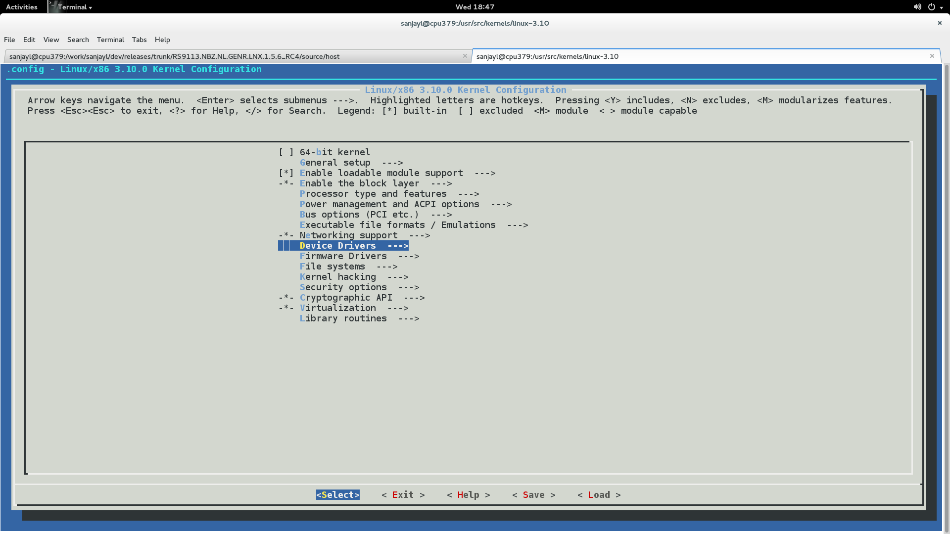
Scroll down to the "Device Drivers --->" option and hit Enter.
In the new menu, scroll down to the "MMC/SD/SDIO card support --->" option and press 'M' to modularize the "MMC/SD/SDIO card support" feature and hit Enter.
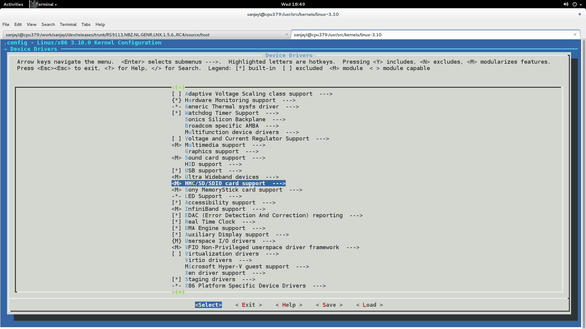
In the new menu, press 'M' to modularize the following options
MMC block device driver
Secure Digital Host Controller Interface support
SDHCI support on PCI bus
Wireless Extension Tools#
Wireless Extension tools like 'iwconfig' and 'iwpriv' are required for configuring the driver. Make sure that the wireless extensions are enabled in the Linux kernel configuration file.
User needs to enable below options in kernel configuration file, re-compile the kernel and cross compile the driver.
   CONFIG_WIRELESS
   CONFIG_WIRELESS_EXT
   CONFIG_WEXT_PRIV
   CONFIG_WEXT_SPY
   CONFIG_WEXT_PROC
   CONFIG_WEXT_CORE
   CONFIG_HOSTAP
Bluetooth Stack Options#
If Bluetooth is required, it must be ensured that the Bluetooth modules are compiled in the kernel. If the Bluetooth modules are not present, follow the steps below to enable Bluetooth support in the kernel.
Navigate to the Linux kernel source folder. This is usually in /usr/src/kernels/linux-<kernel-version>
Execute the 'make menuconfig' command to open the Kernel Configuration menu.
Scroll down to "Networking support --->" and hit Enter.
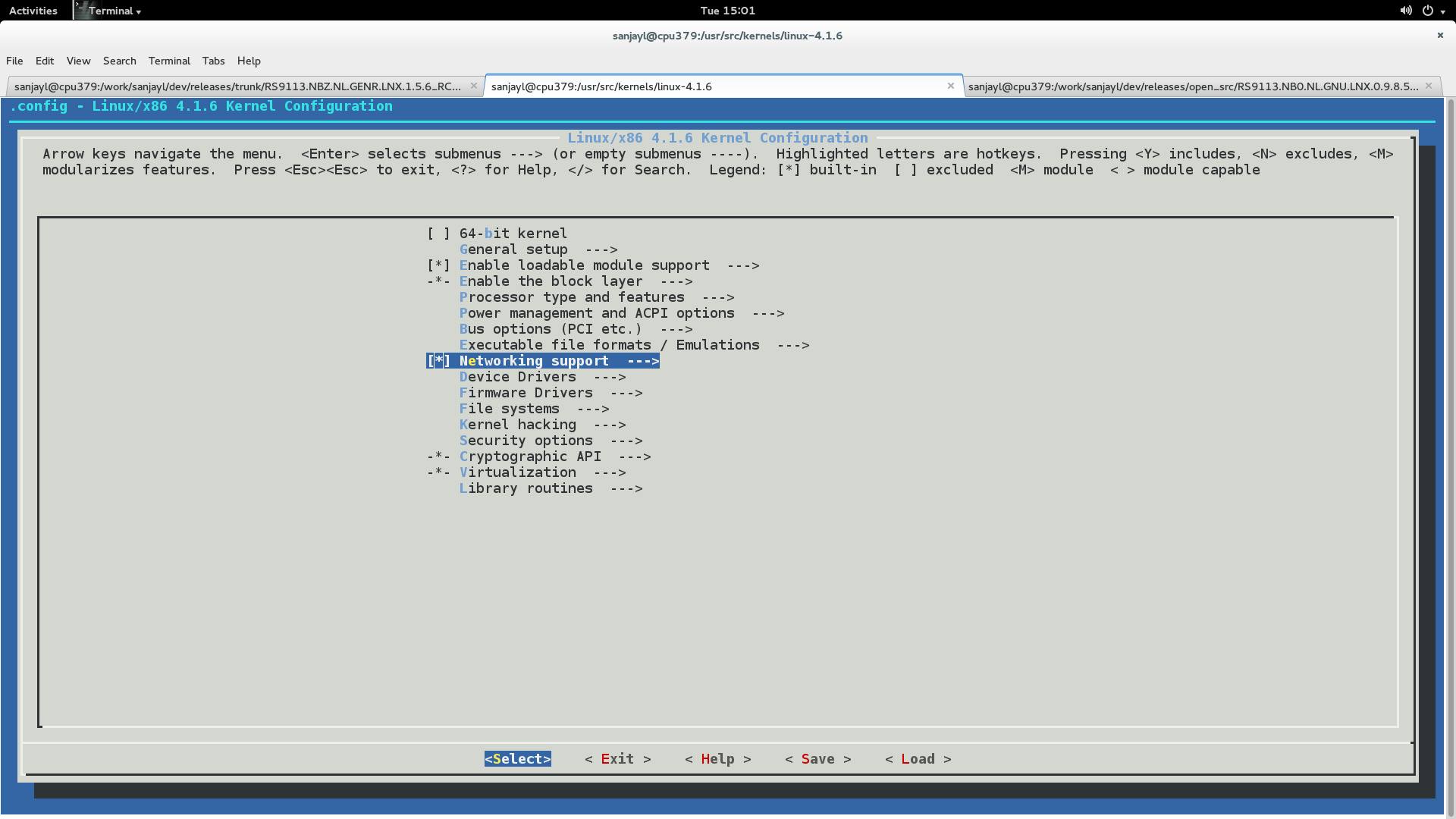
In the new menu, scroll down to the "Bluetooth subsystem support --->" option and press 'M' to modularize the "Bluetooth subsystem support" feature and hit Enter.
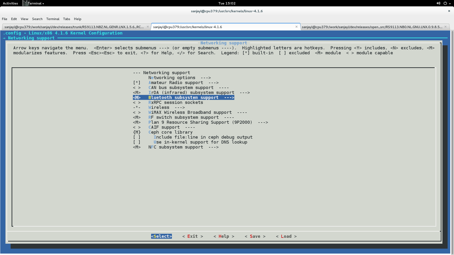
In the new menu, press 'M' to modularize the following options:
RFCOMM Protocol support (enable the "RFCOMM TTY support" feature under this).
BNEP Protocol support (enable the "Multicast filter support" and "Broadcast filter support" features under this).
CMTP Protocol support
HIDP Protocol support
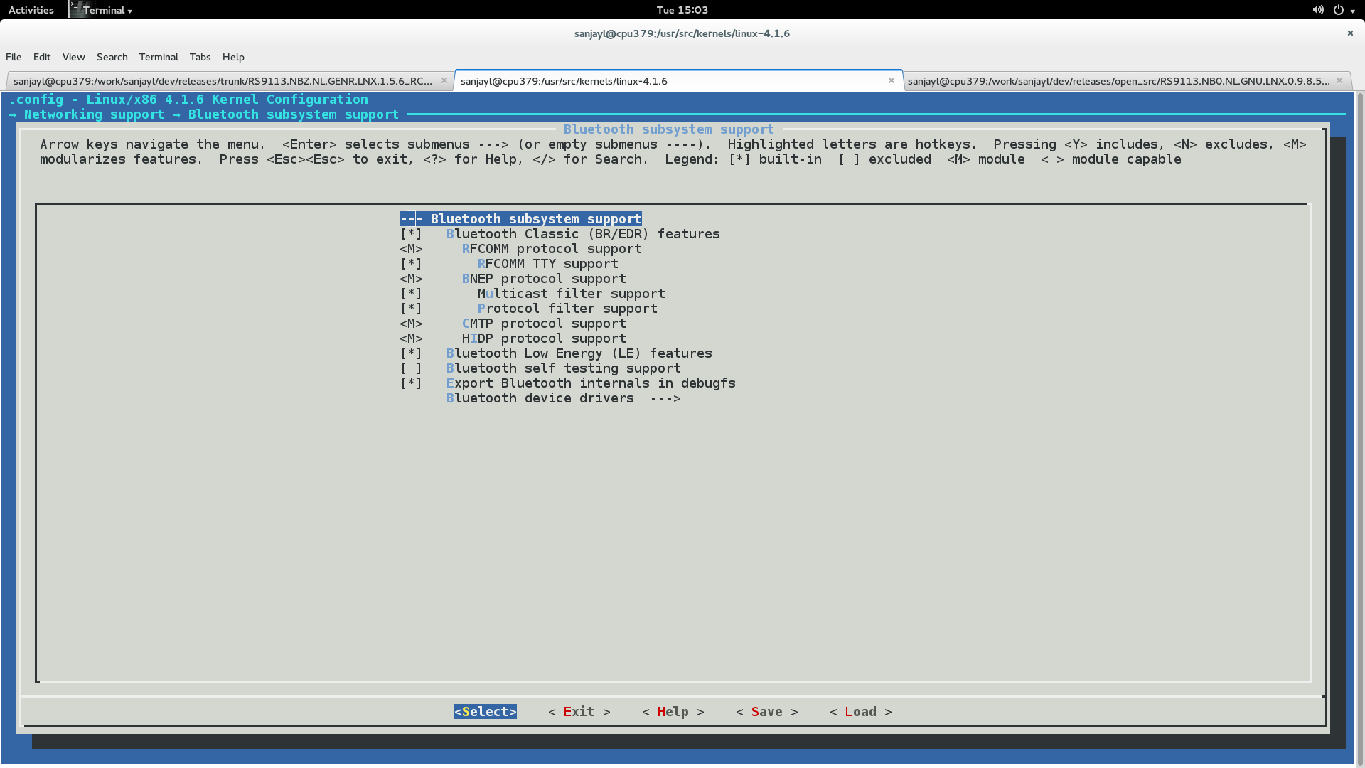
6.Hit the Tab key to select Exit and hit Enter. Repeat this till you are asked whether you want to save the configuration. 7.Select "Yes" and hit Enter. If the above options are already selected, the menuconfig screen will exit immediately.
Kernel Compilation#
The steps used for Kernel Compilation are as follows:
Navigate to the kernel source folder.
Execute the "make" command.
Execute the "make modules" command.
Execute the "make modules_install" command.
Execute the "make install" command. This ensures that the customized kernel is installed, and the boot loader is updated appropriately.
Reboot the system to boot up with the customized kernel.
Appendix F: Configure and Compile Supplicant for Roaming#
Download the supplicant from wpa_supplicant
Extract the supplicant using the following command.
# tar xvf wpa_supplicant-2.6.tar.gz

# cd wpa_supplicant-2.6/wpa_supplicant

# cp defconfig .config
Make sure the following parameters are enabled in the supplicant configuration file (.config)
   ```
   CONFIG_DRIVER_NL80211=y
   CONFIG_BGSCAN_SIMPLE=y
   NL80211_CMD_ROAM=y
   CONFIG_LIBNL20=y
   CONFIG_LIBNL32=y
   CONFIG_WPS2=y
   CONFIG_BGSCAN=y
   ```
Save the configuration file and exit.
Compile the supplicant using "make" command in the following path.
   # cd wpa_supplicant-2.6/wpa_supplicant

   # make clean

   # make
After successful compilation the supplicant executable will be found in the same path. Copy the supplicant executable to the driver release folder.
# cp wpa_supplicant RS911X-nLink-OSD-master/rsi.Roaming#
Configure Connection quality monitoring (cqm) rssi and hysteresis using iw command.
To know more about iw tool, refer to the section Configuration Using Wireless Tools .
   # iw dev <devname> cqm rssi <threshold|off> [<hysteresis>]
   Set connection quality monitor RSSI threshold.


   Example:
   # iw dev wlan0 cqm rssi -45 4
To know more about Background Scan and Set Parameters configuration, refer to the section Background Scan & Roaming .
Appendix G: Installation of Missing Generic Netlink Libraries#
libnl CFlags should be enabled with CONFIG_LIBNL32=y in supplicant and hostpad .config file [The above configuration settings should be set to "y" in case NL80211 is used].
If libnl libraries are not installed in the platform, then follow any of the two methods given below.
Required libnl libraries can be installed through yum/dnf/apt-get/ using below command.
# yum install libnl*Alternately, if you are unable to install libnl libraries using above method, follow below process where we download libnl source package and compile.
Create a directory in the location where Tool chain and BSP are present.
# mkdir buildDownload the libnl 3.2.xx.tar.gz[Referring 3.2.27.tar.gz as an example here ] library and extract it in the build directory.
# cd build<br># tar xvf 3.2.27.tar.gzConfigure the libnl library for target platfrom.
  # CC=/path to the toochain/bin/arm-linux-gnueabihf-gcc
  # ./configure --host=arm-linux-gnueabihf -prefix=<complete path to build directory>
Here headers will be installed in ${prefix}/include/libnl3.
Make and install the libraries in the destination directory or else they will be installed in /usr/local/lib and /usr/local/include/libnl folders of host machine by default.
Follow the example given below:
  # make DESTDIR=$(arm-cortex_a8-linux-gnueabihf-gcc -print -/<path to build directory>/build/)

  # make install
Exporting the path for build directory in the command line or add these flags in the supplicant and hostapd config files under CONFIG_DRIVER_NL80211= y variable.
# export LDFLAGS='-L/<path to build directory>/lib/libnl'OR
Add these flags in the supplicant and hostapd .config files under CONFIG_DRIVER_NL80211= y variable.
 CFLAGS += -I/<path to build directory>/include/libnl3
 Ex: LIBS += -L/<path to build directory>/lib/libnl
 LIBS : Contains a list of additional libraries to pass to the linker command.
Appendix H: Using the Bluetooth Manager#
The steps given below explain about the usage of the Bluetooth Manager in Fedora Core 18 on an x86 platform for pairing Bluetooth devices and transferring files.
Once the Bluetooth modules have been installed as mentioned in section Installation in Bluetooth only modes (BT/BLE) , hit the "Windows" button on the keyboard. You will see Bluetooth symbol at the bottom-right corner of the screen, as shown in the given below figure.
This will open the Bluetooth Manager as shown in the figure below:
Click on Search to start inquiry.
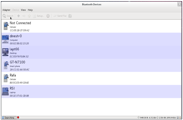
Select a particular device, like your smartphone, right click and select Pair tab to pair with that device.
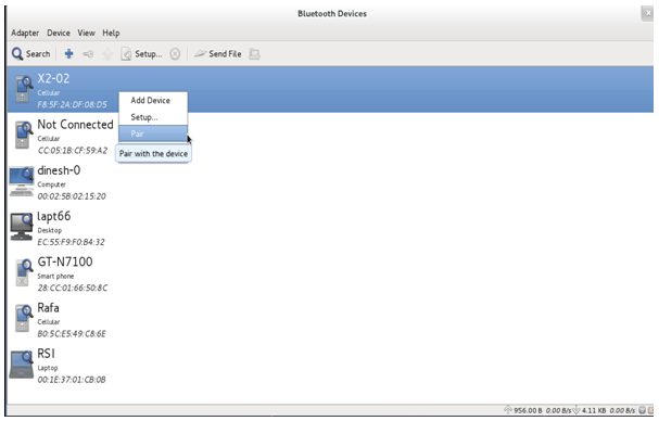
After successfully pairing with the device, right-click on the device and select "Send a file" button to send data to the device. You will be presented with a dialog box to select the file that you wish to send.
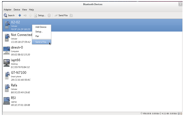
Appendix I: Checking Throughput#
You can measure Wi-Fi performance through UDP/TCP protocols by using the iperf application. If you wish to evaluate the throughputs in Wi-Fi Client mode, you will need to connect a second PC/Laptop to the Access Point. Download and install the iperf application from https://iperf.fr on the second PC/Laptop.
Please note the following points for this evaluation:
To evaluate the module for throughput performance, it's recommended that you connect the second PC/Laptop to the Access Point over Ethernet.
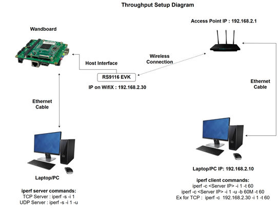
Figure 1: Throughput Measurement Setup Diagram#
It is recommended that you choose a Wi-Fi channel which has less interference, preferably in the 5GHz band if the EVB/module is a Dual band module, to observe optimal throughput of the module.
Wireless throughput vary with the environment of the test setup – distance, obstacles, type of obstacles, etc.
The throughput is also dependent on whether all the Wi-Fi components in the test support only 20MHz bandwidth.
To check Transmit throughput, first run the command below on the 2nd PC/Laptop:
# iperf –s -u -i 1
This command starts an iperf Server which is listening for data. It prints the received throughput at an interval of 1 second. The <-u>option in the above command is for UDP traffic. If it is not mentioned, then the traffic is TCP.
5.Next, run the command below on the PC/Laptop connected to the EVB/module.
# iperf –c <IP address of 2nd PC> -u -i 1 –b 100M –t 120This command starts an iperf Client which starts transmitting data to the Server. The <-u> and <-b 100m> options in the above command are for UDP traffic. If they are not mentioned, then the traffic is TCP.
6.To check Receive throughput, run the Server command first on the PC/Laptop connected to the EVB/module, followed by the client command on the 2nd PC/Laptop.
Example of running throughput:
TCP Server:
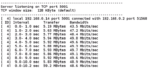
TCP Client:
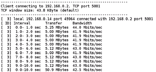
UDP Server:
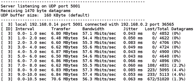
UDP Client:

Appendix J: Steps to Connect EAP-TLS Using wpa_supplicant v 2.6 and Above#
Installing FreeRADIUS Server#
Download FreeRADIUS Server from the link below:
Link: https://freeradius.org/
Note: Try to download the latest release.
After downloading, the file name looks like this
freeradius-server-release_x_x_x.tar.gzUntar the above file
tar -xvf freeradius-server-release_x_x_x.tar.gz
Enter the directory after untar and give following command:
 cd freeradius-server-release_x_x_x/
 ./configure
It will check the necessary prerequisites for the installation. You may get errors like libtalloc not found. Install them with:
dnf install libtalloc*After a successful execution of configure with no errors, give the make command; make install
Connect the radius server installed machine (laptop or PC installed with radius server) to the target AP with a LAN cable.
Get the IP address from the AP by giving:
dhclient <interface name> -r
dhclient <interface name> -v
Open the AP configuration settings in a browser as shown below (expand image for clear view):
Refer to the image above to configure the AP settings.
Note: Block contains 'radius server shared secret ', Enter the shared Secret. Which is used to configure secret in client.conf as explained below.
Enter IP Address which is obtained by dhclient
Radius server Port number is 1812
After a successful configuration, go to directory: cd /usr/local/etc/raddb
Configure two files:
clients.conf [Here, client in the sense, AP (Wi-Fi Router), which require Radius server].
users [Here, users in the sense, clients (mobile phones or station cards), which are going to connect to the above mentioned AP].
Open file /usr/local/etc/raddb/clients.conf, Configure network block as:
client private-network-1 {
  ipaddr = <IP of AP>/24     // example : 192.168.1.1/24

 secret = <shared secret>  //  shared secret configured in AP

 }
Save and close the file.
Example:
Open the /usr/local/etc/raddb/users file and configure identity in the file as given below
<identity> Cleartext-password :=<password for client>
Example : user1 Cleartext-password :="12345678"
Note: Above 'user1' is the identity, 12345678 is the password to be entered in the station settings file or supplicant configuration file.
Save and close the file.
Generate certificates using the process given in the section below and copy certs to /etc folder.
Configure the network block for EAP-TLS in Supplicant configuration file as given below .
Here we need to configure the SSID of AP, identity,password,path for ca_cert, client_cert,private_key, and private_key_passwd.These certificates can be generated using the process given below.
#Enable this block for EAP-TLS
                     network={

                             ssid="<SSID>"

                             key_mgmt=WPA-EAP

                             eap=TLS

                             anonymous_identity="tlsuser"

                             identity="<user>"

                             password="<password>"

                             ca_cert="/etc/certs/ca.pem"

                             client_cert="/etc/certs/client.pem"

                             private_key_passwd="whatever"

                             private_key="/etc/certs/client.key"

                             pairwise=CCMP TKIP

                             group=CCMP TKIP

                             proto=WPA2 WPA

                             priority=20

                      }
Example:
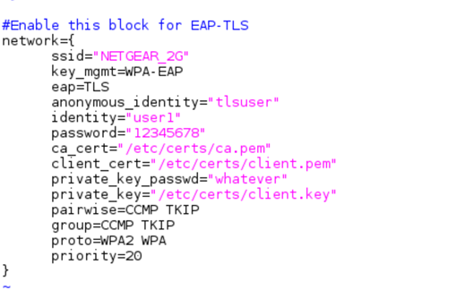
15.Configure the certificate in the server by editing the following entries in the /usr/local/etc/raddb/mods-enabled/eap file.
tls-config tls-common {
private_key_password = whatever
private_key_file = /etc/certs/server.key
certificate_file = /etc/certs/server.pem
ca_file = /etc/certs/ca.pem
Example:
16.Start the Radius server using the command below.
radiusd -X17.Connect the STA by running supplicant. STA should get connected to the AP if all the configurations are proper.
Generate Certificates#
Go to the /usr/local/etc/raddb/certs folder
Remove all the previous certs using the command below:
# rm -f *.pem *.der *.csr *.crt *.key *.p12 serial* index.txt*Generate the CA certificate
# vi ca.cnfThe user can edit "input_password" and "output_password" fields to be the password for the CA certificate.
default_days and default_crt_days are the limits for validity of the certificates. The user can modify as per the requirement.
# make ca.pemThis step creates the CA certificate.
# make ca.derThis step creates the DER format of the self-signed certificate, which can be imported into Windows.
Generate the SERVER CERTIFICATE
The following steps will let you create a server certificate for use with TLS-based EAP methods, such as EAP-TLS, PEAP, and TTLS.
# vi server.cnfUser can edit the "input_password" and "output_password" fields to be the password for the server certificate.
default_days and default_crt_days are the limits for validity of the certificates. The user can modify as per the requirement.
# make server.pemThis step creates the server certificate.
# make server.csrEnsure that the certificate contains the XP extensions needed by Microsoft clients.
Generate the CLIENT CERTIFICATE
Client certificates are used by EAP-TLS, and optionally by EAP TTLS and PEAP. The following steps outline how to create a client certificate that is signed by the server certificate created above. You will have to have the password for the server certificate in the "input_password" and "output_password" fields of the server.cnf file.
# vi client.cnfThe user can edit the "input_password" and "output_password" fields to be the password for the client certificate. You will have to give these passwords to the end user who will be using the certificates.
default_days and default_crt_days are the limits for validity of the certificates. The user can modify as per the requirement.
# make client.pemThis step creates the client certificate.
Note:
i) User can configure input_password and output_password in all three cnf files.
ii) default_days and default_crt_days are the limits for validity of the certificates. The user can modify as per the requirement
After creating all the certs, copy them to the /etc folder:
# cp certs/ /etc -rf
Concurrent Mode#
Concurrent mode is the mechanism in which rsi driver can be operated in AP and Client modes simultaneously. User can create a virtual interface as client mode on one interface and as AP mode on other interface. Below are the Steps to operate the device in concurrent Mode.
Before compiling make sure to Enable CONFIG_STA_PLUS_AP flag in Makefile.
Insert the driver.
# insmod rsi_91x.ko
# insmod rsi_usb.ko  (or) rsi_sdio.ko # According to the interface selected
Add new virtual interface upon the base interface wlan0
# iw dev wlan0 interface add wlan1 type <IFTYPE>
Here IFTYPE : __ap for AP VIF.
              managed for station VIF.
Currently supporting STA + AP or AP +STA combinations only.
NOTE : Make sure 3rd party AP and RSI_AP should be in same channel.
5.To bring up station , configure sta_settings.conf file mentioned in Configure Station using wpa_supplicant section and use below command to run wpa_supplicant.
# wpa_supplicant -i wlan0 -c sta_settings.conf -D nl80211 -dddt > slog.txt&6.To bring up AP, configure ap.conf file mentioned in Wi-Fi Access Point (AP) Mode section. and use below command to run hostapd,
   # hostapd ap_wpa.conf -dddt > hlog.txt&

   **Note: Make sure you add proper interface name in ap_wpa.conf**
Limitations :
More than two virtual interfaces (VIF) is not supported.
Background scan(Bg-scan) and powersave features are not supported for the station mode vap in concurrent mode.Do not enable bgscan_simple in wpa_suppilcant.conf file.
Both interfaces should be in same channel. Channel in hostapd configuration file need to the same channel as the 3rd party AP.
It is recommended to bring up RSI-STA first to avoid performance issues caused by continuous scanning.
Device /chip information#
This IOCTL is to give the details of the Efuse map present in the Efuse/flash in device
Usage of the IOCTL:
After loading the Driver. (insmod rsi_91x.ko and insmod rsi_sdio.ko/rsi_usb.ko).
Go to release folder present in the rsi directory and Give the command below in the release folder.
   cd release/
   ./onebox_util rpine0 print_efuse_map
This should print all the mentioned data below:
Parameter | Description |
|---|---|
EFuse map version | Version no of efuse map |
External-RF chip version | RF chip version no For internal RF, it is same as chip version. For external RF, use same 1.3. |
Module version | Version of the module |
Module part number | Part no of the module |
Mfg s/w version | no of manufacturing software |
Module type | B8 , Q7, Reserved (Q7 + EXT FLASH (QMS)), DB_T, SB, M7DB, M4SB, B6F, B8SDB, W2, W3(WMS) |
Chip version | 0xXY → two nibbles 0x11 →old chips, 0x14 → Rev 1.4, 0x15 → Rev 1.5 |
H/W configuration | (If chip version is not 1.4 ignore this configuration) 0 - 1.4 silicon acting as 1.3, OR 1 - 1.4 silicon only |
Mfg s/w subversion | 3:0 - mfg sw sub-version, 7:4 - Reserved |
Chip identification number | ID number of the chip |
SDB Mode | [ 3: 0 ] : SDB chip mode, 0 - Not a SDB chip, 1 -SDB Master, 2 - SDB Slave1, 3 - SDB Slave2, [ 7:4 ] : Interface card number, 0 : Generic (default) card, 1 : M.2 card |
Usage of start_rs9116.sh script#
To load the driver the user can use the script start_rs9116.sh script. This script file will help to bring up our 9116 module in different modes.
To make use of only BT Classic/BLE then enable the flag in Makefile i.e., "CONFIG_RSI_BT_ALONE=y" and for Wi-Fi+BT/BLE, enable "CONFIG_RSI_COEX_MODE=y". After making this update compile the driver. For compilation steps, check this link Compilation steps section.
The following steps will guide the user how to use the script :
• To use the start_rs9116.sh script, just connect RS9116 module to the host platform and execute the following command.
# ./start_rs9116.sh <mode>Different modes supported :
   • STA
   • AP_STA
   • BT
   • BLE
   • STA_BT
   • AP_BT
   • STA_BLE
   • AP_BLE
   • STA_BT_BLE
   • AP_BT_BLE
Note :
• For IMX6 Wand Board do the following update before running the script :
   a. Change "killall" commands with "pkill" in the script (start_rs9116.sh file).
   b. Disable "rfkill unblock all " command from the script (start_rs9116.sh file) by adding “#” before the line “rfkill unblock all”.
• For station related mode like STA/STA_BT etc. configure the sta_settings.conf file in scripts folder before executing the script. User can follow configure-station-using-wpa_supplicant section to see how to configure sta_settings.conf file.
• If the script throws a print like “Please ensure wpa_supplicant application is present in system” or “Please ensure hostapd application is present in system” or both, then install them and place the binaries in the rsi directory. For the steps to install wpa_supplicant, user can follow this link to install a particular wpa_supplicant version or give the following command to install it.
# apt-get install wpasupplicant• To install hostapd give the following command.
# apt-get install hostapdRS9116 n-Link OSD Software TRM Revision History#
Revision No. | Version No. | Date | Author | Changes | ||
|---|---|---|---|---|---|---|
1 | 0.1 | 15th Feb | Fariya | Initial version | ||
2 | 0.2 | 18th Mar | Prameela Rani | 1. Modified chapter 1 -Modified the content as well as added section 1.1 and 1.2., 2. Modified chapter 2-Package, 3. Modified the whole chapter 3-Compilation & Installation / Un-installation instructions, 4. Modified the content of chapter 4-Device Configuration commands as well as content of section 4.1 and 4.2, 5. Removed chapter 8 | ||
Venkanna | Added section 4.7-Wake on WLAN (WOWLAN) – BT Connectivity under chapter 4 3 | |||||
3 | 0.5 | 3rd Oct, 2017 | Prameela Rani | ZiGB basic details (build, install) added | ||
4 | 0.6 | 5th Oct, 2017 | Prameela Rani | ZiGB usage details added | ||
5 | 0.7 | 26th Oct, 2017 | Prameela Rani | 1. WPS, P2P sections added, 2. Regulatory mapping table added for Caracalla. | ||
6 | 0.8 | 10th May 2018 | Siva Rebbagondla | Removed rsi_zigb.ko insertion and deletetion sections, as zigb modules added to rsi_91x | ||
7 | 1.0 | 25th Oct 2018 | Siva Rebbagondla | Added sdio_clock module_param and RS9116_flash mode details | ||
8 | 1.1 | 13th Mar 2019 | Ganapathi Raju | Added Antenna Diversity in RSI_STA mode. | ||
9 | 1.3 | 24th Dec 2019 | Amol Hanwate | 1. Added Sniffer mode, 2. Added ACS with Hostapd, 3. Added dev_oper_mode 12 details, 4. Removed Concurrent mode, 5. Added Power save section | ||
10 | 1.4 | 3rd April 2020 | Amol Hanwate | 1. Added how to configure 11W, 2. Added BT sniff mode command | ||
11 | 1.5 | 13th Aug 2020 | Ganapathi Raju, Amol Hanwate | 1. Updated power save configuration and added GPIO handshake configurations., 2. Updated BG scan configuration. | ||
12 | 1.6 | Sep 2020 | Pooja Labde, Vandhana Gunti | 1. Added changes as per OSD 2.0 release supported features., 2. Updated document format and structure | ||
13 | 1.7 | Oct 2020 | Pooja Labde, Vandhana Gunti | 1. Added Appendix I: Checking Throughput section., 2. Reviewed and updated compilation and installation sections. | ||
14 | 1.8 | May 2022 | Shivanadam Gude | 1. Added Appendix H: Steps to connect EAP-TLS using wpa_supplicant v2.6 and above section., 2. Added antenna_sel module param in Antenna Selection section., 3. Added Beacon Interval details in Appendix C: Hostapd Usage Guidelines section., 4. Added Selective scan details in Installation in Wi-Fi Only Mode section., 5. Added Update WLAN Region-Based Maximum Powers from Driver section., 6. Added Fast PSP power save profile in Device Sleep Mode section., 7. Added Configuration of AP and RADIUS Server to Use EAP Methods section. | ||
15 | 1.9 | Sep 2022 | Muralidhar Gumparlapati | Ported TRM from pdf to Markdown format | ||
16 | 2.0 | Feb 2023 | Shivanadam Gude, Srinivas Chappidi | 1. Added Concurrent Mode section., 2. Added Usage of start_rs9116.sh file section., 3. Added Device /chip information section., 4. Added pta_config module param in Developer Mode Configuration Parameters section., 5. Added default_deep_sleep_enable module param configuration in Power Save Feature section., 6.Added List of supported HCI commands section., 7. Aligned the document with markdownlint rules |