Z-Wave Association Basics#
NOTE: This section replaces APL12956: Z-Wave Association Basics. Further updates to this application note will be provided here.
Introduction to Device Type and Command Class specification text on Association and Lifeline functionality. This application note also covers association of Multi-Channel devices.
Z-Wave enables a variety of monitoring and control applications. Sensors can send data to a gateway. Wall controllers may report button presses to a scene controller or control actuators directly. A Z-Wave node is conceptually an application resource in a plastic box. Composite devices pack multiple application resources in the same plastic box, sharing the same Z-Wave radio. Application resources can be addressed individually. This is made possible by a range of Command Class and Device Type specifications. For more information, refer to Z-Wave Alliance specifications.
Within a network, a Z-Wave node is identified by its NodeID. The NodeID essentially represents the plastic box and the radio.
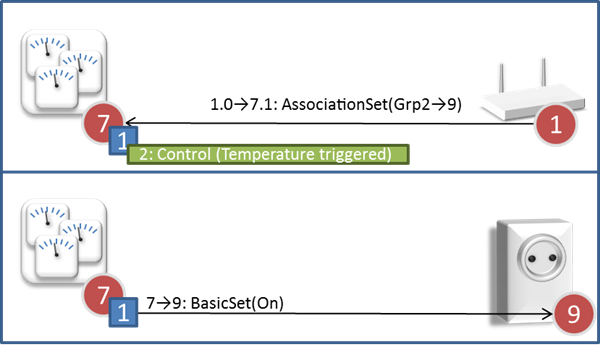
It is possible to configure Sensors and input devices remotely, e.g. via an installer tool, to send data or control commands to other nodes. This process is called association. A given event, e.g. a temperature measurement, is mapped to one or more Association groups.
Association Group Information (AGI) enables Machine-to-Machine (M2M) interfacing as well as human user interpretation of available association groups; thus eliminating the need for paper-based documentation which was needed for the first generation of Z-Wave products.
In this example, a gateway queries the properties of association groups in a sensor device.
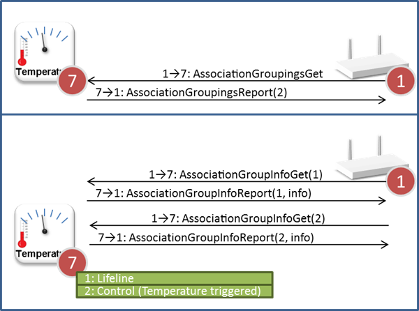
Association group 1 is reserved for the Z-Wave Plus Lifeline service. In the example above, one additional group is implemented; providing temperature triggered actuator control via group 2.
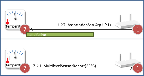
In this example, the Lifeline group enables the temperature sensor to send readings to the gateway.
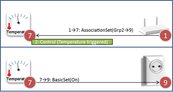
Likewise, association group 2 enables the temperature sensor to locally control a relay module.
An association group may be able to issue more than one type of commands. The Device Type and the Role Type together dictate a minimum feature set to support via the Lifeline group.
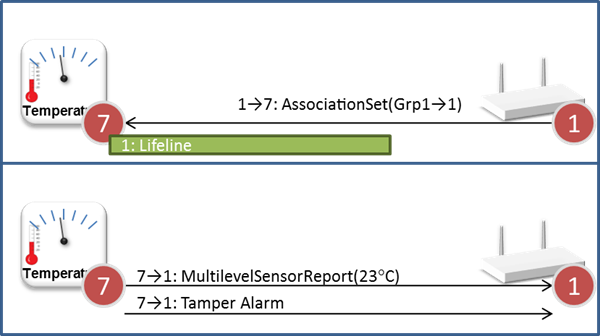
All device centric events are mapped to the Lifeline group. This includes events such as Battery Low, Tamper Alarm and Device Reset Locally. The Lifeline concept allows a gateway to set up just one association from a device to get all it needs. Thus, in the example of a sensor, sensor readings are also mapped to the Lifeline group; while another association group targets local application functionality such as the control of a fan based on temperature thresholds.
Composite products are facilitated by the Multi Channel Command Class. In the example below, two temperature sensors share the same plastic box and radio. The Root Device represents the plastic box and radio. Each Multi Channel End Point implements one application resource, e.g. the indoor temperature sensor.
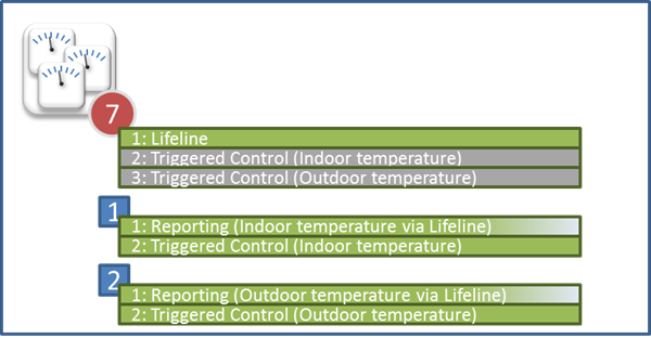
Each End Point advertises via group 1 that this particular End Point can report sensor readings via the Lifeline. By advertising that group 1 supports zero destination nodes, the End Points indicate that there should only be created a Lifeline association from the Root Device Lifeline group.
The Root Device advertises the association groups 2 and 3 on behalf of End Points 1 and 2. These association groups are only advertised for backwards compatibility with non-Multi Channel devices. MultiChannel aware management tools ignore all Root Device application functionality that is also advertised by Multi Channel End Points.
By creating an End Point Association from the Root Device Lifeline group, one enables the reporting of all relevant Lifeline events of the entire device; also events occurring in End Points.
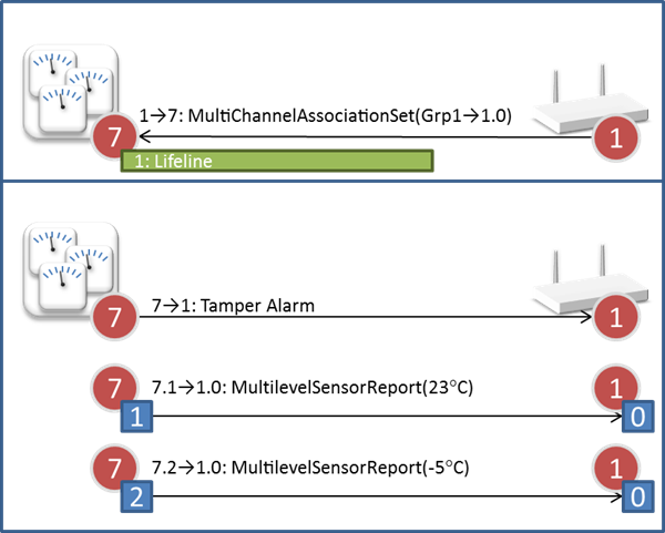
The source End Point identifier allows a receiving gateway to distinguish indoor temperature from outdoor temperature.
Another example is individual meters in an electrical power strip.
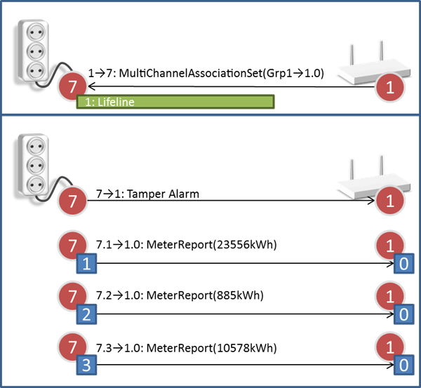
Without the source End Point information, there would be no way to distinguish Meter Reports issued by the three End Points.
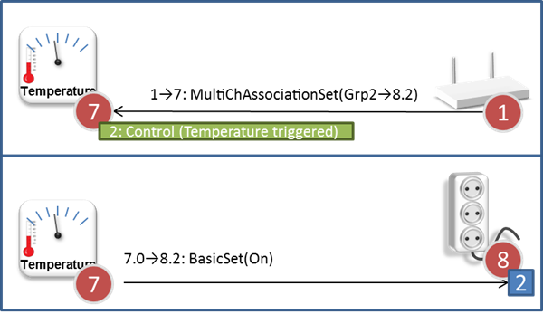
It is also possible to create associations directly from one End Point to another. When creating an End Point association from an End Point, one sends the Multi Channel Association Set command to the actual End Point; not to the Root Device.
The following few examples outline special cases where only one of the nodes actually implement End Points. It is seen that all nodes benefit from supporting Multi Channel communication.
This example shows that even a simple device with only one application resource should be able to send commands to a Multi Channel End Point. If the Root Device communicates to an End Point, it identifies itself by specifying source End Point 0.
A Multi Channel End Point may communicate to a device without Multi Channel support by sending plain commands without Multi Channel encapsulation. The example below shows how a gateway sends a (non-Multi Channel) Association Set command to an End Point to create a NodeID association to a switch module.
This causes the End Point to send its commands to the switch module without Multi Channel encapsulation.
The Multi Channel Association Set command may be used for creating NodeID associations as well as End Point associations.