Z-Wave Control Application Basics#
NOTE: This section replaces APL13084: Z-Wave Control Application Basics. Further updates to this application note will be provided here.
Easy-reading introduction to control application design.
Modern home automation comprises many control applications. This application note explains how to implement robust, interoperable and intuitive lighting applications but the described pitfalls and solutions apply to many other control applications, e.g. window shade control.
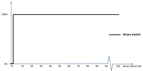
Light may be controlled via relays or dimmers. A relay is said to be a binary switch while a dimmer is categorized as a multilevel switch. Both types may be controlled by OFF and ON commands; OFF is encoded as the value 0, while the value 255 represents the ON command. The binary switch also interprets the values 1..99 as the ON command.
|
| Example 1: Binary switch response to Binary Switch values |
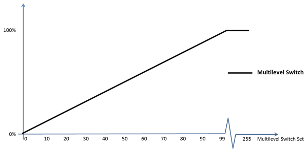
For dimmers, the value 0 signifies the “STANDBY” value; instructing the dimmer to turn off the light while remembering the most recent non-zero level, so that this level can be restored when the “RESTORE” value 255 is received. Dimmers map the values 1..99 to a proportional level in the range 1..100%.
|
| Example 2: Multilevel switch response to Multilevel Switch values |
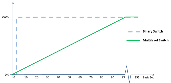
Both relays (binary switch) and dimmers (multilevel switch) support the Basic Command Class. A binary switch interprets the Basic Command Class just as it interprets the Binary Switch Command Class, while a Multilevel Switch interprets the Basic Command Class just as it interprets the Multilevel Switch Command Class. This mapping allows a controlling node to multicast a command to a group of nodes; even if the group comprises a mix of Binary Switch nodes and Multilevel Switch nodes. The value 0 makes all nodes turn off. The value 255 makes all nodes restore the last non-zero level (which is ON for relay nodes). The value 99 makes all nodes go to 100% level (as 99 also maps to ON in relay nodes).
|
| Example 3: Binary and Multilevel Switch response to Basic Set values |
The Basic Set command allows simple control devices like a motion sensor to use Basic Set commands to control resources without knowing if the resource has advanced capabilities such as interactive dimming (explained later in this document).
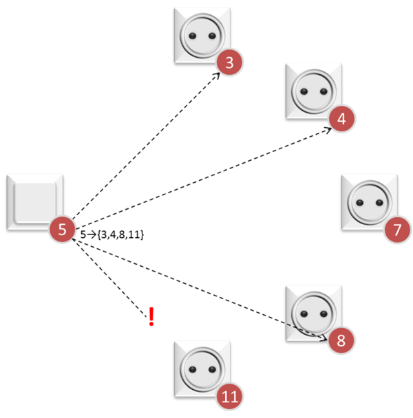
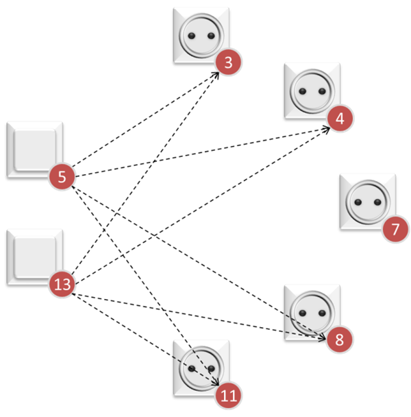
Z-Wave is a wireless technology. Being a shared media, Z-Wave allows commands to be multicasted to a range of nodes in direct range. The wireless properties also introduce a risk that some destination nodes do not receive a command.
|
| Example 4: A multicasted command may not reach all specified destinations |
While a multicasted command may not reach all destinations, the multicasted command is useful for reaching all destination nodes (in direct range) at the same time. This is a good way to avoid the infamous "popcorn effect"; where lamps turn on, one at a time, with visible delay between each event. By sending an acknowledged singlecast command to each destination afterwards a controlling node makes sure that the command reaches all destinations; also the ones out of direct range, and the ones, where the multicast transmission was jammed by RF interference.
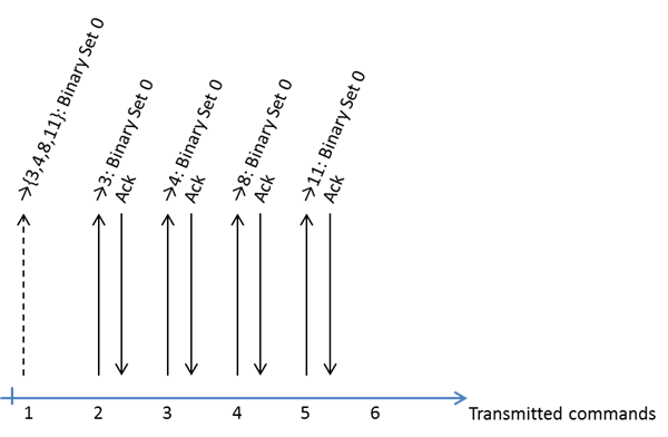
|
| Example 5: Eliminating the “popcorn effect” |
The delivery of singlecasted commands is guaranteed via acknowledgements but higher layers may receive multiple copies of commands due to combined multicasts and singlecasts as well as retransmitted singlecasts.
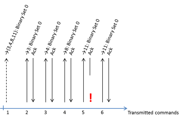
|
| Example 6: Duplication of commands |
As seen in Example 5 and Example 6, it is perfectly normal that a destination node receives two or more commands from the same source. An application may however also receive multiple commands from different sources at virtually the same time by pure coincidence.
|
| Example 7: Synchronization of commands |
All of the above examples outline cases where a destination node receives closely synchronized commands because of intended combination of multicast and singlecast transmissions or because of unintended retransmissions or unintended synchronization of multiple transmitters. In either case, the reception of multiple copies could cause a toggling device to flash repeatedly and even turn off after flashing. Therefore, the Z-Wave eco system does not allow toggling devices.
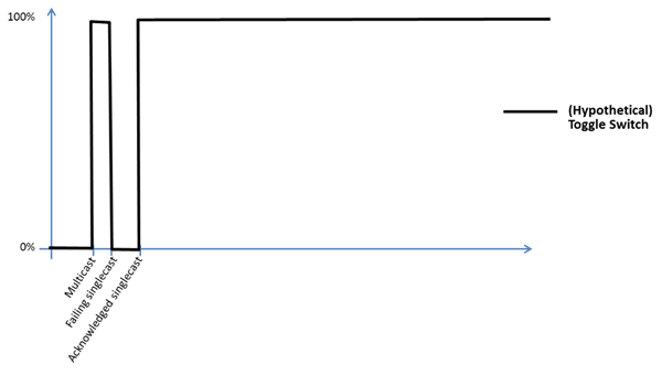
|
| Example 8: Undesirable toggling behavior |
It is tempting to filter out identical commands, but they may not always be identical, e.g. if two sources coincidentally originated commands at (almost) the same time. A filter would not help in that case.
Therefore, a receiving node must tolerate the reception of a control command while the application is already in transition to a new state because of a previously received control command. Such two control commands may be separated by few milliseconds.
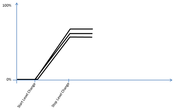
A controlling node may instruct nodes to start dimming up or down in an interactive fashion. Again, the command is first issued using multicast transmission. The transition continues until the controlling node instructs the destination(s) to stop dimming again, or until the destination node reaches the extreme level for the actual transition. To ensure that all destinations reach the same value, the controlling node sends a Stop Level Change command to all destinations as multicast followed by singlecasts.
|
| Example 9: Control response to Start and Stop Level Change commands |
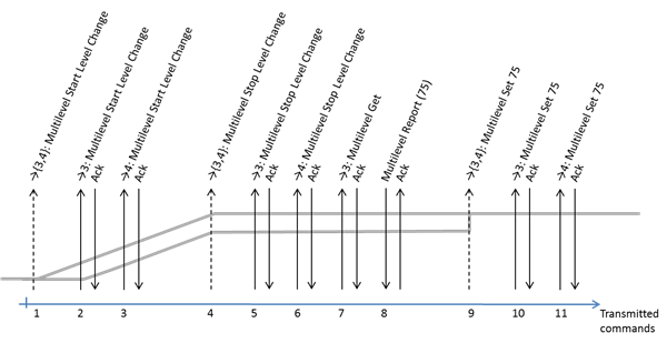
Since the dimming rate may differ slightly and the start of the transition may be delayed by retransmissions, there is a risk that dimmers have reached slightly different levels when instructed to stop dimming. Therefore, the controlling node requests the final level from one dimmer node and instructs all other dimmer nodes in the group to assume that level.
|
| Example 10: Aligning dimmer levels |
Modern lighting devices may provide color control. The Color Switch Command Class is used to adjust the color tone of the device via RGB codes as well as cold white and warm white components.
The Multilevel Switch or Binary Switch Command Classes are used to control the intensity of color capable devices. Thus, a classic lighting remote control can control the full intensity range of a color capable device. It is not allowed for a controlling node to adjust the intensity of a color device via the RGB levels as this would prevent classic light control devices from controlling the full intensity range of color capable devices via the Basic and Multilevel Switch command classes.
Just as the Multilevel Switch Start Level Change command allows for interactive intensity control, the Color Switch Start Level Change command allows a simple remote control to change color interactively. After stopping the Color Switch Level Change transition, the controlling node must request the color tone from one color node and assign the same color tone to all other color nodes in the group.
A controlling node should take into account that color capable nodes may support varying combinations of RGB, warm white and cold white. It may therefore be necessary to perform an initial color calibration at installation time.
Since color tone and intensity control is completely separated, a controlling node may skip updating the intensity in all nodes in the group if only the color is adjusted. Likewise, a color capable device may be capable of just turning a color tone on or off. In that case the light intensity may be controlled via the Binary Switch command class rather than the Multilevel Switch command class.
While this application note presents examples from a light control application, the signalling sequences used to synchronize events and aligning levels may also be used to control other device types, e.g. window drape controllers.