Z-Wave Multi-Channel Basics#
NOTE: This section replaces APL12955: Z-Wave Multi-Channel Basics. Further updates to this application note will be provided here.
Easy-reading introduction to Device Type and Command Class specification text on Multi-Channel functionality. This application note introduces basic Multi-Channel functionality. Association and Lifeline is introduced in Association Basics.
Z-Wave enables a variety of monitoring and control applications. Sensors can send data to a gateway. Wall controllers may report button presses to a scene controller or control actuators directly. A Z-Wave node is conceptually an application resource in a plastic box communicating via a Z-Wave radio. Composite devices pack multiple application resources in the same plastic box, thus sharing the same Z-Wave radio. Application resources can always be addressed individually.
This is made possible by a range of Command Class and Device Type specifications.
Within a network, a Z-Wave node is identified by its NodeID. The NodeID essentially represents the plastic box and the radio. Multi-resource devices are organized as Multi-Channel Endpoints. Each application resource is identified by its own unique End Point. The plastic box itself is referred to as the Root Device.
Multi-Channel Encapsulation allows a sending node to specify a source End Point and a destination End Point. Further, the destination End Point may be structured as a multicast mask, targeting up to 7 End Points by one command. If a device implements no actuator functionality, it may not always be necessary to structure resources as Multi-Channel End Points.
A multi-sensor with two distinct sensor types is one example. Another example is a remote control that sends Central Scene Notifications to a central gateway via the Lifeline association group. The remote control may advertise additional association groups, each representing a push button for direct actuator control. Without an icon type for each End Point, a graphical management tool has to render such input elements graphically based on the AGI Profile, e.g. Control:Key01.
Wall controllers, that only transmit commands, represent a gray zone. A remote control manufacturer may consider the wall controller to be just a remote control in a different form factor. This manufacturer sees no value in End Points.
A manufacturer of wall switches with built-in dimmers may consider the wall controller to be a downscaled wall switch where the load controlling hardware is omitted. This manufacturer may prefer to apply the same End Point structure to similar products for development and support reasons.
Multi-Channel Encapsulation is used for transmission from one End Point to another, from an End Point to a Root Device as well as from a Root Device to an End Point.
In case of similar sensor types in the same device, End Points are needed to distinguish the sensor reports from the individual sensor resources. AGI allows the controller to determine the nature of the sensor, e.g. “Indoor temperature”.

|
| Example 1: Two identical sensor resources distinguished via the Source End Point |
The wall controller below implements one End Point for each button.
|
| Example 2: End Point 1 of one node controlling End Point 2 of another node |
The next wall controller implements no End Points. All association groups are provided by the Root Device.
|
| Example 3: Root Device of one node controlling End Point 2 of another node |
Note that while the wall controller in Example 3 implements no End Points itself, it still has to support Multi-Channel communication in order to control actuator End Points in other devices.
Multi-Channel Encapsulation is not used between Root Devices.
|
| Example 4: Root Devices communicating without Multi-Channel encapsulation |
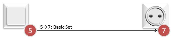
Historically, there could be only one application resource in one plastic box. In such a simple device, functionality relating to the plastic box, e.g. battery level, and application functionality, e.g. light control, are all accessed via the NodeID. Thus, the application functionality of a simple device resides in the Root Device, while a Multi-Channel device has no application functionality in the Root Device.
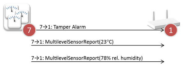
Backwards compatibility is maintained in Multi-Channel devices by the Root Device advertising application functionality, even though the functionality is actually provided by one or more End Points. End Point 1 implements the primary functionality of the device, but the product designer is free to mirror functionality of more End Points to the Root Device. As an example, the Root Device of a composite sensor may mirror the management function of two sensor End Points, causing both End Points to send sensor reports.
|
| Example 5: Root Device mirrors two End Points in composite sensor |
Mirroring multiple End Point sensor resources in the Root Device requires that the resources issue different commands. A receiving device has no way to distinguish identical reports.
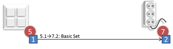
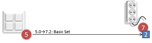
In the same way, the Root Device of a power strip forwards commands to all three End Points of the device.
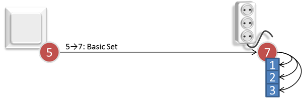
|
| Example 6: Root Device mirrors three End Points in power strip |
One cannot be sure that a command to the Root Device mirrors all End Points. The Multi-Channel multicast feature may be used to send a Set command to the first 7 End Points. Alternatively, one may communicate to each individual End Point. This works for Set as well as Get commands.
Management tools may have a need to present expanded views of Multi-Channel devices, e.g. in the floor plan view of a smart home deployment. Such tools hide Root Device application functionality to compensate for the backwards compatibility mirroring of End Point functionality to the Root Device. This way, the power strip can be presented the way it really works.