Z-Wave Networking Basics#
NOTE: This section replaces APL13031: Z-Wave Networking Basics. Further updates to this application note will be provided here.
Easy-reading introduction to Z-Wave networking functionality. This application note introduces network management, routing, and service discovery.
Z-Wave enables a variety of monitoring and control applications. The basis for the applications is the networking services provided by the Z-Wave Protocol.
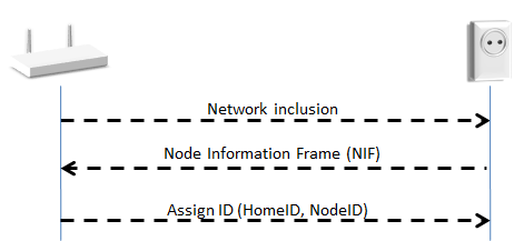
The Z-Wave Protocol can add and remove nodes in a network. This is known as inclusion and exclusion.
|
| Example 1: Gateway adding a lamp to the network |
A Z-Wave node is identified by its NodeID. All nodes in the network share the same HomeID. The NodeID and HomeID are assigned during inclusion. Inclusion is managed by a node known as the Primary Controller.
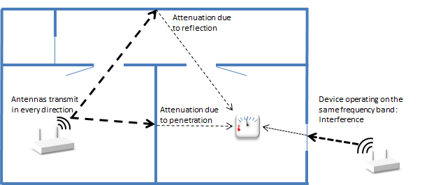
Wireless links may be affected by varying levels of attenuation, reflection, jamming, humidity and other physical phenomena.
|
| Example 2: Wireless link quality issues |
These phenomena may vary due to a change in the weather, a person walking through the building or a refrigerator door being opened.
Due to metal in the building construction materials, wireless link properties may also be affected if a node is moved just by a small distance.
Each frame carries a checksum. A Receiving node can verify the frame integrity thanks to this checksum. Invalid frames are discarded.
A Receiving node returns an Ack message in order to confirm that the frame has been received. If no Ack is received by the Sending node, it must assume that the transmission failed. The Sending node will then retransmit the same message until it gets feedback from the Receiving node. After three unsuccessful transmissions, the Sending node will consider the link to be down.
Ack messages are sent to confirm the frame integrity and do not imply that the Receiving node has understood or executed the command.
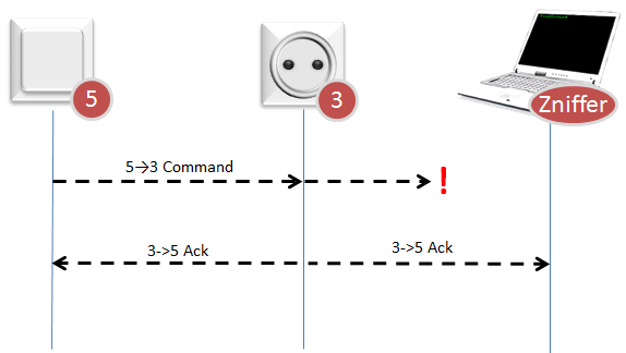
Local differences in wireless link quality may cause a Z-Wave network analyzer (known as a Zniffer) not to see the same transmissions as nodes participating in a transmission.
|
| Example 3: Network analysis issues |
The Zniffer may receive a corrupted transmission whereas the Receiving node sees no error. The Zniffer will then see an unexpected Ack from the Receiving node.
In the same way, the Ack message from the Receiving node may not be correctly received by the Sending Node but received without problem by the Zniffer. The Zniffer will then observe the same command sent again even though the message appears to be received at the first attempt.
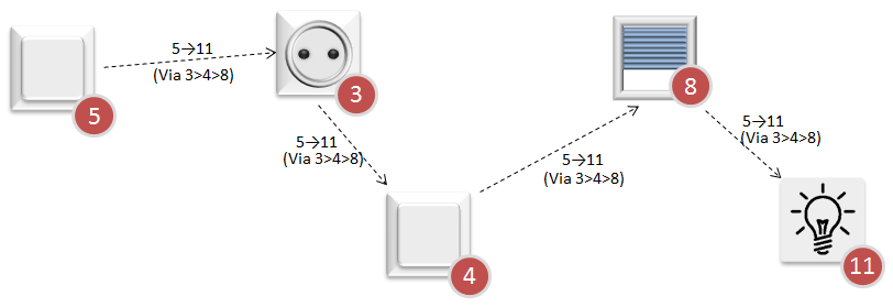
The Z-Wave Protocol handles transmissions to destinations all over the network. If necessary, other nodes are used as repeaters. This is called routing.
During bootstrapping, the Primary Controller asks the new node to discover its neighbors. Thanks to the neighbor nodes information, the Primary Controller builds a network map and knows the different possible routes to reach a node.
When using repeaters, the Sending node includes the route information in the frame. Each repeater parses the routing information and forwards the frame accordingly.
|
| Example 4: Routing via repeaters |
Routing may also be used during inclusion if a node is not within direct range of the Primary Controller.
When a link has failed, the Sending node may try another route, using the network map information.
When all known routes have failed, the Sending node may use an Explorer Frame as a last resort. The Explorer Frame will be relayed by other nodes, recording the route it takes, until it eventually reaches the target node.
The target node will use the reverse route to answer back to the controller upon Explorer Frame reception.
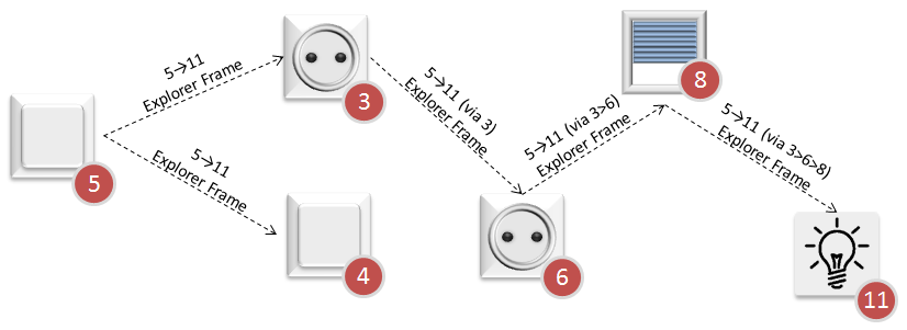
|
| Example 5: Explorer Frame |
Different nodes may have different capabilities. When the Primary Controller includes or excludes node in a network, the node sends its Node Information Frame (NIF). The NIF is a special frame that describes the network and application capabilities of a node.
One node may have several sensors or actuators that the Primary Controller can interact with. Even in this case, the node has only one NodeID and each sensor/actuator is represented as an End Point.
The Primary Controller can use the Association Group Information (AGI) to get a node to report certain events. AGI advertises the device trigger points that can cause unsolicited frames to be transmitted. Typical triggers include button press, sensor reading or alarm event.
AGI profiles also indicate the type of sensors. By learning about the Association Groups, the Primary Controller can determine what type of sensor the node comprises.