Application Development#
Prototyping APIs#
To automate device creation for prototyping, scripts are available that create the necessary objects in the cloud and the manufacturing page. These scripts are provided in the Silicon Labs extension for Amazon Sidewalk Github repository. To set up a prototype device and register it to the network the following steps are necessary:
Deploy your application in AWS.
Compile and flash an application for your embedded device.
Create a device profile in AWS.
Create a wireless device in AWS.
Generate a manufacturing page.
Flash the manufacturing page to your embedded device.
You can deploy your AWS application automatically using dedicated tools like Amazon CloudFormation. You can compile and flash your application using Simplicity Studio 5. To create the device profile, wireless device, and manufacturing page you can use Silicon Labs' prototyping script.
Remember to install the requirements listed in the requirements.txt file under amazon_dependencies with pip3 install -r requirements.txt.
The script configuration is handled by a JSON file like the following:
{
    "awsAccount": {
        "awsRegion": "us-east-1",
        "awsProfile": "default"
    },
    "commanderPath": "C:\\SiliconLabs\\SimplicityStudio\\v5_4\\developer\\adapter_packs\\commander\\commander.exe",
    "generationRequests": [
        {
            "deviceProfileId": null,
            "deviceName": null,
            "destinationName": "CFSDestination",
            "targetPart": null,
            "quantity": 1
        }
    ]
}
An example configuration file is provided at the root of the repository.
The first block awsAccount is used to configure the connection to AWS cloud:
awsRegion: The AWS region you would like to add your devices to (Note that only theus-east-1region is supported at the moment).awsProfile: Used to choose the AWS CLI profile linking to the correct credentials. If you do not use profiles, you can leave the default.
The second block defines the toolchain used to create the manufacturing page:
commanderPath: Should link to the the Simplicity Commander executable file.
The third block generationRequests controls the target device details:
deviceProfileId: If this is your first time running the script, it should be empty. If not, it contains your Device Profile ID (this field is filled automatically).deviceName: This is optional, you can choose to give a custom name to your device.destinationName: Should be the name of the destination used by your AWS cloud application.targetPart: The OPN of the target part. If empty, manufacturing pages for all supported radio boards will be generated.quantity: The quantity of devices you want to create (default value is 1).
On the first run, the script creates a prototyping device profile and fills the deviceProfileId with the resulting device ID. All subsequent wireless devices will be created using this device profile. Note that during prototyping, a device profile can be linked to a maximum of 1000 wireless devices.
To start the script, execute the following:
python3 generate_prototype.py --input <.> --output <output_folder> --config example_config.jsonnumber_of_instances is the number of devices you want to create (default value is 1).
The script creates a directory structure as follows in the chosen output folder under mfg_output:
DeviceProfile_7c51bc6b-0556-2083-6f0d-aeb750c94508
├── DeviceProfile.json
└── WirelessDevice_db57b1c9-22ad-c052-07ae-1e1cae9bb384
    ├── SiLabs_MFG.nvm3
    ├── Silabs_xG21.s37
    ├── Silabs_xG23.s37
    ├── Silabs_xG24.s37
    ├── Silabs_xG28.s37
    └── WirelessDevice.json
The first directory is named with the device id of your device profile and contains DeviceProfile.json, which contains your device profile information. Then a directory is created for every wireless device you created. One wireless device contains manufacturing pages for all supported platforms and a WirelessDevice.json file containing your device information (including private keys).
To use the script with command-line arguments instead of a configuration file, simply drop the --config parameter.
usage: generate_prototype.py [-h] [-i INSTANCES] -in INPUT -out OUTPUT [-p AWS_PROFILE] [-n NAME] [-d DST_NAME] [-t TARGET] [-c COMMANDER] [-cfg CONFIG]

optional arguments:
  -h, --help            show this help message and exit
  -i INSTANCES, --instances INSTANCES
                        Number of instances to generate (default: 1)
  -in INPUT, --input INPUT
                        Path of the input directory
  -out OUTPUT, --output OUTPUT
                        Path of the output directory
  -p AWS_PROFILE, --aws-profile AWS_PROFILE
                        Name of your AWS profile from .aws/credentials (default: default)
  -n NAME, --name NAME  Specified name for the newly created device (default: sidewalk_[user]_device)
  -d DST_NAME, --dst-name DST_NAME
                        Destination name used for uplink traffic routing (default: CFSDestination)
  -t TARGET, --target TARGET
                        Target part number for which the MFG page generation has to be done (default: all)
  -c COMMANDER, --commander COMMANDER
                        Path to commander executable, not needed if already in system PATH
  -cfg CONFIG, --config CONFIG
                        Configuration file, if provided other arguments are ignored
Non-Volatile Memory Use#
Amazon Sidewalk example applications use non-volatile memory to store the application code, registration information, and manufacturing data. This section describes how this memory is used for each type of data stored.
⚠ WARNING ⚠: Starting Sidewalk extension 2.x.x, a change was made to the NVM3 usage in Sidewalk. This change is not backward compatible, you should be careful to use the manufacturing page generation that corresponds to the Sidewalk version that you are using.
In addition to the application code, one other NVM3 instance is used in an Amazon Sidewalk project: Default. The default instance is also used by the Simplicity SDK Suite for BLE stack status and cryptographic storage. This is where the wrapped private keys are stored when using Secure Vault. For more information, see section 2.1 of AN1135: Using Third Generation Non-Volatile Memory (NVM3) Data Storage.
The default instance consists of the following logical partitions and subpartitions:
Partition | Subpartition | Key Range | Comments |
|---|---|---|---|
Simplicity SDK | BLE stack metadata | 0x40000 - 0x4FFFF | Used internally by Simplicity SDK for BLE stack |
PSA crypto metadata | 0x83100 - 0x870FF | Used internally by Simplicity SDK for PSA crypto | |
PSA crypto wrapped keys | 0x83100 - 0x870FF | When using Secure Vault, Sidewalk ED25519 and P256R1 device private keys are wrapped in this subpartition | |
Sidewalk | Application specific | 0xA0000 - 0xA1FFF | Sidewalk applications can store data on this partition |
KV-storage | 0xA2000 - 0xA8FFF | Reserved for sidewalk stack usage | |
Manufacturing data | 0xA9000 - 0xAFFFF | Reserved for sidewalk stack usage |
The manufacturing (MFG) partition is used to store the manufacturing page generated for every device. The manufacturing page contains various information such as device public keys, signatures, and Sidewalk Manufacturing Serial Number (SMSN). This instance is read-only from application code.
The Key-value (KV) storage partition contains information about the Amazon Sidewalk stack. The way the key-value pairs are stored on NVM3 is a bit different from the way the manufacturing information is stored. Objects are stored under groups, so there is actually one NVM3 object (so-called group) to store different information. The size of this instance depends on the needs of the stack (depending on the link layer). The values stored in the instance are not part of the public Amazon Sidewalk APIs. This instance is accessible in read-write from application code.
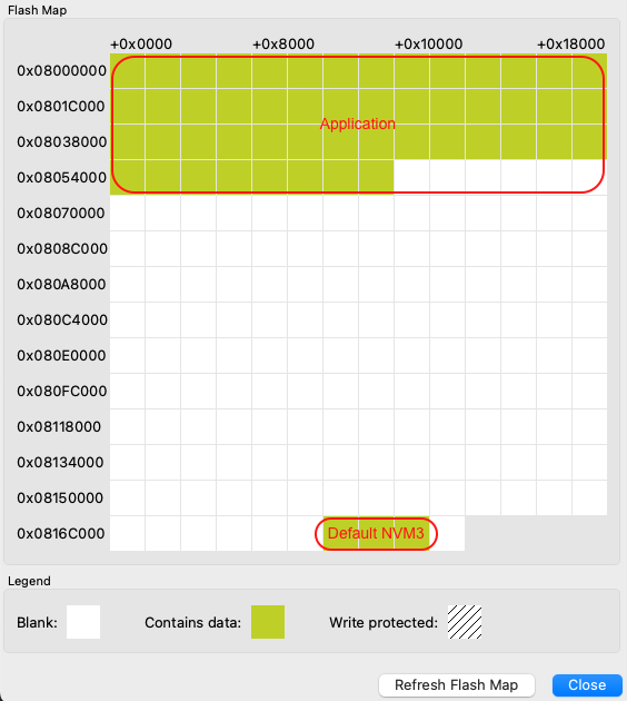
You can see an example of the memory layout in the following picture:


For more information on Silicon Labs NVM driver, see the dedicated documentation NVM3 - NVM Data Manager. For background on NVM3, see the Platform Resources section.
Memory Map for EFR32xG21 Series#
Region | Base Address | End Address | Size | Description |
|---|---|---|---|---|
Application | 0x00000000 | - | - | Application code - size depends on application |
Default NVM3 Instance | 0x000EC000 | 0x000F2000 | 0x6000 | Used for BLE stack. Wrapped keys are stored here when using Secure Vault. |
Those addresses are given as an example for an EFR32xG21 with a flash size of 1024 kB. Base addresses can change to adapt to smaller flash sizes. You can use Simplicity Commander to display the memory layout of your application:
With your kit selected, go to Device Info panel.
Select Flash Map in Main Flash panel.
Memory Map for EFR32xG24 Series#
Region | Base Address | End Address | Size | Description |
|---|---|---|---|---|
Application | 0x08000000 | - | - | Application code - size depends on application |
Default NVM3 Instance | 0x0816C000 | 0x08172000 | 0x6000 | Used for BLE stack. Wrapped keys are stored here when using Secure Vault. |
Those addresses are given as an example for an EFR32xG24 with a flash size of 1536 kB. The base addresses can change to adapt to smaller flash sizes. You can use Simplicity Commander to display the memory layout of your application:
With your kit selected, go to Device Info panel.
Select Flash Map in Main Flash panel.
Credentials Backup/Restore Feature#
The out-of-the-box (OOB) application provided with the Pro Kit has a feature that allows users to erase the flash memory without losing the device private keys and other device-specific information. The feature relies on the user data partition that is not affected by mass-erase but it can still be erased. This feature can be used alongside Secure Vault seamlessly.
The manufacturing page needs to persist in order for the application to work in the Amazon Sidewalk network. This data can be divided in two groups, one for device-specific information and the other for information common to all devices created under the same device profile. As the capacity of the user data partition is quite limited, the common information is stored in the application code and only the device-specific information is backed up on the user data partition.
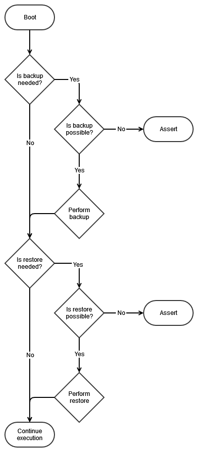
The following flow diagram shows the backup/restore feature workflow.


The Backup feature is used to copy device-specific information from the manufacturing page onto the user data partition. There is no need to copy common information as it is hard-coded in the application. Backup takes place when the application cannot detect any backed up data on the user data partition. This implies that, if the user data partition is erased but not the application, then the application will perform a backup process after each boot.
The Restore feature is used to copy device-specific information from the user data partition and common information from the OOB application code onto the manufacturing page. Restore takes place when the application cannot detect any valid manufacturing page. This implies that, if the device is mass-erased, then the application will perform a restore process after each boot and restore the whole manufacturing page.
Move to Custom Hardware#
Configure Transceiver GPIOs#
Some Silicon Labs devices, like those in the EFR32xG28 family, support the FSK sub-GHz Sidewalk protocol natively (see the Hardware section in Getting Started: Prerequisites for more info). Other devices require an external transceiver for Sidewalk FSK support, which also provides support for the other sub-GHz Sidewalk protocol: CSS. For development purposes, this transceiver is conveniently available on the Semtech SX1262MB2CAS LoRa shield. The Semtech shield can be connected to a main board using either an adapter board (recommended) or 10 female-to-female jumper wires (if adapter board is not available). Using this third-party sub-GHz radio module enables sub-GHz Sidewalk communication (CSS and FSK) from EFR32xG21 and EFR32xG24 radio boards. Note that the Semtech shield is not necessary with the KG100S, as a Semtech transceiver is already integrated in that module.
Ⓘ INFO Ⓘ: For superior signal integrity, ease of use, and a more robust development platform, Silicon Labs recommends the Sidewalk Adaptation Board (BRD8042A, included in the Silicon Labs Pro Kit for Amazon Sidewalk) instead of jumpered wire connections.
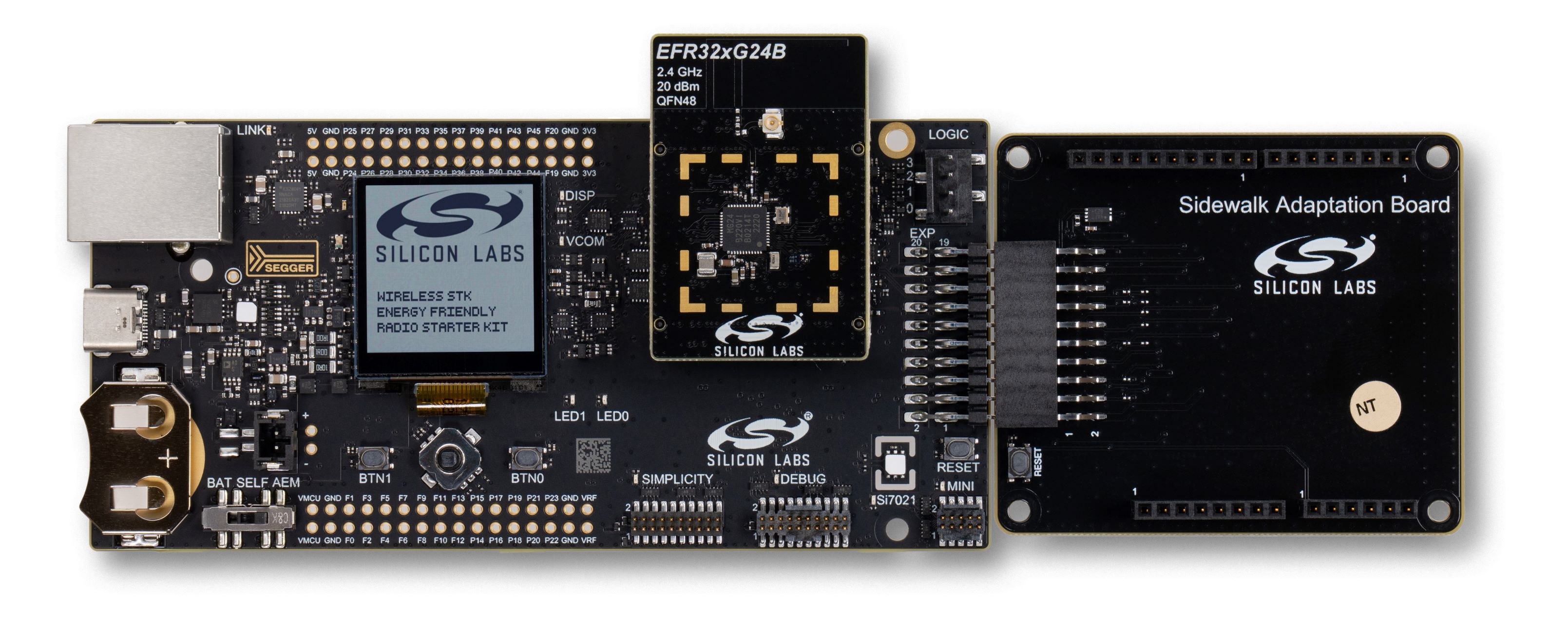
When using the Sidewalk Adaptation Board, connect it to the main board Expansion Header as shown below, and mount the Semtech shield to the female pin headers on the Adaptation Board.


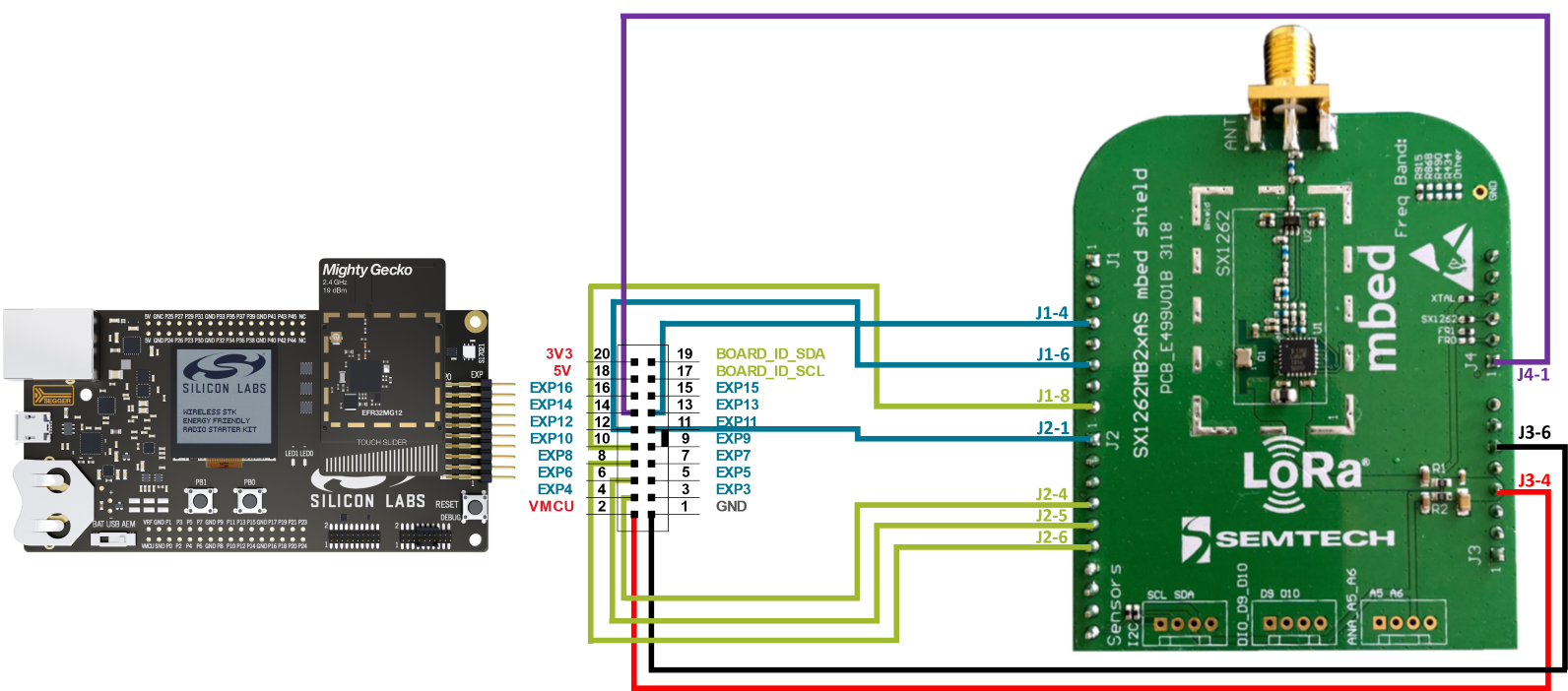
When using jumper wires, connect the Semtech shield to the main board Expansion Header with the following scheme:
EFR32 Mainboard Exp. Pin | Semtech Shield Pin | Function |
|---|---|---|
EXP_HEADER 1 | J3-6 | GND |
EXP_HEADER 4 | J2-4 | SPI MOSI |
EXP_HEADER 6 | J2-5 | SPI MISO |
EXP_HEADER 8 | J2-6 | SPI SCK |
EXP_HEADER 10 | J1-8 | SPI NSS |
EXP_HEADER 11 | J2-1 | ANT_SW |
EXP_HEADER 12 | J1-6 | DIO1 |
EXP_HEADER 13 | J1-4 | BUSY |
EXP_HEADER 14 | J4-1 | SX NRESET |
EXP_HEADER 2 | J3-4 | VMCU |
The information in the table is also represented in the following image.


If you wish to customize the wiring between your sub-GHz chip and the EFR32, you can implement such changes in your application with the Pin Tool (in Simplicity Studio). When using the KG100S module, you also need to edit the GPIO mappings in file config/app_gpio_config.h in the sub-GHz example applications, the file autogen/app_gpio_config.c will be generated accordingly.
⚠ WARNING ⚠: In KG100S applications Silicon Labs recommends not using the SPI peripheral, because the multi-chip module (MCM) design already leverages it for communication between the EFR32 and the Semtech radio transceiver. Sharing the SPI bus with additional devices can negatively impact time-critical radio control signals and lead to message failure in sub-GHz protocols.
