BLE Auto PA mode#
Introduction#
The EFR32 families of chips each come equipped with two or three Power Amplifiers (PAs):
EFR32xG1x
A high-power 2.4 GHz PA (for power 20 dBm and lower)
A low-power 2.4 GHz PA (for power 0 dBm and lower)
EFR32xG21
A high-power 2.4 GHz PA (for power 20 dBm and lower)
A medium-power 2.4 GHz PA (for power 10 dBm and lower)
A low-power 2.4 GHz PA (for power 0 dBm and lower)
EFR32xG22
A high-power 2.4 GHz PA (for power 6 dBm and lower)
A low-power 2.4 GHz PA (for power 0 dBm and lower)
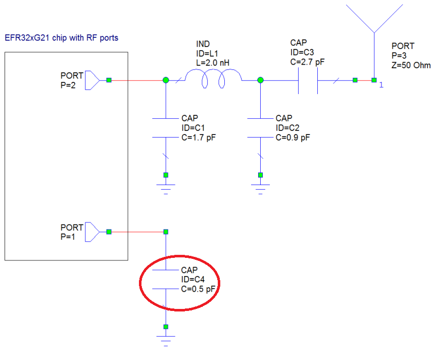
Each PA maps to different TX output power curves. While using high-power or medium-power PA, TX power under 0 dBm may get a very inaccuracy output. While using low-power PA, TX power cannot set above 0 dBm. In most use cases, the antenna matching network works well in one range only (either above 0 dBm or below 0 dBm), and hence this is not a big problem. In some use cases, however, high accuracy output is needed both above and below 0 dBm. In this case, an automatic switching between the PAs is needed. This article discusses how to achieve this.
Enabling Auto PA Mode#
By default, the used PA can be configured under the configuration of RAIL Utility, PA software components, as shown here:
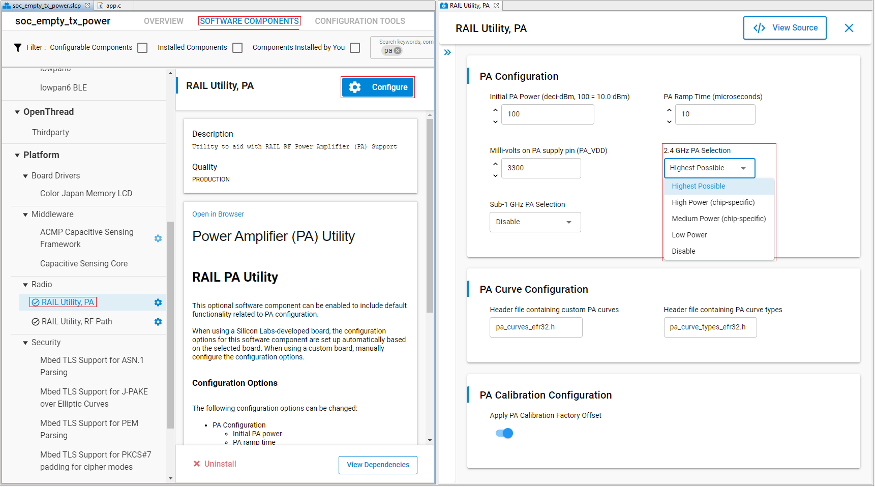

However, this lets you select a fixed PA only, and does not enable auto PA mode. Currently, auto PA mode can be enabled in source code by directly editing the config\sl_bluetooth_config.h in your project. Find the following configuration and change the .pa.pa_mode to SL_BT_BLUETOOTH_PA_AUTOMODE:
#define SL_BT_CONFIG_DEFAULT                                                   \
  {                                                                            \
    .config_flags = SL_BT_CONFIG_FLAGS,                                        \
    .bluetooth.max_connections = SL_BT_CONFIG_MAX_CONNECTIONS_SUM,             \
    .bluetooth.max_advertisers = SL_BT_CONFIG_MAX_ADVERTISERS,                 \
    .bluetooth.max_periodic_sync = SL_BT_CONFIG_MAX_PERIODIC_ADVERTISING_SYNC, \
    .bluetooth.max_buffer_memory = SL_BT_CONFIG_BUFFER_SIZE,                   \
    .scheduler_callback = SL_BT_CONFIG_LL_CALLBACK,                            \
    .stack_schedule_callback = SL_BT_CONFIG_STACK_CALLBACK,                    \
    .gattdb = &gattdb,                                                         \
    .max_timers = SL_BT_CONFIG_MAX_SOFTWARE_TIMERS,                            \
    .rf.tx_gain = SL_BT_CONFIG_RF_PATH_GAIN_TX,                                \
    .rf.rx_gain = SL_BT_CONFIG_RF_PATH_GAIN_RX,                                \
    .rf.tx_min_power = SL_BT_CONFIG_MIN_TX_POWER,                              \
    .rf.tx_max_power = SL_BT_CONFIG_MAX_TX_POWER,                              \
    .pa.config_enable = BT_PA_CONFIG_STATE,                                    \
    .pa.input = BT_PA_POWER_SUPPLY,                                            \
    .pa.pa_mode = SL_BT_BLUETOOTH_PA_AUTOMODE,                                             \
  }
Note, that this, in itself, is not enough to switch between PAs automatically. You also have to define the rules of switching, i.e., between what circumstances you want to switch PAs. To define this, RAIL provides the RAILCb_PaAutoModeDecision() callback function, which can be overwritten in your application. For example, if you want to use high power PA above 10dBm, mid power PA between 0 and 10dBm and low power PA below 0dBm, apply the following function:
#include "rail.h"

RAIL_Status_t RAILCb_PaAutoModeDecision(RAIL_Handle_t railHandle,
                                        RAIL_TxPower_t *power,
                                        RAIL_TxPowerMode_t *mode,
                                        const RAIL_ChannelConfigEntry_t *chCfgEntry)
{
  if(*power < 0) {
    // Use the LP PA when is below 0dBm
    *mode = RAIL_TX_POWER_MODE_2P4GIG_LP;
  } else if((*power >= 0) && (*power <= 100)) {
    // Use the MP PA when TX power is from 0dBm to 10dBm
    *mode = RAIL_TX_POWER_MODE_2P4GIG_MP;
  } else {
    // Use the HP PA when TX power is over 10dBm
    *mode = RAIL_TX_POWER_MODE_2P4GIG_HP;
  }
  return RAIL_STATUS_NO_ERROR;
}Verification#
To verify whether the Auto PA mode is working properly, first check the set_max value returned by the sl_bt_system_set_tx_power() API command. This value tells you the actual (maximum) power level set by the stack, which may differ from the originally requested value because of the limitation of different PAs. The table below shows the requested and the actual set values for different TX power levels and different PA settings, tested on a EFR32xG21 chip. The following code example may help to test the same on your board: Testing TX Power Levels.
Note, that the unit used here is 0.1 dBm.
Requested | Set with HP PA | Set with MP PA | Set with LP PA | Set with Auto PA |
|---|---|---|---|---|
-260 | -260 | -260 | -260 | -260 |
-250 | -260 | -260 | -246 | -246 |
-240 | -260 | -260 | -246 | -246 |
-230 | -260 | -260 | -231 | -231 |
-220 | -260 | -260 | -215 | -215 |
-210 | -260 | -260 | -215 | -215 |
-200 | -260 | -260 | -200 | -200 |
-190 | -260 | -260 | -184 | -184 |
-180 | -260 | -260 | -184 | -184 |
-170 | -155 | -260 | -169 | -169 |
-160 | -155 | -144 | -154 | -154 |
-150 | -155 | -144 | -154 | -154 |
-140 | -155 | -144 | -138 | -138 |
-130 | -113 | -144 | -123 | -123 |
-120 | -113 | -96 | -123 | -123 |
-110 | -113 | -96 | -108 | -108 |
-100 | -113 | -96 | -92 | -92 |
-90 | -72 | -96 | -92 | -92 |
-80 | -72 | -96 | -77 | -77 |
-70 | -63 | -74 | -68 | -68 |
-60 | -63 | -57 | -60 | -60 |
-50 | -46 | -57 | -48 | -48 |
-40 | -46 | -40 | -39 | -39 |
-30 | -24 | -29 | -29 | -29 |
-20 | -24 | -19 | -19 | -19 |
-10 | -13 | -9 | -9 | -9 |
0 | -3 | 1 | -6 | 1 |
10 | 9 | 11 | -6 | 11 |
20 | 21 | 17 | -6 | 17 |
30 | 27 | 29 | -6 | 29 |
40 | 39 | 41 | -6 | 41 |
50 | 51 | 51 | -6 | 51 |
60 | 59 | 61 | -6 | 61 |
70 | 70 | 70 | -6 | 70 |
80 | 74 | 80 | -6 | 80 |
90 | 89 | 90 | -6 | 90 |
100 | 101 | 100 | -6 | 100 |
110 | 111 | 100 | -6 | 111 |
120 | 118 | 100 | -6 | 118 |
130 | 130 | 100 | -6 | 130 |
140 | 140 | 100 | -6 | 140 |
150 | 150 | 100 | -6 | 150 |
160 | 160 | 100 | -6 | 160 |
170 | 170 | 100 | -6 | 170 |
180 | 180 | 100 | -6 | 180 |
190 | 190 | 100 | -6 | 190 |
200 | 200 | 100 | -6 | 200 |
For a full verification, also check the TX power levels with a spectrum analyzer. In this case, the following API is recommended: sl_bt_test_dtm_tx_v4(). This API lets you transmit packets continuously on a single channel with a given TX power. While unmodulated carrier is the ideal signal to measure, the API does not allow to set unmodulated carrier with TX Power > 12.7 dBm. As a result, the packet type sl_bt_test_pkt_11111111 should be used.
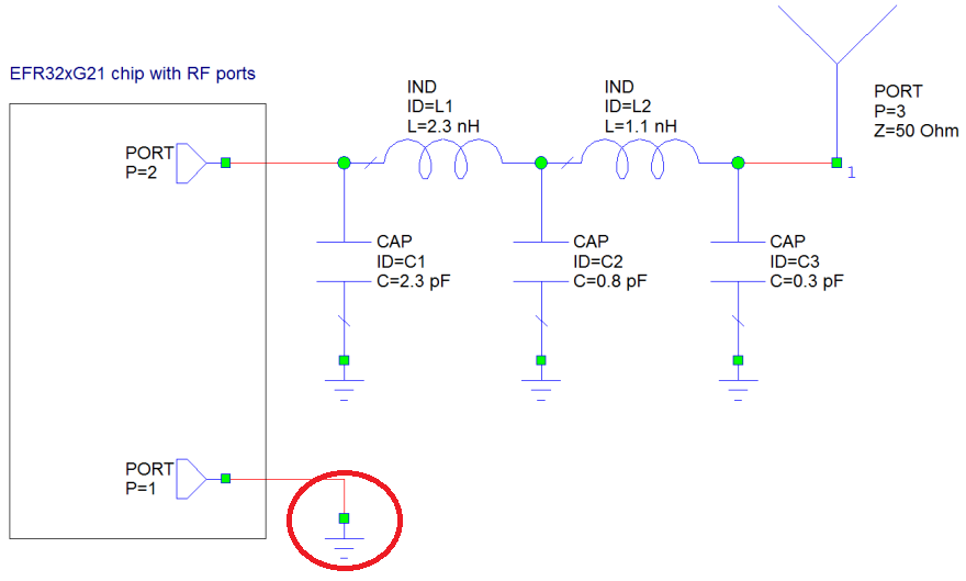
Note that when you measure the output TX power, the matching network also plays a big role. For guidance about the matching network design, see AN930.2.
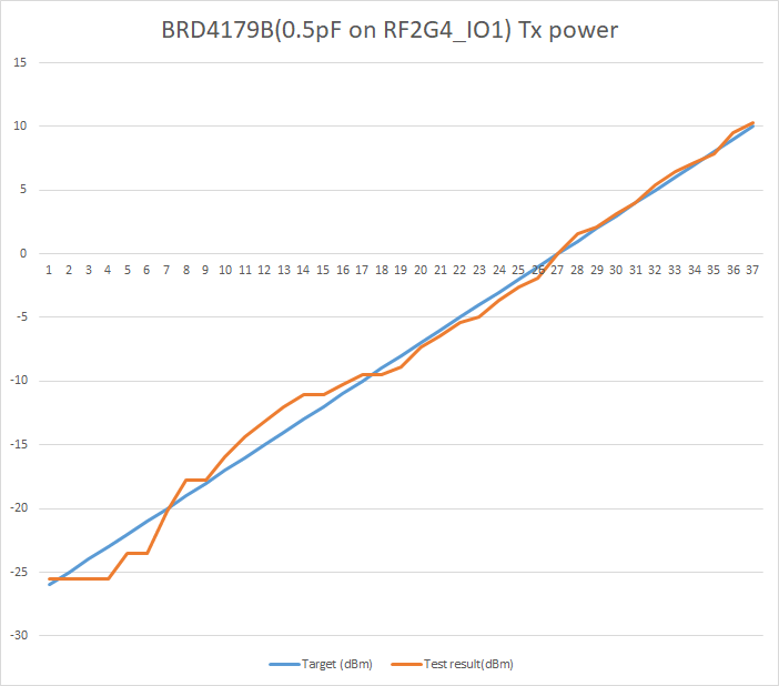
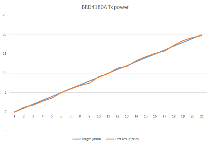
Below you can see test results for two boards. Tester: Agilent E4405B spectrum analyzer Config: Frequency = 2440 MHz, Span = 2 MHz, Amplitude ref = 20 dBm, Amplitude offset = 1.6 dB
BRD4180A with original matching network, tested between 0 dBm and 20 dBm.


BRD4179B with modified matching network to support low power PA (see AN930.2), tested between -26 dBm and 10 dBm:
