Testing and Results#
Latency#
The latency was tested both in the open-air and RF-shielded environment.
Bluetooth Mesh Unicast Latency#
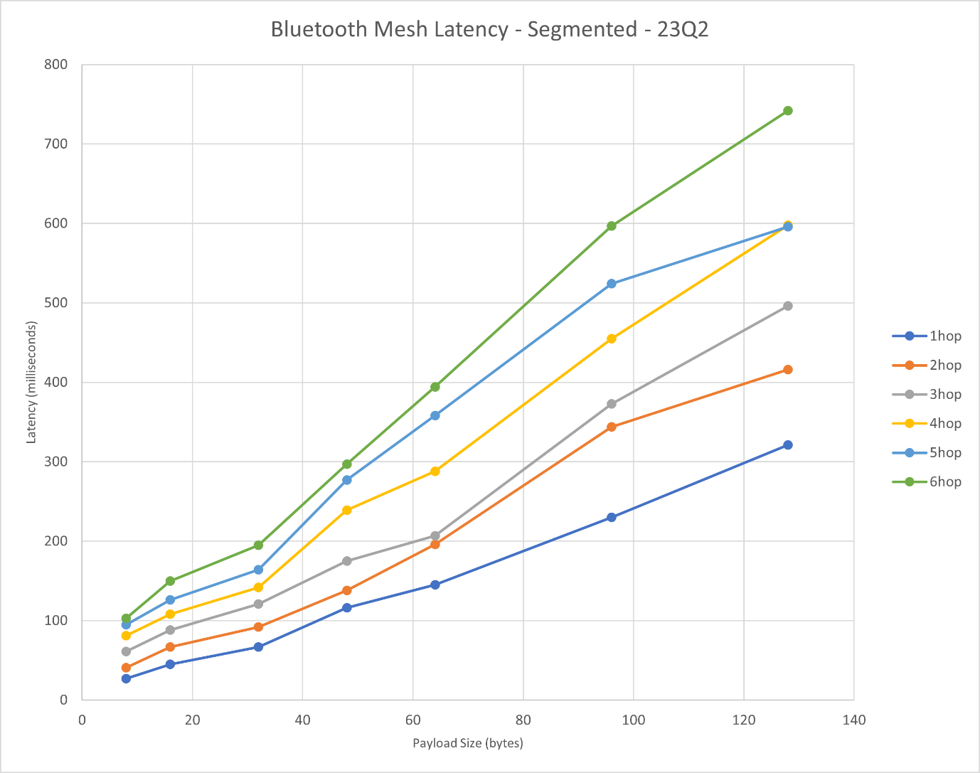
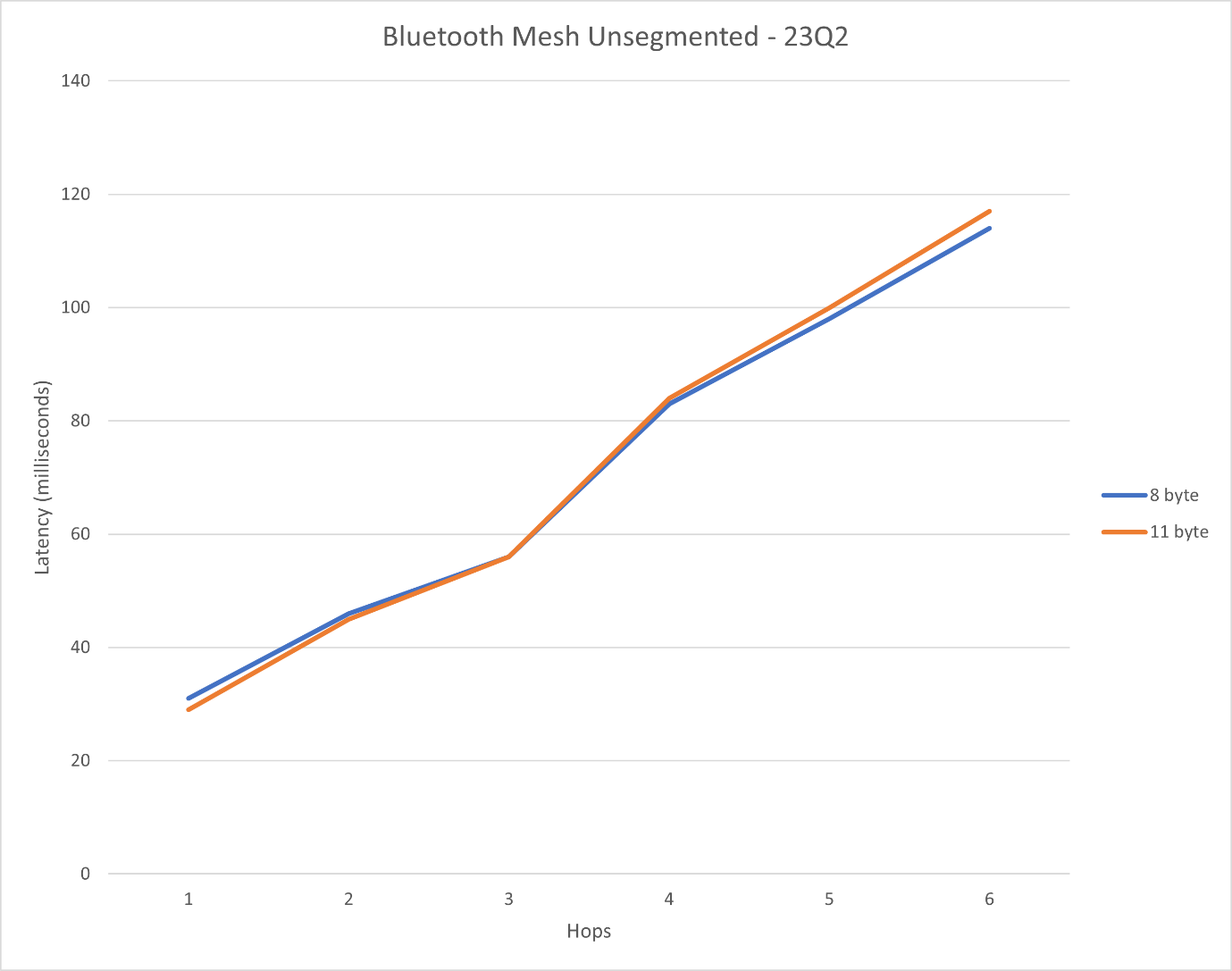
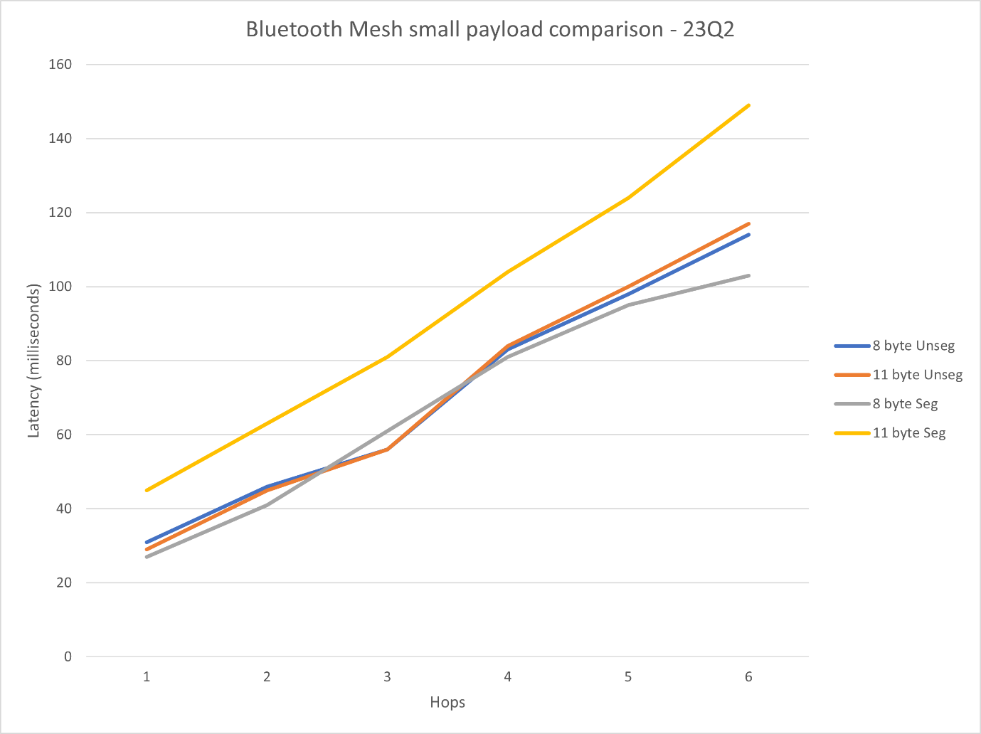
Silicon Labs tested sending unicast one-to-one payload messages at the defined rate and measuring the packet round trip time, by having the client model acknowledge the packets sent by the server mode in one of two ways:
Lower transport layer acknowledgements of segmented PDUs
Client model layer acknowledgements of unsegmented PDUs
During the tests, only one relay was configured for each hop.
The following parameters were used for each test:
Parameter | Description | Used Values |
|---|---|---|
Size of network | Number of nodes used for the test | 2-8 |
Run size | Number of payload sends to attempt | 1,000 |
PDU size | Size of the PDU in bytes | 8, 11, 16, 32, 48, 64, 96, 128 |
Net TX | Network transmission repeat count | 3 |
Relay TX | Relay level repetition count | 3 |
Rate | Rate at which the messages are dispatched from the server in ms | 1,500 |
Number of hops | The number of daisy-chained relay nodes in the network | 1-7 |
Segmentation | 8 and 11 bytes PDUs can be send out without segmentation, but segmentation forcing can be set up | 8, 11 bytes: with and without segmentation 16, 32, 48, 64, 96, 128: with segmentation |
Bluetooth Mesh Multicast Latency#
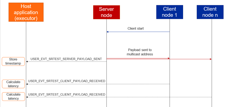
For this test, there was one server node and multiple client nodes subscribed to a network address. The server sent the packets to this address, and the time between sending and receiving on a given client was measured for each client separately.
The server node was set to be a device on box #6 in the lower right corner of the office, in order to ensure that at least one naturally occurring hop was in the network.
The test steps:
Configure the server and the clients.
One client triggers the payload sending on the server with the desired configuration using a Test Config message.
Server sends payloads and generate BGAPI events, which are recorded.
Clients receive payloads and generate BGAPI events, which are recorded.
Process the recorded event to calculate latency.
The parameters used for the test:
Parameter | Description | Used Values |
|---|---|---|
Size of network | Number of nodes used for the test | 10, 50, 100, 256 |
Run size | Number of payload sends to attempt | 1,000 |
PDU size | Size of the PDU in bytes | 8, 16, 32 |
Net TX | Network transmission repeat count | 3 |
Relay TX | Relay level repetition count | 3 |
Rate | Rate at which the messages are dispatched from the server in ms | 3,000 |
Relay frequency | The frequency at which the nodes are set to behave as a relay (5 meaning that every 3rd node in the network is set to be a relay) | 1, 6 |
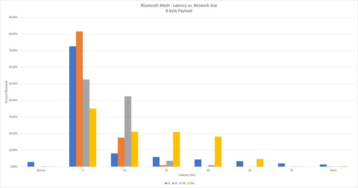
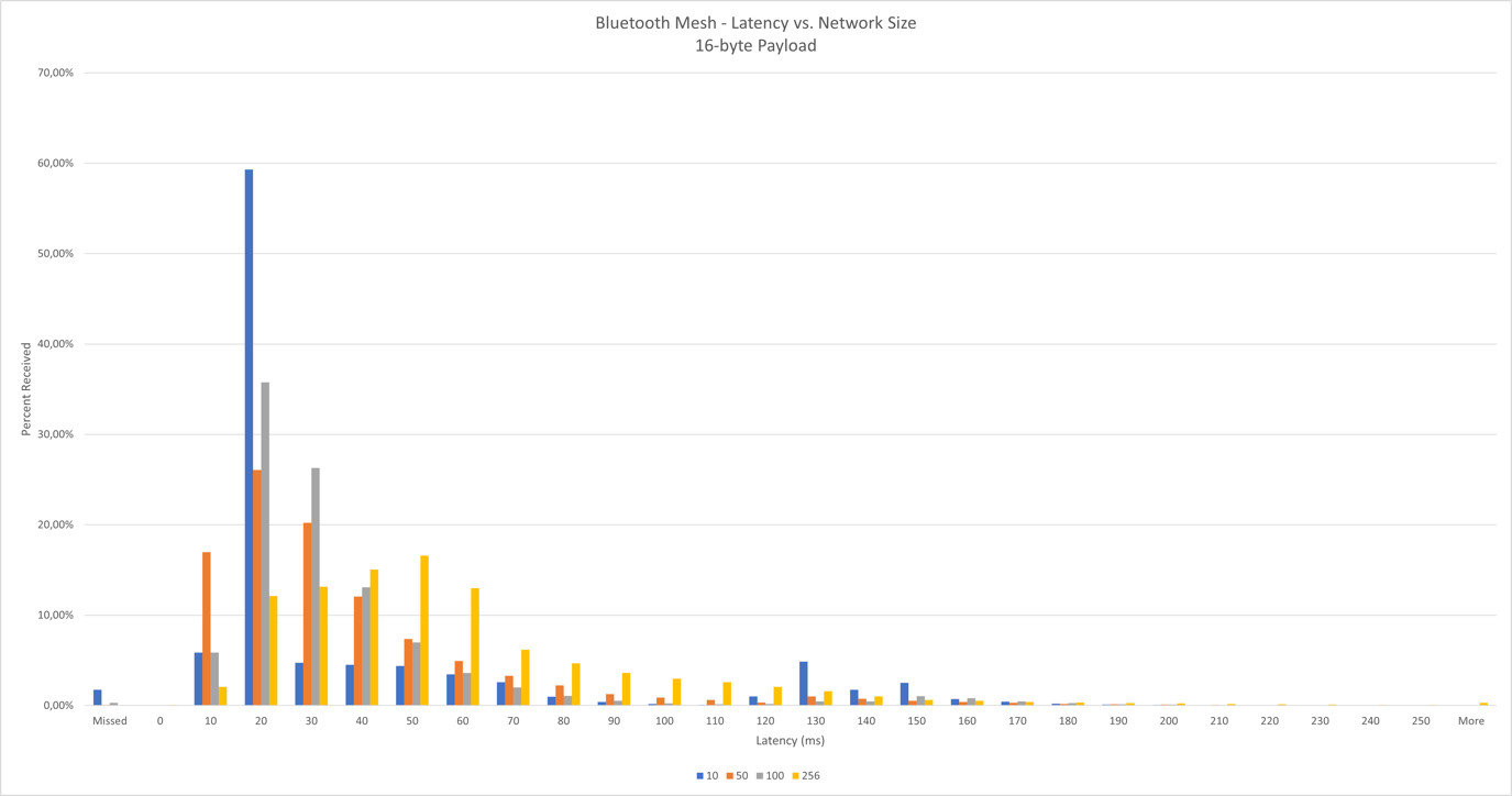
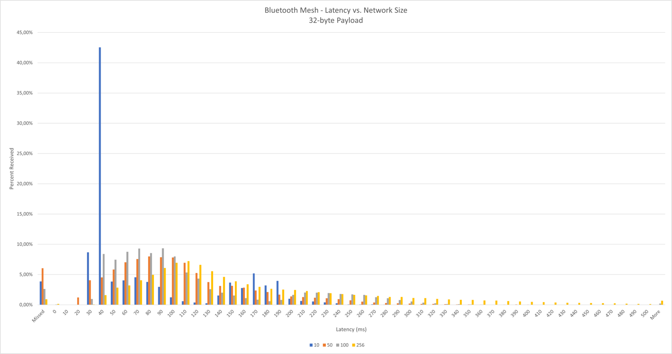
Results based on node network size
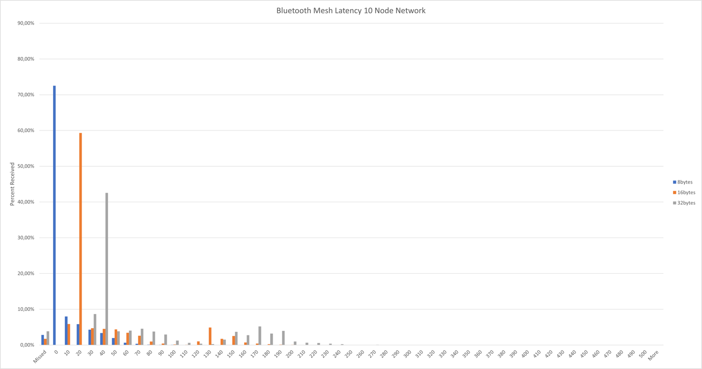
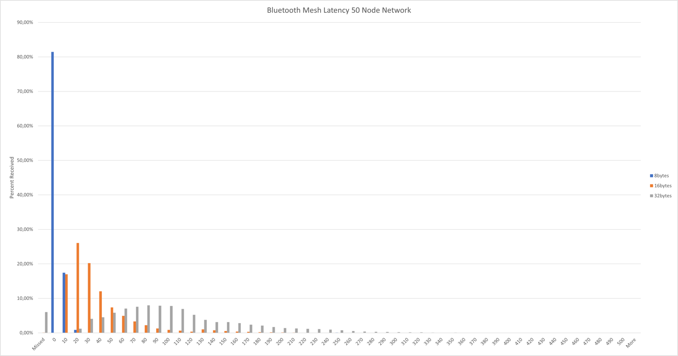
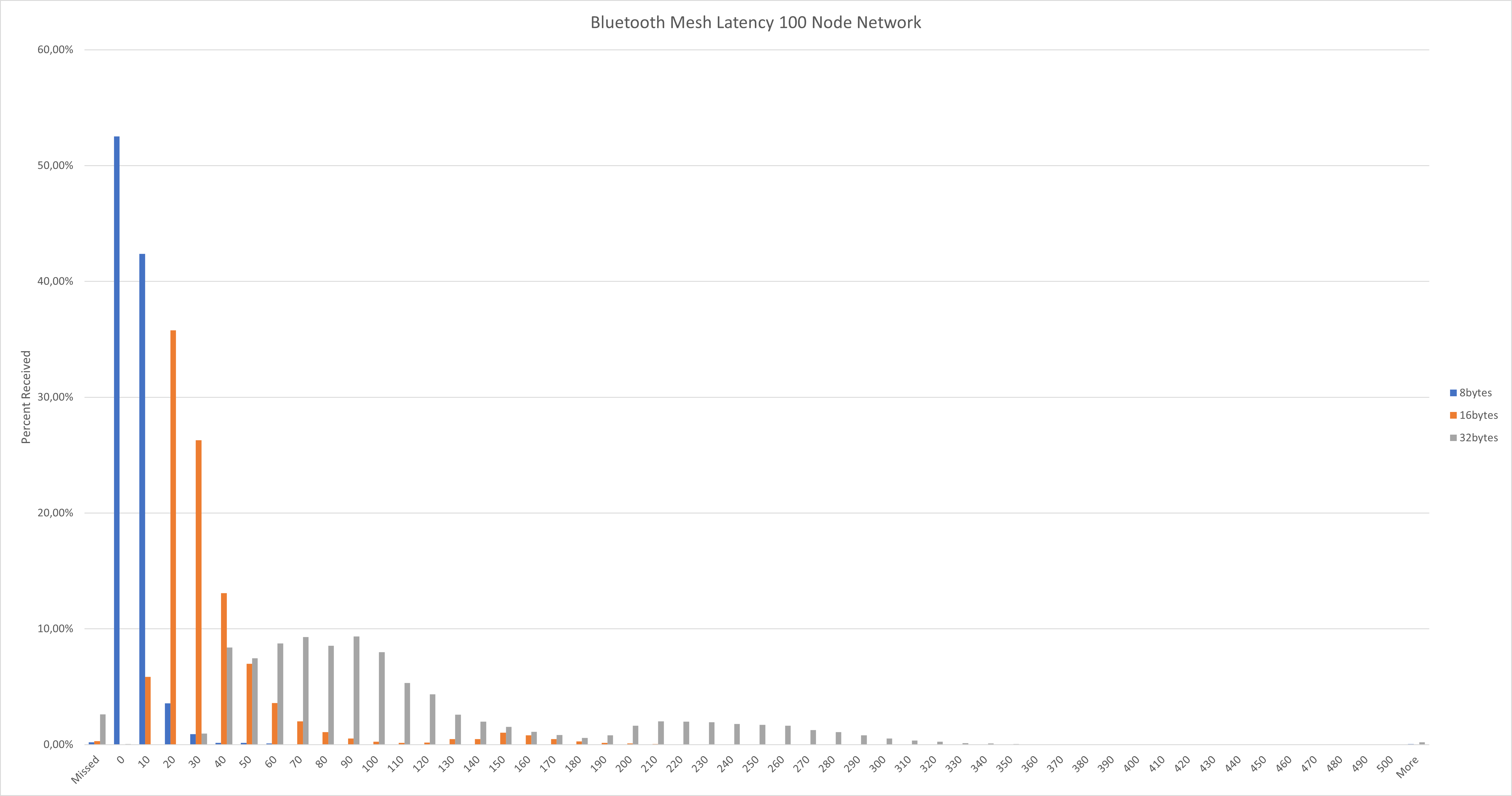
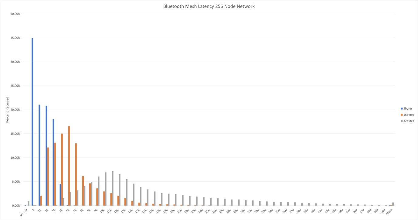
Results based on PDU size
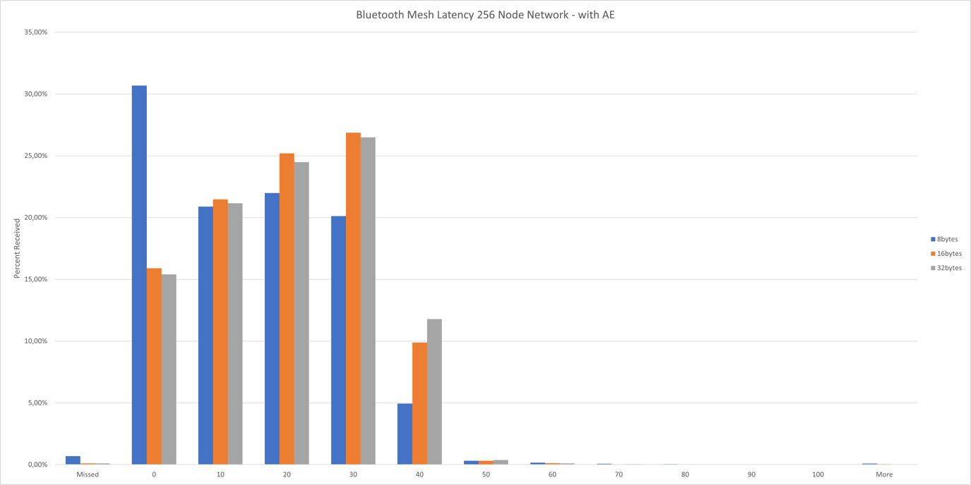
Results with Advertising Extension (AE)
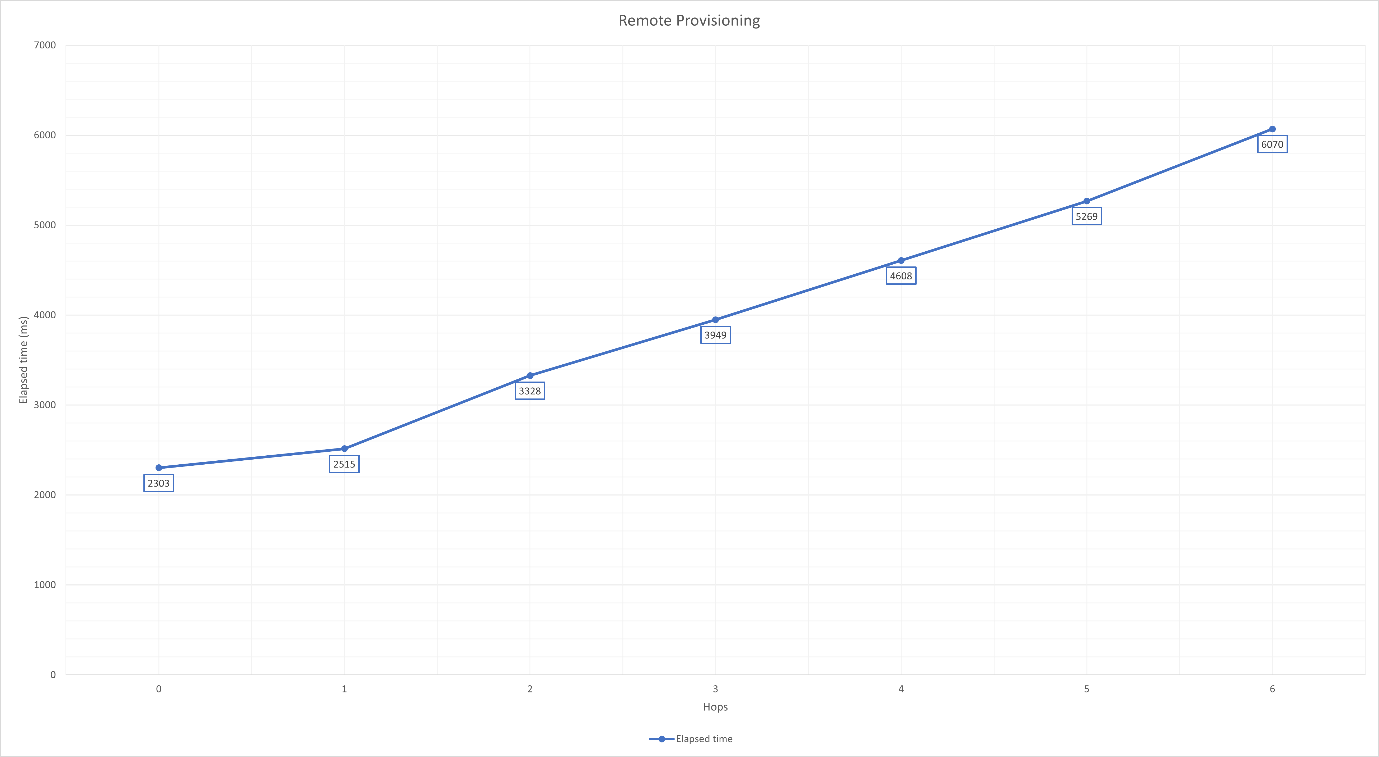
Remote Provisioning Performance#
To test the time of the remote provisioning based on the number of hops between the Remote Provisioning Server and Remote Provisioning Client, the test is carried out in the multi-hop RF-shielded test setup. The layout of the devices in the RF-shielded boxes can be seen on the next table. Note that each box can receive messages only from the neighboring boxes.
Box | 1 | 2 | 3 | 4 | 5 | 6 | 7 | 8 |
|---|---|---|---|---|---|---|---|---|
Devices in box | Remote Provisioning Server (S) Remote Provisioning Client (C) | Device0 (D0) | Device0 (D1) | Device0 (D2) | Device0 (D3) | Device0 (D4) | Device0 (D5) | Device0 (D6) |
Test Steps
The Remote Provisioning Server node (server = S) was provisioned traditionally by the Provisioner (Remote Provisioning Client = client = C). Relay mode was enabled on S.
The first device (device0 = D0) was provisioned remotely, this was the 0 hops case. Elapsed time was measured.
Relay mode was enabled on D0.
Remote Provisioning Server was initialized on D0.
Iterated through the remaining devices, where i started at 1:
Di started unprovisioned beaconing.
C opened link between Di and Di-1 using the Remote Provisioning Bearer.
Di was provisioned remotely. Elapsed time was measured.
Relay mode was enabled on Di.
Remote Provisioning Server was initialized on Di.
Only the time between starting the provisioning (issuing btmesh prov_provision_remote_device) and receiving the provisioned event (btmesh_evt_node_provisioned) was measured.
Over-The-Air Device Firmware Update (OTA DFU) Performance#
Introduction#
See Bluetooth Mesh Device Firmware Update for details on this feature. This document focuses more on the performance aspects of this feature, when running on larger, open-air networks.
Note that, while the target nodes are receiving the new image, the Mesh network remains operational, although the packet latency and loss rate might increase due to the increased amount of network traffic. It is also important to note that, if some target nodes fail to receive the new image, or the whole distribution fails for some reason, then the target nodes remain operational (running their old software), and the device firmware update procedure can be repeated.
It is possible to do multiple rounds of image distribution with different sets of target nodes, or with different distributor nodes, so it is not mandatory to update the whole network at once.
To test the Mesh OTA DFU feature, a software setup is used that would be easy to reproduce. That means such examples are used that are present in the release GSDK package, so no custom embedded application is needed to reproduce the results.
The image distribution is done using push transfer mode.
Distribution time is also measured with the Advertisement Extension (AE) feature enabled, which achieves better performance by increasing the network packet size. This is described in detail in AN1405: Bluetooth Mesh on Advertising Extensions.
Initiator Configuration#
As an initiator, the BT-Mesh Host DFU example application was used, running on a PC (tested on Windows and Linux as well), with a Bluetooth Mesh - NCP Empty v1.1 application on the embedded side, running on a BRD4186C board. The example application had the following changes in it:
New component added:
btmesh_stack_advertiser_extended
Parameters changed:
NVM3_DEFAULT_CACHE_SIZE:2200
SL_BT_CONFIG_BUFFER_SIZE:40000
NVM3_DEFAULT_NVM_SIZE:0x18000
SL_HEAP_SIZE:30000
SL_STACK_SIZE:11264
SL_BTMESH_CONFIG_MAX_PROVISIONED_DEVICES:155
SL_BTMESH_CONFIG_RPL_SIZE:155
Distributor Configuration#
As a distributor, the Bluetooth Mesh - SoC DFU Distributor example application was also running on a BRD4186C. It had the following changes:
New components added:
btmesh_event_log
btmesh_ae_server
btmesh_firmware_update_server
Parameters changed:
SL_BTMESH_CONFIG_MAX_RECV_SEGS:40
SL_BTMESH_CONFIG_MAX_SEND_SEGS:20
SL_BTMESH_FW_DIST_SERVER_MULTICAST_THRESHOLD_DEFAULT_CFG_VAL:1
SL_BTMESH_BLOB_TRANSFER_CLIENT_LOGGING_CFG_VAL:0
SL_BTMESH_BLOB_TRANSFER_CLIENT_LOG_BLOB_STATUS_MSG_CFG_VAL:0
SL_BTMESH_BLOB_TRANSFER_SERVER_DIST_TARGET_MAX_CHUNKS_PER_BLOCK_CFG_VAL:0x28
SL_BT_CONFIG_BUFFER_SIZE:60000
SL_HEAP_SIZE:50000
SL_STACK_SIZE:16384
SL_BTMESH_CONFIG_MAX_PROV_BEARERS:3
SL_BTMESH_FW_DIST_SERVER_MAX_NODE_LIST_SIZE_CFG_VAL:155
SL_BTMESH_BLOB_TRANSFER_CLIENT_MAX_SERVERS_CFG_VAL:155
SL_BTMESH_BLOB_TRANSFER_CLIENT_RETRY_TIME_MS_DEFAULT_CFG_VAL:1000
SL_BTMESH_CONFIG_RPL_SIZE:155
SL_BTMESH_BLOB_TRANSFER_CLIENT_MAX_BLOCKS_CFG_VAL:1024
The SAR Transmitter state (SAR Configuration Server model) was also modified:
SAR Multicast Retransmissions Count state = 2
SAR Multicast Retransmissions Interval Step = 25 ms
Target Nodes Configuration#
As target nodes, the Bluetooth Mesh - SoC Sensor Server was used both on BRD4186C and BRD4181B boards.
New components added:
btmesh_event_log
btmesh_ae_server
Parameters changed:
SL_BTMESH_BLOB_TRANSFER_SERVER_DFU_TARGET_MAX_BLOCK_SIZE_LOG_CFG_VAL:0xb
SL_BTMESH_BLOB_TRANSFER_SERVER_DFU_TARGET_MAX_CHUNKS_PER_BLOCK_CFG_VAL:0x28
Test Setup#
The distributor and the initiator node were chosen to be at the center of the network as much as possible, and close to each other. They were chosen to be in cluster number 8 (see Office and Test Network Conditions).
The tests were run with multiple network sizes and with or without the increased network PDU size (advertisement extension).
Two GBL files were used as update targets. One was a so called, dummy image that was smaller, and the nodes failed to verify it so would not apply it, and the other one was a real SOC Sensor Server GBL file that was much larger, and the nodes successfully applied it after the distribution. In the case of the dummy image, the test expected outcome was that the nodes would report a Verification Failed state at the end.
Summary of Important DFU Parameters#
Block Size and Block Count#
The Block size is negotiated during the distribution, and in this case is affected by the Max Block Size Log configuration value on the target nodes. Note that increasing the maximum block size will result in increased heap usage, which could be especially critical on the target nodes, because those are usually more limited in resources such as RAM, and the whole block needs to be stored there during distribution. The higher block size will increase the chunk size as well when the maximum chunk count cannot be satisfied with the preferred chunk size.
Larger chunks have a higher probability of being lost because they contain more segments. The penalty of lost chunks is higher because more segments need to be retransmitted.
The configuration parameter (on the target nodes):
SL_BTMESH_BLOB_TRANSFER_SERVER_DFU_TARGET_MAX_BLOCK_SIZE_LOG_CFG_VAL
Found in sl_btmesh_blob_transfer_server_config.h.
The Block Count was calculated from the BLOB Size and Block Size by ceil(BLOBSize / BlockSize) formula.
The Block Count affected the size of BLOB Transfer Status message and the number of Block Start & Query phases during BLOB Transfer.
N block results to ceil((23 + 8 x ceil(N / 8)) / 12) BLOB Transfer Status segments.
Firmware Distribution Server BLOB Multicast Threshold#
If the number of servers for any step exceeded or was equal to this number, then the group address was used; otherwise, servers were looped through one by one. Value of 0 disabled the feature.
Configuration parameter (on distributor):
SL_BTMESH_FW_DIST_SERVER_MULTICAST_THRESHOLD_DEFAULT_CFG_VAL
Found in sl_btmesh_fw_distribution_server_config.h.
Distributor Segmentation and Reassembly Multicast Retransmission Count / Interval#
These parameters determined how many times and what interval each segment of a segmented multicast message was repeated on the Distributor.
The fields that were modified were:
SAR Multicast Retransmissions Count State
SAR Multicast Retransmissions Interval Step
These parameters were configured by setting the SAR Transmitter state at the SAR Configuration Server model on the distributor.
Distributor Max Send Segs and Max Recv Segs#
Maximum number of simultaneous BT-Mesh segmented message transmissions and receptions.
Configuration parameters (on distributor):
SL_BTMESH_CONFIG_MAX_SEND_SEGS,
SL_BTMESH_CONFIG_MAX_RECV_SEGS
These parameters are found in sl_btmesh_config.h.
Test Procedure Steps#
The tests used the BT-Mesh Host DFU (btmesh_host_dfu) example script. For details about the following commands and their arguments, check the script help.
When the script runs the first time, it creates a default configuration file btmesh_host_dfu_cfg.ini. In this file, the following options are changed to accommodate the large network setup:
[common]
retry_max_default = 15
retry_interval_default = 4.0
retry_cmd_max_default = 15
retry_cmd_interval_default = 2.0
retry_multicast_threshold_default = 20
retry_auto_unicast_default = True
conf_retry_max_default = 10
silabs_retry_max_default = 15
silabs_retry_interval_default = 2.0
auto_conf_dcd_query = false
auto_conf_default_ttl = false
auto_conf_network_tx = false
auto_conf_sar = false
[dist_clt]
dist_retry_max_default = 100
dist_retry_multicast_threshold_default = 100
[network]
random_netkey = false
random_appkey = false
For further details, check the created INI file next to the script, where you will find these options with their default values and descriptions.
Target nodes are flashed with the modified SOC Sensor Server example application in batches of 5. Then, provisioning is done using advertisement bearer.
Groups are created from the nodes by executing the following commands:
group add -a 0 -g 0xC000 -s *Dist*[1] -m distributor -n DG1
group add -a 0 -g 0xC001 -s *Target*[0] -m target_node -n TNG1
The SAR configuration is done on the distributor node:
conf set --sar-tx-mc-retx-cnt 2 --sar-tx-mc-retx-int 25 --update *Dist*
If the advertisement extension feature is used for testing, then the following group is created, and configuration is done to set the PDU size to 227 bytes:
group add -a 0 -g 0xC002 -s *Node* -S SILABS_CONFIGURATION_SERVER -n AE1
conf ae -t 2m -p 227 --en --mdls *BLOB* -e 0 1 -g 0xFFFF -n *
The tested update target image is uploaded to the distributor:
dist upload -d *Dist*[1] -f 0x02ff:s:test_image -m s:0123 -T 1 example.gbl
The test starts a timer to measure the distribution time, and then executes the distribution:
dist start -d *Dist*[1] -f 0x02FF:s:test_image -G TNG1 -T 10 --poll-int 20
After the above command finishes, a table is printed out on the console with the target node statuses, and in case of a dummy image, the test expects the state to be “verification failed”, otherwise it expects “apply success”. The test measures the time of distribution when this table is printed out.
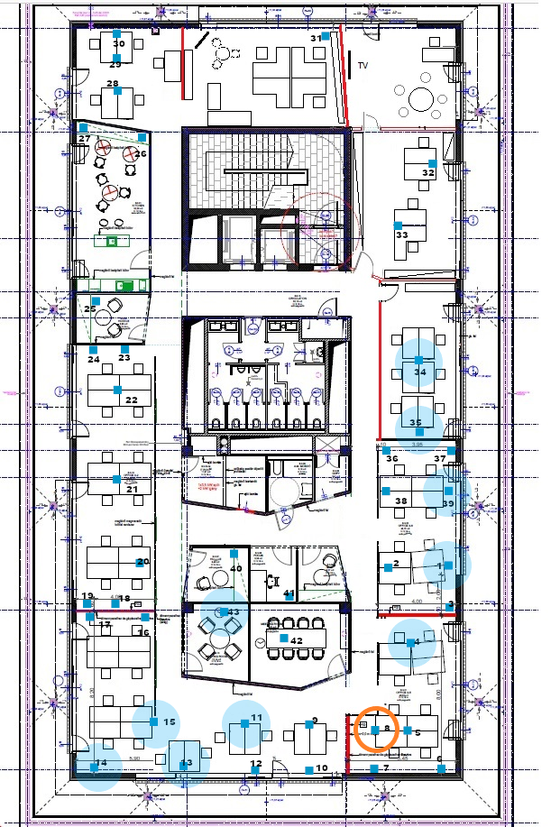
Network Topology#
For measuring the transfer speed, a 60-node Mesh network was created. There were no relay nodes in this setup. On the floor plans below, the orange circle signals the location of the initiator and distributor nodes. The pale blue areas are where the clusters (containing six devices each), indicated with solid blue boxes, were used to form the network.
60-Node Network Results#
Without the Advertising Extension feature enabled:
Image Type | Image Size (b) | Time (min) | Failed Node Count |
|---|---|---|---|
Dummy | 21,160 | 16.0 | 1 |
Real | 350,076 | 203.2 | 0 |
With the Advertising Extension feature enabled:
Image Type | Image Size (b) | Time (min) | Failed Node Count |
|---|---|---|---|
Dummy | 21,160 | 12.5 | 0 |
Real | 350,076 | 158.2 | 0 |