Simplicity Studio 5 and Bluetooth Mesh#
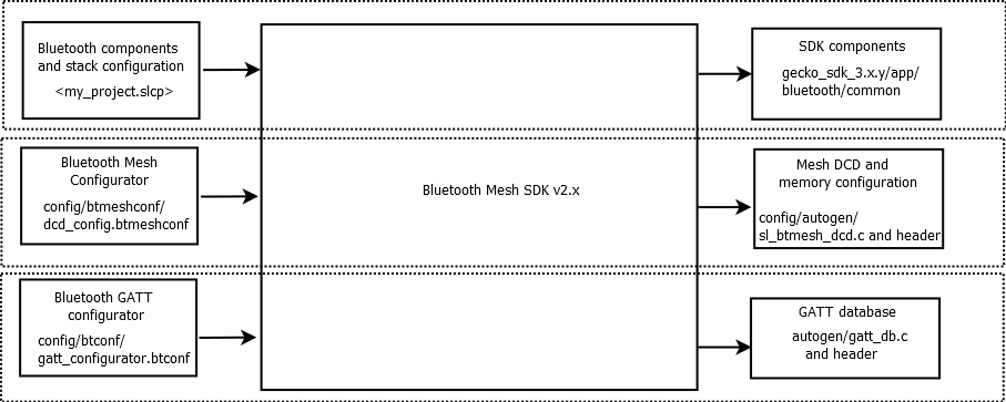
A number of new features and architecture changes were introduced beginning with Bluetooth Mesh SDK v2.0 and Simplicity Studio 5. The features supported are backward compatible with applications built with the Bluetooth Mesh SDK v1.x, although the API in use is different. Projects generated with the Bluetooth Mesh SDK v2.0 and higher can be configured via the three following input parameter tools:
Project file, using the slcp extension (silicon labs component project) (For the Mesh components)
Bluetooth mesh configurator (for DCD configuration)
Bluetooth GATT configurator (for Mesh services)
Note: Unlike versions 1.x and lower, the current version of the Bluetooth Mesh SDK does not have a Generate control. Project files are generated and updated as you make changes and save the updates in the Component Configurator.
Bluetooth Mesh Components#
Upon creation of a Bluetooth Mesh project in Simplicity Studio 5, at least three tabs open automatically:
The GATT Configurator (gatt_configuration.btconf)
The slcp file or Project Configurator (<projectname>.slcp
The Bluetooth Mesh Configurator (dcd_config.btmeshconf).
If the example has documentation, the project opens on a readme tab.

The GATT Configurator is the same for both Bluetooth and Bluetooth mesh projects. GATT Configurator User’s Guide for Bluetooth® LE and Bluetooth Mesh describes how to configure the GATT database.
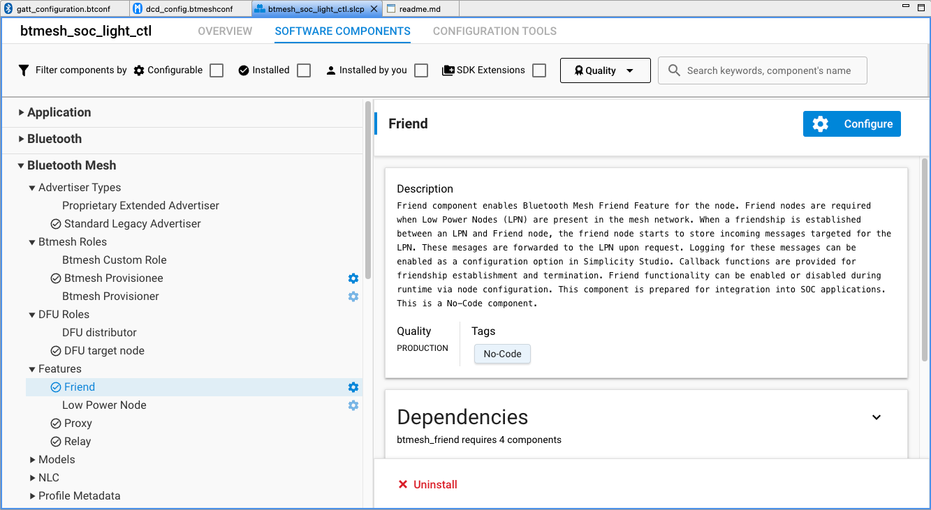
The Project Configurator and associated component editor allows you to install/uninstall and configure components.
The Bluetooth Mesh Configurator provides access to Device Composition Data (DCD). This contains information about a Bluetooth mesh node, the elements it includes, and the supported models. DCD exposes the node information to a configuration client so that it knows the potential functionalities the node supports and, based on that, can configure the node.
Bluetooth Mesh Configurator#
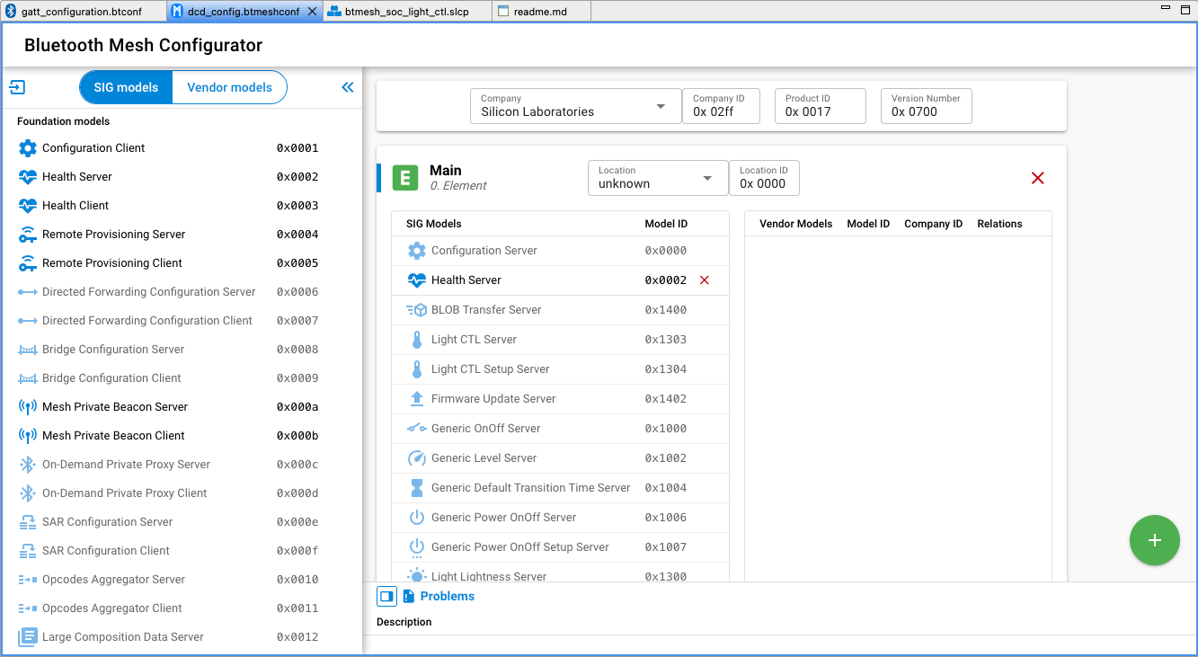
To access Device Composition Data, open the Bluetooth Mesh Configurator on the dcd_config.btmeshconf tab. The Device Composition data is presented in three areas: device information, elements, and models.
Device Information#
The device information card contains four fields, shown in the following figure.

The Company field is linked to the Company ID field, changing one will automatically change the other as a result. The meaning of each field is shown in the following table.
Field Name | Notes |
|---|---|
Company | The company name in the list containing all the registered companies in Bluetooth SIG |
Company ID | 16-bit company identifier assigned by the Bluetooth SIG |
Product ID | 16-bit vendor-assigned product identifier, vendor-specific |
Version Number | 16-bit vendor-assigned product version identifier, vendor-specific |
A list of companies and their unique identifier can be found on the Bluetooth SIG site.
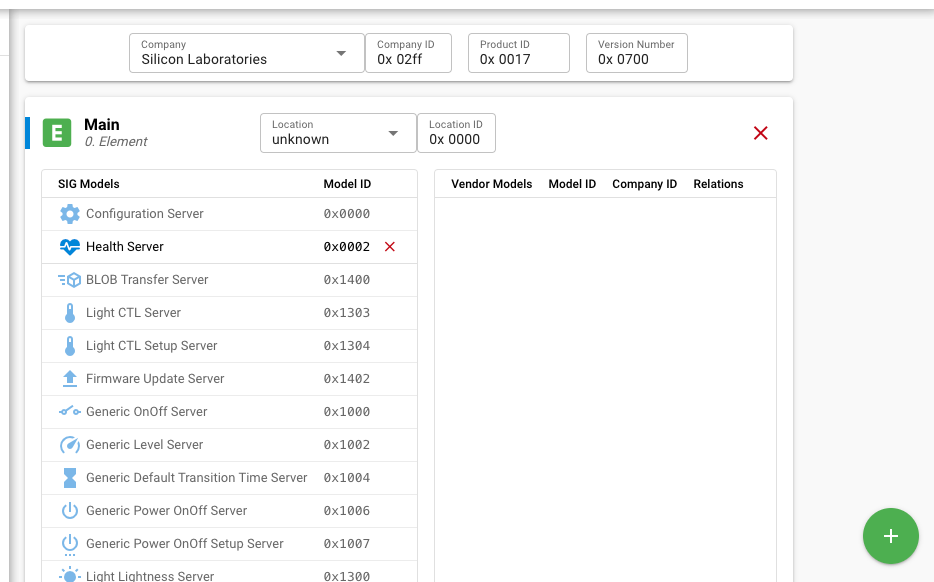
Elements#
An element is an addressable entity within a node. Each node can have one or more elements, the first called the primary element and the others called secondary elements. Each element is assigned a unicast address during provisioning, so that it can be used to identify which node is transmitting or receiving a message. The primary element is addressed using the first unicast address assigned to the node, and the secondary elements are addressed using the subsequent addresses. Both primary and secondary elements have a dedicated card, such as that shown in the following figure, through which they can be configured. Click the green plus symbol to add an element or select an element and click the red X symbol to remove it.
Models#
A model defines the basic functionality of a node. A node may include multiple models. A model defines the required states, the messages that act upon those states, and any associated behaviors.
Models may be defined and adopted by the Bluetooth SIG and may also be defined by vendors. Models defined by the Bluetooth SIG are known as SIG-adopted models, and models defined by vendors are known as vendor models. SIG-adopted models are identified by a 16-bit model identifier and vendor models are identified by a 16-bit vendor identifier and a 16-bit model identifier.
The Bluetooth Mesh Configurator supports configuring both SIG-adopted models and vendor models through separate editors selected by the SIG models and Vendor models selector just below the Bluetooth Mesh Configurator -text.
SIG-Adopted Model Editor#
Add SIG Models via Components#
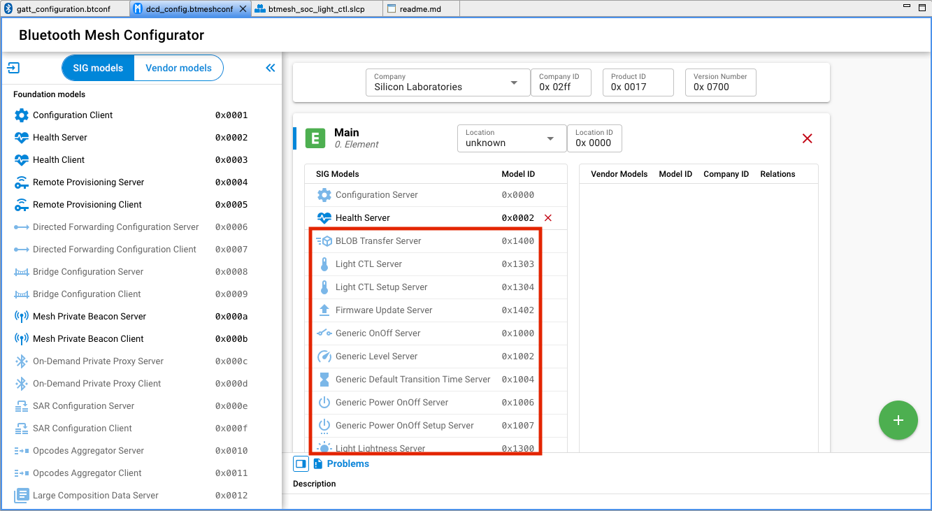
If you are using the provided model components that automatically bring in the source/header files, libraries, and configurations to the project, and also contribute the model to the DCD, you cannot edit or delete the model from the DCD manually. The model is greyed out, as shown in the following figure. In this case, all the model implementations will be generated to the project. You can modify the callbacks to adjust the application to your use case.
Edit SIG Models Manually#
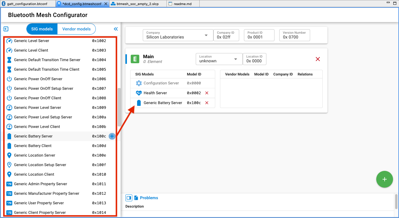
The DCD editor displays the information list of available models in SSv5 on the left side. Because models are added and configured as components, they are not editable in the Mesh configurator. To build the DCD from a clean slate, for example when adding specific models to an element, uninstall all model components manually and then edit the DCD.
To delete a model, select it and click the red X symbol. To add a SIG-adopted model, drag and drop the model from the left model pool to the SIG Models table in the correct element. A list of all the SIG-adopted models is displayed, and you can choose the one that is needed. Note that, although all the SIG-adopted models are listed, not all of them are currently supported by the Bluetooth Mesh SDK. For the information on the supported models, see the SDK release notes.
Due to the extension mechanism of models mentioned above, attention must be paid when adding models to your project:
When adding a model that is not a root model, in other words an extended model, all the models it extends from should also be added. The Bluetooth Mesh Model Specification has the detailed definition of the models’ relationships. For example, to add a Light Lightness Server model, the Generic Power On/Off Server model and the Generic Level Server model must also be present in the settings, because the Light Lightness Server model is extended from them.
One element can only have one instance of a model. For example, if both model A and Model B are extended from Model C, you cannot add them both to a single element because it would require two Model C instances. The appropriate way to achieve this is to have two elements, and put model A and model C in one element and model B and model C in the other element. For example, the light example in the Bluetooth Mesh SDK has two elements in order to have two Generic Level Server model instances.
In addition to the above points, follow the points below when editing the model setting of a node.
The configuration server model must be supported by a primary element and must not be supported by any secondary elements.
To develop a provisioner, add at least the configuration client model in your project, and it should be in the primary element.
The health server model must be supported by a primary element and may be supported by any secondary elements.
If the health client model is supported, it must be supported by a primary element and may be supported by any secondary elements.
Vendor Model Editor#
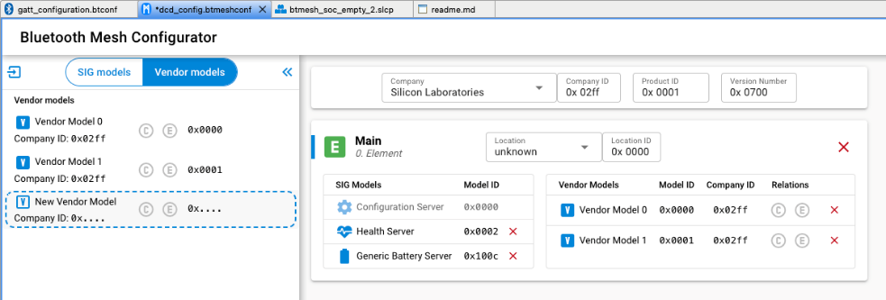
The Vendor models give you more flexibility when developing products not covered by the SIG-adopted models. Vendors can define their own specification in these models, including states, messages, and the associated behaviors. The vendor model editor is shown in the following figure. The ID field contains the 32-bit vendor identifier and model identifier. The two least significant bytes of the ID are the vendor ID and the two most significant bytes are the model ID. In the following figure, 0x02FF is the vendor ID for Silicon Labs, and 0x0021 and 0x0022 is the model ID.
Do one of the following:
Click New Vendor Model to create a new vendor model
Select a model to edit it
Click the + symbol to add it to a element
Click the red X from the element to remove it.
Bluetooth Mesh Stack#
The Bluetooth Mesh SDK provides several SRAM and internal flash consumption optimization options. Memory should be configured to allocate the appropriate amount of resource needed, so the space left for application usage is optimized. The stack memory configuration can be tuned by configuring the Bluetooth Mesh Stack component.
The following figure shows the available configuration options:
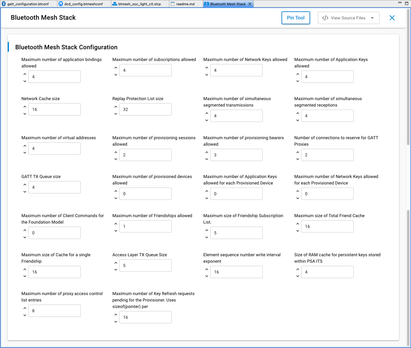
All configuration options affect RAM consumption. The stack allocates various structures at startup based on the values entered and uses the allocated memory during operation.
Some configuration options also affect consumption of persistent storage in internal flash. The stack allocates space in persistent storage based on the configuration option values at start up. The persistent storage implementation used by the Bluetooth Mesh stack is either NVM3 (recommended, default on series 2) or PS Store. For more details, see Using Third Generation Non-Volatile Memory (NVM3) Data Storage.
The following table summarizes the configuration options:
Configuration Option | Description | Stored Persistently | Notes |
|---|---|---|---|
Maximum number of Network Keys allowed | The maximum number of network keys that can be stored (see 2.2.1 Network and subnets and 2.3.9 Security of Mesh Protocol 1.1). | Yes | No larger than 4. |
Maximum number of Application Keys allowed | The maximum number of application keys that can be stored (see 2.2.1 Network and subnets and 2.3.10 Security of Mesh Protocol 1.1.). | Yes | No larger than 4. |
Maximum number of application bindings allowed | The maximum number of application keys that can be bound to a model. | Yes | No larger than the value of ‘Maximum number of Application Keys allowed’. |
Maximum number of subscriptions allowed | The maximum number of addresses that the device can subscribe to (see 3.7.5.2 Subscribe of Mesh Protocol 1.1). | Yes | No larger than 255. |
Maximum number of provisioned devices allowed | The maximum number of devices that can be provisioned by this device. | Yes | Only applicable if the device is in provisioner role, no larger than 512. Set to 0 for node role. |
Replay Protection List size | The replay protection list size (see 3.9.8 Message replay protection of Mesh Protocol 1.1). | Yes | Set to equal or greater than the expected number of elements the device will communicate with. Otherwise, the node cannot receive a message from any new node if the list is already full. Must be no larger than 4096 and divisible by 16. |
Maximum number of virtual addresses | The maximum number of virtual addresses the models on the device can publish or subscribe to (see 2.3.5 Addresses and 3.4.2.3 Virtual address of Mesh Protocol 1.1). | Yes | Set to 0 if virtual address not used. |
Maximum number of Network Keys allowed for each Provisioned Device | The maximum number of network keys on the peers provisioned by this device. | Yes | Only applicable if the device is in provisioner role. |
Maximum number of Application Keys allowed for each Provisioned Device | The maximum number of application keys on the peers provisioned by this device | Yes | Only applicable if the device is in provisioner role. |
Maximum number of simultaneous segmented receptions | The maximum number of segmented messages that can be received in parallel (see 3.5.3 Segmentation and reassembly of Mesh Protocol 1.1). | No | Set to a low number if little segmentation is used. |
Maximum number of simultaneous segmented transmissions | The maximum number of segmented messages that can be sent in parallel (see 3.5.3 Segmentation and reassembly of Mesh Protocol 1.1). | No | Set to a low number if little reassembly is used. |
Maximum number of provisioning sessions allowed | The maximum number of simultaneous provisioning sessions the device supports. | No | Set to 1 if the device is in node role. For the provisioner role, set to greater than 1 if provisioning multiple devices simultaneously. |
Maximum number of Client Commands for the Foundation Model | The maximum number of commands that Configuration and Health client can send in parallel (see 4 Foundation models of Mesh Protocol 1.1). | No | Only applicable if the device is in provisioner role. |
Network Cache size | The network message cache size (see 3.4.6.5 Network Message Cache of Mesh Protocol 1.1). | No | Network density-dependent. |
Number of connections to reserve for GATT Proxies | The maximum number of GATT connections for PB-GATT and GATT bearers. | No | Can be 0 if PB-GATT and GATT bearers are not supported. |
Maximum number of provisioning bearers allowed | Number of provisioning bearers (see 5.2 Provisioning bearer layer of Mesh Protocol 1.1). | No | Number of supported provisioning bearers, PB-ADV, PB-GATT and/or PB-REMOTE. Not greater than 3. |
Maximum number of Friendships allowed | The maximum number of friendships that can be established (see 2.3.12 Friendship of Mesh Protocol 1.1). | No | Only applicable for friend node. |
Maximum size of Total Friend Cache | The maximum number of messages a friend node can cache. (see 3.5.5 Friend Queue of Mesh Protocol 1.1). | No | Only applicable for friend node. |
Maximum size of Cache for a single Friendship | The maximum number of messages a friend node can cache for a single low-power node (see 3.5.5 Friend Queue of Mesh Protocol 1.1). | No | Only applicable for friend node. |
Maximum size of Friendship Subscription List | The maximum number of addresses that can be stored in the Friend Subscription List. | No | Only applicable for friend node. |
GATT TX Queue size | Queue size for messages over GATT bearer. | No | Connection interval-dependent. |
Access Layer TX Queue Size | The maximum number of messages that can be queued in the Access layer (see 3.7.3.1 Transmitting an access message of Mesh Protocol 1.1). | No | Default 5 |
Element sequence number write interval exponent | The latest Network PDU sequence numbers are stored into flash from time to time as defined by this setting for reset or power off situations. | From 0 to 23, default 16. | |
Size of RAM cache for persistent keys stored within PSA ITS | PSA ITS (internal trusted storage) Mesh encryption keys RAM cache to increase runtime performance. | From 0 to 544, default 16. | |
Maximum number of proxy access control list entries | Define the number of proxy access control list entries. | Default 8 | |
Maximum number of Key Refresh requests pending for the Provisioner | Define the maximum number of concurrent config client requests to nodes during Key Refresh | Default 16 |
To download Mesh Protocol 1.1 (currently a draft version d1.1r20), go to https://www.bluetooth.org/DocMan/handlers/DownloadDoc.ashx?doc_id=554899.
Maximum Number of Network Keys Allowed#
The value determines the maximum number of network keys that can be stored in the device. For the Bluetooth Mesh SDK v5.x, the maximum is 4, which means a device can support no more than 4 subnets. A node should stay in the network(s) it was in after a power cycle, so the network keys and the related information should be stored persistently. Because of the key refresh procedure requirements, each network key will hold 2 values – the current network key and the old network key.
Maximum Number of Application Keys Allowed#
The value determines the maximum number of application keys that can be stored in the device. For the Bluetooth Mesh SDK v5.x, the maximum number is 4, which means a device can support no more than 4 application keys no matter which network keys they are bound to. The application keys and the related information should be stored persistently. Because of key refresh procedure requirements, each application key will hold 2 values – the current application key and the old application key.
The maximum application key number should be set close to the expected number of application keys that will be used in a network.
Maximum Number of Application Bindings Allowed#
If a message is successfully decrypted by the upper transport layer with an application key, the decrypted message and the application key information will be delivered to the access layer. The access layer will check if the message is used by the model on the node, and then check if the application key is bound to the model. This value decides the maximum number of application keys that can be bound to a single model. The binding information will be stored persistently. Because the bindings are model-specific, the total amount of flash usage is multiplied by the number of models on the node.
The number of bindings should not be set larger than the number of application keys that can be stored on the device. It can be set to a smaller number if it is expected that each model will be bound to only one or a few keys.
Maximum Number of Subscriptions Allowed#
Each model can have a separate or a shared subscription list, if it supports subscription. This value determines the subscription list size, in other words, how many addresses can be subscribed by a model. All the subscription lists will be stored persistently, because the extended models share the same subscription list with their root model. The real amount of space depends on what models are on the device.
The number of subscriptions should be set to the maximum expected number of subscriptions to be made to each model, or slightly larger.
Maximum Number of Provisioned Devices Allowed#
This setting is applicable only when the device is in the provisioner role. The value determines the maximum number of devices the provisioner can provision to the network. The best number for this setting should be the maximum expected network size. For Bluetooth Mesh SDK v5.x, the maximum value is 512, which means the maximum network size supported by the stack is 512 nodes.
Because a node cannot provision any devices into the network and doesn’t have the device database, set to 0 for devices in node role.
Replay Protection List Size#
A message sent by a legitimate originating element can be passively received by an attacker and then replayed later without modification. This is called a replay attack. Because the originating element has encrypted and authenticated the message using the correct keys, the receiver cannot determine whether it is under a replay attack solely by performing the message integrity checks.
To increase protection against replay attacks, each element increases the sequence number for each new message that it sends, and the receivers keep track of the largest sequence number they have received from each originating element. This bookkeeping is called the replay protection list. If a valid message has been received from an originating element with a specific sequence number, any future messages from the same originating element containing sequence numbers less than or equal to the last valid sequence number are very likely replayed messages and should be discarded. Therefore, messages are delivered to the access layer in sequence number order.
Due to security concerns, entries in the replay protection list cannot be reused, which means there is no way to delete or clear an entry if it has already been used. No Least Recently Used algorithm is used in this list because it brings potential security risks. It is explicitly specified in the Mesh Protocol 1.1. If a node does not have enough resources to perform replay protection for a given source address, then the node shall discard the message immediately upon reception.
Furthermore, because nodes could be removed from the network and new devices will be added to the network, the replay protection list should be set to the maximum number of elements the device will communicate with, which could be larger than the maximum network size in this case. For example, assume the network size is 5, contains devices 1-5, and they have already communicated with each other. The replay protection list on device 1 should contains device 2-5, which occupies 4 entries. Then, if devices 2-5 are removed from the network and devices 6-9 are added to the network, device 1 will need 4 more entries in the replay protection list to be able to communicate with devices 6-9. In this scenario, device 1 needs 8 replay protection entries, which is larger than the network size of 5.
The replay protection list is stored persistently. The number of replay protection list entries should be set to the number of peers a node is expected to communicate with, rounded up to the nearest number divisible by 16.
Maximum Number of Virtual Addresses#
This setting determines the maximum number of virtual addresses the models on the device can publish or subscribe to. A virtual address is a multicast address and can represent multiple elements on one or more nodes. Each virtual address logically represents a Label UUID, which is a 128-bit value that does not have to be managed centrally. Each message sent to a Label UUID includes a message integrity check value containing the full Label UUID that is used to authenticate the message. To reduce the overhead of checking every known Label UUID, a hash of the Label UUID is used. Although the virtual address is 2 bytes, the 128-bit label UUID value should be stored persistently because the full data needs to be used for decrypting the messages sent to virtual addresses.
The number of virtual addresses should be set to as small a number as possible, or zero if it is expected that virtual addresses are not used. The current Mesh Model specification does not require the use of virtual addresses, so at the moment they are used only in vendor-specific contexts.
Maximum Number of Network Keys Allowed for each Provisioned Device#
This setting is only used during the key refresh procedure. The provisioner should persistently store the states of network keys of the nodes participating in the key refresh procedure. This value determines the maximum number of network keys that can be included in the key refresh procedure, in other words, how many network keys can be refreshed one time.
This only applies to a provisioner. Set to 1 if you only want to refresh one network key at a time, or a higher value if the use case needs to refresh more than one network key at once. Set to 0 for devices in node role.
Maximum Number of Application Keys Allowed for each Provisioned Device#
This setting is only used during the key refresh procedure. The provisioner should persistently store the states of application keys of the nodes participating in the key refresh procedure. This value determines the maximum number of application keys that can be included in the key refresh procedure, in other words, how many application keys can be refreshed one time.
This only applies to a provisioner. Set to 1 if you only want to refresh one application key at a time, or a higher value if the use case needs to refresh more than one application key at once. Set to 0 for devices in node role.
Maximum Number of Simultaneous Segmented Receptions#
Due to the packet size limitation in Bluetooth Mesh, a message may be sent unsegmented or segmented, depending on the message payload size. For the transport layer to receive the segmented message, it has to cache the received segments before all the segments are received successfully. This setting determines the maximum segmented messages that can be received concurrently. Note, this does not define how many segmented packets in a message, but how many segmented messages no matter how many packets the message is segmented into. For example, if the setting is 3, the node is able to receive segmented message A, B, and C simultaneously, no matter how messages A, B, and C are segmented into A1, B1, C1 … An, Bn, Cn. The maximum number that a message can be segmented into is defined in the Mesh Protocol specification.
A device with standard models rarely receives segmented messages (encryption key deployment being one example) so a low number can be used if none of the vendor models need segmentation.
Maximum Number of Simultaneous Segmented Transmissions#
Due to the packet size limitation in Bluetooth Mesh, a message may be sent unsegmented or segmented, depending on the message payload size. For the transport layer to send the segmented message, it has to cache the whole message before all the segments are sent and acknowledged successfully. This setting determines the maximum segmented messages that can be sent concurrently. Note, this does not define how many segmented packets are in a message, but how many segmented messages no matter how many packets the message is segmented into. For example, if the setting is 3, the node is able to send segmented message A, B, and C simultaneously, no matter how messages A, B, and C are segmented into A1, B1, C1 … An, Bn, Cn. The maximum number that a message can be segmented into is defined in the Mesh Protocol specification.
A device with standard models rarely sends segmented messages (encryption key deployment being one example) so a low number can be used if none of the vendor models need segmentation.
Maximum Number of Provisioning Sessions Allowed#
Provisioning is session-based. A provisioner does not necessarily need to provision the devices serially, but instead can provision the devices in parallel. This setting determines the maximum number of provisioning sessions that can happen concurrently. For example, in an ideal scenario, if the value is 1 and each provisioning takes 3 seconds, then provisioning 100 devices takes 300 seconds. If you set this value to 5, then it takes 60 seconds in total to provision all 100 nodes. Although in practice the time will be affected by packet collision, it should still be much less than 300 seconds.
This does not need to be over 1 for devices in node role because a device cannot be provisioned by multiple provisioners at the same time. It may be over 1 for a provisioner that provisions devices concurrently and it significantly reduces the time for provisioning a large network.
Maximum Number of Client Commands for the Foundation Model#
After provisioning a device into a network, the first step is probably to configure the node because an unconfigured node is not functional. The configuration starts by the configuration client model sending a command to the configuration server on the node, followed by a reverse status message if applicable. The current Mesh Protocol 1.1 specification only defines several foundation client models. This setting determines how many commands can be sent by the foundation client models concurrently before the status message is received. For example, in an ideal scenario, if the value is 1 and the configuration to add an application key to a node takes 3 seconds, then adding the application key to 100 devices takes 300 seconds. If you set this value to 5, then it takes 60 seconds in total to add the application key to all 100 nodes. Although in practice the time will be affected by packet collision, it should still be much less than 300 seconds.
This is not applicable and should be set to 0 for devices that do not have foundation client models. It may be over 1 for a provisioner that configures devices concurrently and it significantly reduces the time for configuring a large network.
Network Cache Size#
The network message cache is used to reduce unnecessary security checks and excessive relaying. It is a list of all the information about recently seen network packets. When a network PDU is received and already in the network message cache, for example because of network retransmission, it will be discarded immediately without processing. If a received network PDU is not in the network message cache, its information should be added to the network message cache and be further processed.
Note, this network message cache is different from the replay protection list. It is not for security. When the Network Message Cache is full and an incoming new Network PDU needs to be cached, an incoming new Network PDU should replace the oldest Network PDU that is already in the Network Message Cache.
The suitable value is dependent on expected network density, node configuration, and traffic frequency. For example, if network layer repetition is configured on, with an interval that allows multiple messages to be injected to the network by other nodes during the interval, the cache should be large enough to handle this and not flush the previous Tx before the repetition.
Number of Connections to Reserve for GATT Proxies#
This setting determines the maximum number of GATT connections the device can establish concurrently. For devices in an unprovisioned state, the GATT connections can be used for establishing the PB-GATT bearer so that provisioning can be done over GATT. For devices in a provisioned state and supporting Proxy, the GATT connections can be used for establishing the proxy connections so that all the communication can go over GATT bearers.
If devices do not support the Proxy feature or provisioning over a GATT connection, it can be set to 0. The number of proxy filters is limited to 16 per connection.
Maximum Number of Provisioning Bearers Allowed#
Three provisioning bearers are defined in the Mesh Protocol 1.1: PB-ADV, PB-GATT, and PB-REMOTE. This setting should be consistent with the number of provisioning bearers supported by the device. An unprovisioned device may support PB-ADV and may support PB-GATT. Supporting both PB-ADV and PB-GATT is strongly recommended. A Provisioner must support at least one of PB-ADV or PB-GATT. Supporting PB-ADV is strongly recommended. PB-REMOTE is required for the remote provisioning in the provisioner (the remote provisioning client controlling the remote provisioning operation) and the remote provisioning server (communicating with the unprovisioned node using PB-ADV or PB-GATT).
The value should not be set to larger than 3 as only 3 available provisioning bearers are defined in Mesh Protocol 1.1. It is also not recommended to set it to 0, as provisioning is mandatory for devices to be added to a network.
Maximum Number of Friendships Allowed#
In principle, all the nodes in the Bluetooth Mesh network should listen for incoming packets at the highest possible duty cycle to avoid losing packets. But a battery-powered device must sleep to save power, so it must be associated with an always-on device that stores and relays messages on its behalf. The relationship between the always-on node and the battery-powered nodes is friendship.
This setting is only applicable for nodes that support the friend feature. It determines the maximum number of friendships it can establish, in other words, the maximum number of low-power nodes it can establish the friendship with concurrently. Set to 0 if the node does not support the friend feature.
Maximum Size of Total Friend Cache#
As mentioned in Section Maximum number of Friendships allowed , a low-power node needs to establish a friendship with a neighboring friend node. The friend node will cache the message targeted to the low-power node and the low-power node can periodically poll the friend node for messages. All the cached messages are stored in the Friend Queue. This setting determines the Friend Queue size, that is, how many messages in total it can store for all the low-power nodes it established friendship with. It is only applicable for nodes which support the friend feature. Set to 0 if the node does not support friend feature.
Maximum Size of Cache for a Single Friendship#
The Maximum size of Total Friend Cache setting (section Maximum number of Friendships allowed ) determines the maximum number of messages that can be stored in the Friend Queue in total. This setting determines the maximum number of messages that can be stored in the Friend Queue for a single Friendship. Because of the difference among use cases, the requirement for the number of messages to be stored could vary from one low-power node to another. This setting and the Maximum size of Total Friend Cache setting make the allocation of the Friend Queue dynamic when establishing friendships, and the use of the Friend Queue more efficient. This setting is only applicable for nodes that support the friend feature and must be set equal to or less than the Maximum size of Total Friend Cache setting. Set to 0 if the node does not support the friend feature.
Maximum Size of Friendship Subscription List#
As mentioned in section Maximum number of Friendships allowed, the friend node needs to cache the message targeted to the low-power node that it established the friendship with. The low-power node would like to receive two types of messages. One is the message with the destination address to be the unicast address(s) on the low-power node. The other is the addresses that the low-power node subscribes to. In order to cache the messages designated for the addresses that the low-power node subscribes to, the friend node needs to maintain a list of the low-power node’s subscription addresses. A low-power node could update the subscription list by adding addresses to the list or removing addresses from the list. This setting determines the maximum addresses that can be stored in the subscription list on the friend node for a single low-power node.
GATT TX Queue Size#
This setting determines the number of PDUs that may be pending transmit on the GATT bearer. The value may be small for a node that is only configured over a GATT proxy bearer (default is 4). It may need to be larger for a node that acts as a GATT proxy between the network and a legacy device, and where the connection interval for the GATT connection is long.
Access Layer TX Queue Size#
As defined in 3.7.3.1 Transmitting an access message of Mesh Protocol 1.1, the message in response to a received message should be sent after a random delay. Those messages need to be queued in the stack waiting for the timing to be sent. This setting determines the maximum number of access layer messages that can be queued, in other words, how many replies can be queued for sending concurrently. For nodes that do not have server models, this value can be set to a low value as messages will only be cached during the configuration phase. For server model nodes, this value should be set according to the requirements of the actual use case.
Element Sequence Number Write Interval Exponent#
Each network PDU originating from a device must be sent with an increasing sequence number. To maintain this when the device is reset or powered off, the latest sequence numbers are stored in flash with a frequency defined by this setting. The setting defines the sequence number writing interval as a power of two exponent. For example, a value of 10 would mean 1024 (2 to the 10th power). To avoid excessive flash wear, the interval should be relatively high on a device that generates a lot of traffic, and it can be set relatively low on a device that generates little traffic. Range from 0 to 23, the default is 16.
Size of RAM Cache for Persistent Keys stored within PSA ITS#
When PSA internal trusted storage (ITS) is used to store the Mesh encryption keys, a RAM cache should be set up to increase runtime performance. The size of the cache should be set according to the expected use of application and device keys. For a node, it can be set to the number of application keys times two (to accommodate both key variants during a key refresh); for a Provisioner, it should be set to the number of application keys times two (to accommodate both key variants during a key refresh) plus a fraction of the expected number of device keys that will be stored. For devices that do not use PSA ITS, the setting is ignored. Range from 0 to 544, the default is 16.
Maximum Number of Proxy Access Control List Entries#
Define the number of proxy access control list entries. The default is 8.
Maximum Number of Key Refresh Requests Pending for the Provisioner#
Define the maximum number of concurrent config client requests to nodes during Key Refresh. Uses sizeof(pointer) per request statically, each pending request is dynamically allocated. The default is 16.
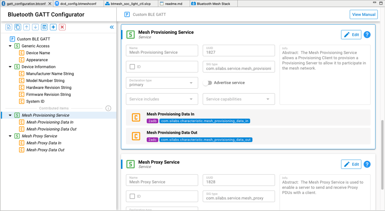
Bluetooth GATT Configurator#
The Bluetooth Mesh technology is primarily based on BLE advertisements that use a specific Mesh Message AD (Advertising Data) type. Some nodes, though, might not be able to advertise using the Mesh Message AD type, and instead require a GATT connection to send and receive network packets, provisioning data and so on.
The Bluetooth Mesh specification defines two GATT services dedicated to mesh networks for good operation in a connected context:
The Mesh Provisioning service (0x1827)
The Mesh Proxy service (0x1828)
A device may support the Mesh Provisioning Service or the Mesh Proxy Service or both. If both are supported, only one of these services should be exposed in the GATT database at a time. For more details on those services, refer to the Bluetooth Mesh Protocol specification (section 7).
In the current Silicon Labs’ Bluetooth Mesh SDK, both services are present in the GATT database by default when creating a project.
The services have their capabilities disabled by default because they are Bluetooth Mesh-specific.
In certain cases, typically when provisioning through a gateway running a third party or open source stack like BlueZ or Zephyr OS, it is necessary to have the services advertised. This simply indicates to the provisioner that the Mesh services are supported by the node.
Note that, by default, when working with the current Bluetooth Mesh SDK, this is not necessary.
Enabling and disabling service advertisement can be done through just editing the service.