SE Command List#
This application note does not include a complete list of commands for DCI. The following sections contain information about each command's operation and arguments for DCI production programming. The command and response payload may be device-specific (e.g., Initialize OTP and Get Status).
For more information about secure boot, see Series 2 Secure Boot with RTSL. For more information about debug lock and secure debug, see Series 2 Secure Debug.
SE Image Check#
This command can be used to check the SE image before starting the upgrade process, in order to be able to abort early if the image is invalid or inapplicable.
Note: This command is only available on SE firmware version ≥ v1.2.2 (xG21 or xG22 devices).
SE Image Check Command
ID [31:16] | Option 1 [15:8] | Option 2 [7:0] | Command payload | Response payload |
|---|---|---|---|---|
0x4302 | 0x00 | 0x00 | Address in internal flash where the SE upgrade image is stored - 4 bytes: | None |
SE Image Apply#
This command can be used to perform an upgrade of the SE firmware where the existing firmware will be overwritten with the one stored in the internal flash if the upgrade image is valid and applicable. The system is restarted and no response code is returned if the SE image is successfully upgraded.
Note: This command is only available on SE firmware version ≥ v1.2.2 (xG21 or xG22 devices).
SE Image Apply Command
ID [31:16] | Option 1 [15:8] | Option 2 [7:0] | Command payload | Response payload |
|---|---|---|---|---|
0x4303 | 0x00 | 0x00 | Address in internal flash where the SE upgrade image is stored - 4 bytes: | None |
Apply Lock#
This command enables the debug lock for the part.
Apply Lock Command
ID [31:16] | Option 1 [15:8] | Option 2 [7:0] | Command payload | Response payload |
|---|---|---|---|---|
0x430C | 0x00 | 0x00 | None | None |
Enable Secure Debug#
This command enables the secure debug functionality. This command must be used before the debug port is locked and will fail if executed after locking debug access.
Enable Secure Debug Command
ID [31:16] | Option 1 [15:8] | Option 2 [7:0] | Command payload | Response payload |
|---|---|---|---|---|
0x430D | 0x00 | 0x00 | None | None |
Disable Secure Debug#
This command disables the secure debug functionality and is available even after the debug port has been locked.
Disable Secure Debug Command
ID [31:16] | Option 1 [15:8] | Option 2 [7:0] | Command payload | Response payload |
|---|---|---|---|---|
0x430E | 0x00 | 0x00 | None | None |
Erase Device#
This command performs a device mass erase and resets the debug configuration to its initial unlocked state. It is only available if the Disable Device Erase command has not been executed.
This command clears and verifies the main flash and RAM of the system, excluding the user data and one-time programmable (OTP) commissioning information in the SE.
Erase Device Command
ID [31:16] | Option 1 [15:8] | Option 2 [7:0] | Command payload | Response payload |
|---|---|---|---|---|
0x430F | 0x00 | 0x00 | None | None |
Disable Device Erase#
This command disables the Erase Device command. This command does not lock the debug interface to the part, but it is a permanent action for the part. This is a one-time command.
Disable Device Erase Command
ID [31:16] | Option 1 [15:8] | Option 2 [7:0] | Command payload | Response payload |
|---|---|---|---|---|
0x4310 | 0x00 | 0x00 | None | None |
Read Serial Number#
This command is used to read the Silicon Labs-provisioned serial number of the device.
Read Serial Number Command
ID [31:16] | Option 1 [15:8] | Option 2 [7:0] | Command payload | Response payload |
|---|---|---|---|---|
0xFE00 | 0x00 | 0x00 | None | 16 bytes serial number |
Get Status#
This command is used to read out the status information from the SE.
Get Status Command
ID [31:16] | Option 1 [15:8] | Option 2 [7:0] | Command payload | Response payload |
|---|---|---|---|---|
0xFE01 | 0x00 | 0x00 | None | Varies by SE type, see following. |
VSE-SVM - total 20 bytes:
Boot status - 4 bytes
VSE firmware version - 4 bytes
MCU firmware version - 4 bytes
Debug lock status - 4 bytes
Secure boot configuration - 4 bytes
HSE-SVM or HSE-SVH - total 36 bytes:
16 bytes for HSE-SVM: Reserved
16 bytes for HSE-SVH:
Tamper status - 4 bytes
Tamper time stamp - 4 bytes
Tamper raw status - 4 bytes
Time stamp - 4 bytes
Boot status - 4 bytes
HSE firmware version - 4 bytes
MCU firmware version - 4 bytes
Debug lock status - 4 bytes
Secure boot configuration - 4 bytes
Note:
Tamper status is a set of 32 flags that indicate which tamper events have occurred.
Tamper time stamp is a HSE timer counter value for the last tamper event.
Tamper raw status is encoded the same as tamper status but is an immediate value of the tamper event sources.
The time stamp is a HSE timer counter value.
Boot status:
Bit [7:0] - 0x20 if boot is successful.
Bit [:] (for xG21 or xG22 devices only) - The response code if SE firmware version ≥ v1.2.0
VSE or HSE firmware version:
Bit [7:0] - Patch version
Bit [15:8] - Minor version
Bit [23:16] - Major version
Bit [31:24] - Series 2 device family (0 for xG21, 1 for xG22, 2 for xG23, etc.)
MCU firmware version: Bit [31:0] - The MCU firmware version is not available if all set to 1 (0xFFFFFFFF)
Debug lock status:
Bit [0] - Debug lock (configuration status) is enabled if set.
Bit [1] - Device erase is enabled if set.
Bit [2] - Secure debug is enabled if set.
Bit [5] - Debug lock (hardware status) is enabled if set.
Secure boot configuration:
Bit [31:0] - SE OTP is not yet configured if all set to 1 (0xFFFFFFFF)
Bit [31:0] - SE OTP has been configured if Bit [31:1] are 0, secure boot is enabled if Bit [0] is set
Read User Configuration#
This command is used to read non-reconfigurable user settings on the SE OTP for secure boot and tamper response.
Note: This command is only available on SE firmware versions ≥ v1.2.2 (xG21 or xG22 devices).
Read User Configuration Command
ID [31:16] | Option 1 [15:8] | Option 2 [7:0] | Command payload | Response payload |
|---|---|---|---|---|
0xFE04 | 0x00 | 0x00 | None | Varies by SE type, see following. |
VSE-SVM - total 4 bytes:
MCU flags - 4 bytes
HSE-SVM - total 24 bytes:
MCU flags - 4 bytes
Reserved - 20 bytes
HSE-SVH - total 24 bytes:
MCU flags - 4 bytes
Tamper response levels (2 signals per byte) - 16 bytes
Filter reset period - 1 byte
Filter trigger threshold - 1 byte
Tamper flags - 1 byte
Tamper reset threshold - 1 byte
Initialize OTP#
This command is used during factory initialization, to upload device-specific settings to the SE OTP. This is a one-time command.
Initialize OTP Command
ID [31:16] | Option 1 [15:8] | Option 2 [7:0] | Command payload | Response payload |
|---|---|---|---|---|
0xFF00 | 0x00 | 0x01 | Varies by SE type, see following. | None |
VSE-SVM - total 12 bytes:
Parity (equal to item 3) - 4 bytes
Length of the following content - 4 bytes
MCU flags - 4 bytes
HSE-SVM - total 32 bytes:
Parity (the XOR of 32-bit words from item 3 and 4) - 4 bytes
Length of the following content - 4 bytes
MCU flags - 4 bytes
Reserved - 20 bytes
HSE-SVH - total 32 bytes:
Parity (the XOR of 32-bit words from item 3 to 8) - 4 bytes
Length of the following content - 4 bytes
MCU flags - 4 bytes
Tamper response levels (2 signals per byte) - 16 bytes
Filter reset period - 1 byte
Filter trigger threshold - 1 byte
Tamper flags - 1 byte
Tamper reset threshold - 1 byte
MCU Flags#
The parameters of the MCU flags are described in the following tables.
Parameters of MCU Flags
Fields | Description |
|---|---|
Bit [15:0] | Reserved |
Bit [16] | SECURE_BOOT_ENABLE |
Bit [17] | SECURE_BOOT_VERIFY_CERTIFICATE |
Bit [18] | SECURE_BOOT_ANTI_ROLLBACK |
Bit [19] | SECURE_BOOT_PAGE_LOCK_NARROW |
Bit [20] | SECURE_BOOT_PAGE_LOCK_FULL |
Bit [31:21] | Reserved |
MCU Flags for Series 2 Devices
Name | Description |
|---|---|
SECURE_BOOT_ENABLE | If set, verifies the image on the Cortex-M33 before releasing the Cortex-M33 from reset. |
SECURE_BOOT_VERIFY_CERTIFICATE | If set, requires certificate-based signing of the host application. |
SECURE_BOOT_ANTI_ROLLBACK | If set, prevents secure upgrading to a host image with a lower version than the image that is currently stored in flash. |
SECURE_BOOT_PAGE_LOCK_NARROW | If set, locks flash pages that have been validated by the secure boot process to prevent re-flashing by means other than through the SE. |
" | Write/erase locks pages from 0 through the page where the secure boot signature of the application is located, not including the last page if the signature is not on a page boundary. |
SECURE_BOOT_PAGE_LOCK_FULL | If set, locks flash pages that have been validated by the secure boot process to prevent re-flashing by means other than through the SE. |
" | Write/erase locks pages from 0 through the page where the secure boot signature of the application is located, including the last page if the signature is not on a page boundary. |
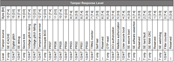
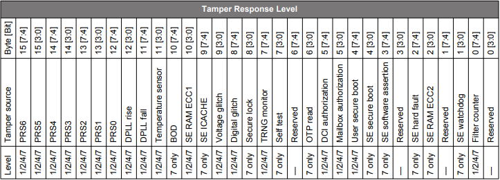
Anti-Tamper Configuration#
The 16 bytes of tamper response levels on HSE-SVH devices are described in the following tables.
Tamper Source Response Level on HSE-SVH (xG21B) Devices
Tamper Source Response Level on Other HSE-SVH Devices
Initialize Public Key#
This command is used to initialize the user public key(s) to the SE OTP. This is a one-time command.
Initialize Public Key Command
ID [31:16] | Option 1 [15:8] | Option 2 [7:0] | Command payload | Response payload |
|---|---|---|---|---|
0xFF07 | Key type, see following | 0x01 | See following | None |
Key type:
0x01 - Public Sign Key
0x02 - Public Command Key
Command payload - total 68 bytes:
Parity (the XOR of 32-bit words from item 2) - 4 bytes
Public key in option 1 - 64 bytes
Read Public Key#
This command can be used to read out one of the public keys that are permanently stored in SE OTP.
Read Public Key Command
ID [31:16] | Option 1 [15:8] | Option 2 [7:0] | Command payload | Response payload |
|---|---|---|---|---|
0xFF08 | Key type, see following | 0x01 | None | 64 bytes: public key in option 1 |
Key type:
0x01 - Public Sign Key
0x02 - Public Command Key
Initialize AES Key#
This command is used to initialize a 128-bit symmetric key to the SE OTP. This is a one-time command.
Note: This command is only available on HSE devices.
Initialize AES Key Command
ID [31:16] | Option 1 [15:8] | Option 2 [7:0] | Command payload | Response payload |
|---|---|---|---|---|
0xFF0B | Key type, see following | 0x01 | See following | None |
Key type:
0x05 - AES-128 key
Command payload - total 20 bytes:
Parity (the XOR of 32-bit words from item 2) - 4 bytes
Symmetric key in option 1 - 16 bytes
Set Debug Restrictions#
This command is used to set the restrictions for the debug port.
Set Debug Restrictions Command
ID [31:16] | Option 1 [15:8] | Option 2 [7:0] | Command payload | Response payload |
|---|---|---|---|---|
0x4312 | 0x00 | 0x00 | See following | None |
Command Payload – total 4 bytes. Debug restriction bit mask is defined in the table below.
Debug Port Restriction Bits
| Bit | Name | Description |
|---|---|---|
0 |
DBGLOCK |
Non-secure, invasive debug lock. |
1 |
NIDLOCK |
Non-secure, non-invasive debug lock. |
2 |
SPIDLOCK |
Secure, invasive debug lock. |
3 |
SPNIDLOCK |
Secure, non-invasive debug lock. |
Read Lock Status#
This command is used to read the lock status of the debug port.
Read Lock Status Command
ID [31:16] | Option 1 [15:8] | Option 2 [7:0] | Command payload | Response payload |
|---|---|---|---|---|
0x4311 | 0x00 | 0x00 | See following | None |
Debug port lock status – total 4 bytes:
Bit [0] - Debug lock (configuration status) is enabled if set
Bit [1] - Device erase enabled is enabled if set
Bit [2] – Secure debug lock enabled is enabled if set
Bit [3:4] – Reserved
Bit [5] – Debug lock hardware status is enabled if set
Bit [6] – Invasive debug lock is enabled if set
Bit [7] – Non-invasive debug lock is enabled if set
Bit [8] - Secure invasive debug lock is enabled if set
Bit [9] - Secure non-invasive debug lock is enabled if set