Gecko OS is now in maintenance and is not recommended for new designs. Please see the
Software Advisory
for detailed information (registration required).
AMW007 Spectre Module GPIOs and Peripherals
See also:
- Module details: AMW007
- Eval Board details: AMW007-E03
- Controlling GPIOs and Peripherals
- Device Memory
Functions and Pins
Medusa Evaluation Board
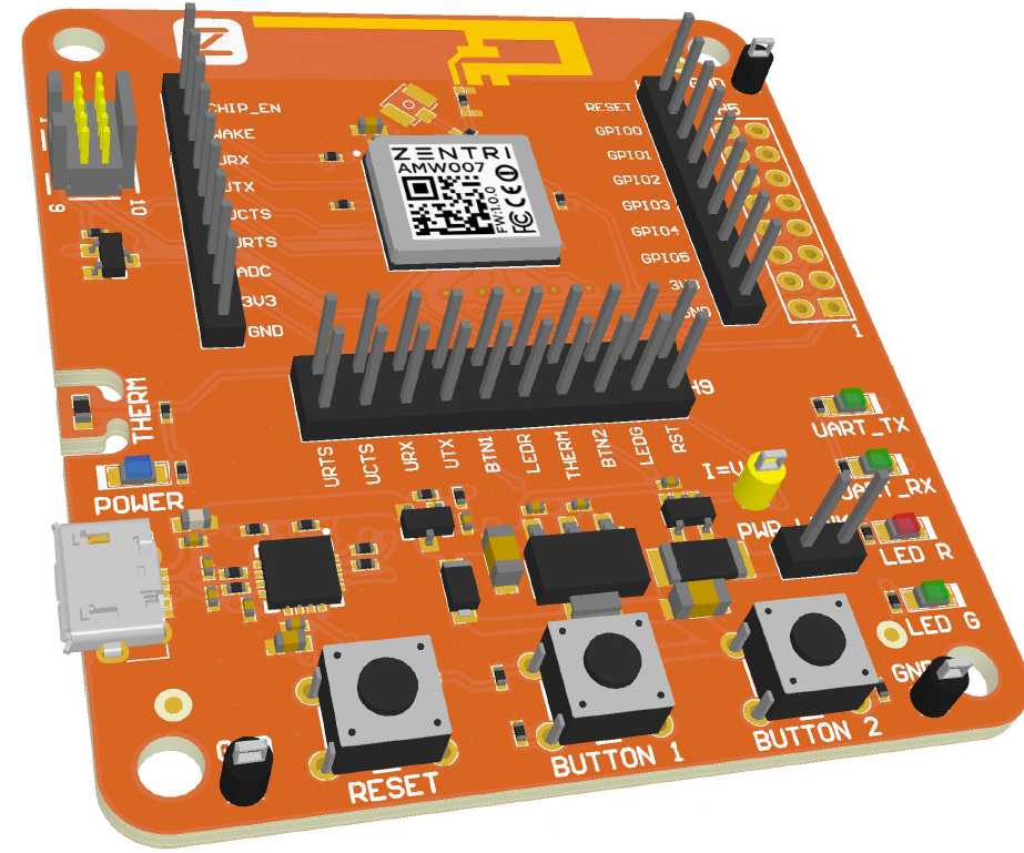
The table below shows functions, defaults and pins for the AMW007 Spectre GPIOs and other functions. The table also shows connections and header pins for the AMW007-E03 Medusa evaluation board.
| AMW007 Spectre | Medusa AMW007-E03 | E03.2 | ||||||
|---|---|---|---|---|---|---|---|---|
| GPIO | Functions | Default Function | Wake | Pad | Connections | Header-Pin | ||
| GPIO0 | Factory reset | Factory Reset | 5 | Button 1 | H2-2, H5-8, H9-2 | |||
| GPIO1 | none | 6 | LED_R - Red User LED | H2-3, H5-6, H9-9 | ||||
| GPIO2 | Boot control 1 | none | 9 | H2-4 | ||||
| GPIO3 | BOOT_SEL, Boot control 1 | none | 11 | H2-3 | ||||
| GPIO4 | none | 12 | LED_G - Green User LED | H2-6, H5-4, H9-3 | ||||
| GPIO5 | none | 21 | Button 2 | H2-7, H5-2, H9-5 | ||||
| GPIO6 | UART_CTS | none | 27 | H3-5, H5-7, H9-17 | ||||
| GPIO7 | UART_RTS | none | 28 | H3-6, H5-1, H9-19 | ||||
| wake | 3 | H3-2 | ||||||
| UART_RX | 7 | H3-3, H5-3, H9-15 | ||||||
| UART_TX, Boot control 1 | 8 | H3-4, H5-5, H9-13 | ||||||
| RESET_N | 26 | H9-1 | ||||||
| CHIP_EN | 34 | H3-1 | ||||||
| 35 | Thermistor | H3-7, H9-7 |
1 : The Boot control pins must be at the following levels immediately after a reset in order for the module to boot correctly: UART_TX = GND, GPIO2 = VDD, GPIO3 = VDD
Headers
- H2 - Expansion
- H3 - Expansion
- H5 - Peripheral
- H6 - Debug
- H9 - Isolation Jumpers - Note : Solder bridges on the bottom of the evaluation board short out the jumpers by default. Remove the bridges before using the H9 header.
Medusa reset pin
E03.2
- H2-1, H9-1
Medusa power header pins
E03.2
- GND: H2-9, H3-9, H5-9, H5-10, H5-13, H5-14
- VDD: H2-8, H3-8, H5-11, H5-12
Default Medusa GPIO Usage
The default Medusa GPIO usage shown in response to the command
get gpio.usage
is:
> get gp u

!  # Description
See the gpio.usage variable documentation.