Bus Level Security (BLS)#
System Design#
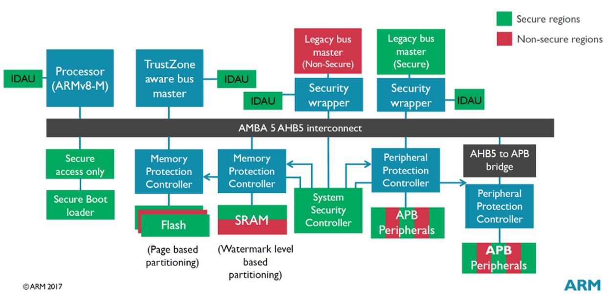
The following figure shows two system designs:
The sample system contains an ARMv8-M processor and the required components to support TrustZone.
Bus Level Security (BLS) on Series 2 devices implements the concepts introduced in the ARM TrustZone sample system. BLS enforces Secure and privileged programming models and uses security components (colored blocks) to configure the security attribute and privileged level of peripherals and Bus Masters.
ARMv8-M Processor#
The ARMv8M processor is TrustZone capable of Secure and Non-secure states. It has a dedicated internal SAU that is fully programmable up to 8 different memory regions. Out of reset, the processor is in a Secure state and every transaction is a Secure transaction.
ARMv8-M Processor in Series 2 devices is the Cortex-M33.
System Security Controller#
The system security controller is the central location for all security settings in the system. Each type of controller, IDAU, and wrapper receives its security configuration and bus response configuration from this block.
System Security Controller in Series 2 devices is the Security Management Unit (SMU).
Implementation Defined Attribution Unit (IDAU)#
The IDAU generates the security attribute for a given address. All IDAUs in the system have the same memory partitioning. The IDAU is intended only for ARMv8-M cores and utilizes the entire IDAU interface for the core. The lite IDAU uses only the Secure and Non-secure interface from the IDAU and is intended for Non-ARMv8-M Bus Masters.
IDAU in Series 2 devices is the External Secure Attribution Unit (ESAU).
Security Wrapper#
The Security Wrapper gives a legacy Bus Master the ability to drive security attribution. The security wrapper outputs the transaction address to the lite IDAU which returns the security attribute of the address. If the wrapper is configured as Non-secure, any transactions to a Secure address are blocked.
Security Wrapper in Series 2 devices is the Bus Master Protect Unit (BMPU).
Memory Protection Controller (MPC)#
MPC has a security configuration for a per block of memory or memory above and below the watermark. If the security attribute of the block or memory region does not match the security attribute of the address, the transaction is blocked. This controller is used in a system that alias RAM or flash memory locations. This controller is not needed when the memory region size is programmable in an IDAU.
Series 2 devices have a programmable flash and RAM region in the ESAU (equivalent to IDAU) and are not implementing this block.
Peripheral Protection Controller (PPC)#
PPC has a security configuration for every peripheral. If the security attribute of the selected peripheral does not match the security attribute of the address, the transaction is blocked. This controller is used in systems that alias the peripheral memory locations.
PPC in Series 2 devices is the Peripheral Protection Unit (PPU).
Hardware security is now extended to the peripheral bus system of the processor. Each component on the bus can verify and propagate the security level for each bus operation. The following sections describe the individual security component for BLS on Series 2 devices.
Security Management Unit (SMU)#
The SMU is the only user-facing block in the BLS architecture and houses all the configuration and status for the ESAUs, BMPUs, and PPUs.
Thirteen memory regions (ESAU)
Per Bus Master privileged and security attribute (BMPU)
Interrupt flag for Bus Master security fault (fault table in BMPU section)
Per peripheral privileged and security attribute (PPU)
Interrupt flags for privileged, security, and instruction peripheral access faults (fault tables in PPU section)
Separate Secure and Privileged IRQ
The SMU configurations can be locked down and protected from runaway code. The SMU_LOCK register resets to UNLOCK. Any write other than the unlock code (0xACCE55) locks all SMU registers from further updates. The SMU_STATUS register contains a SMULOCK bitfield with the current lock state of the SMU.
The SMU_M33CTRL register can lock down internal security and privileged configurations below.
Cortex-M33 SAU
Non-secure MPU
Secure MPU
Non-secure Vector Table Offset Register (VTOR)
Secure AIRCR register
Interrupt flags in the SMU_IF register can generate a Secure or Privileged interrupt in the table below when its corresponding interrupt enable bit in the SMU_IEN register is set and IRQn is enabled.
| Enable Bit in SMU_IEN Register | IRQn | Interrupt Handler |
|---|---|---|
BMPUSEC, PPUSEC | SMU_SECURE_IRQn | SMU_SECURE_IRQHandler() |
PPUPRIV, PPUINST | SMU_PRIVILEGED_IRQn | SMU_PRIVILEGED_IRQHandler() |
Each interrupt flag in the SMU_IF register can be cleared by writing 1 to the corresponding bit of the SMU_IF_CLR register.
External Secure Attribution Unit (ESAU)#
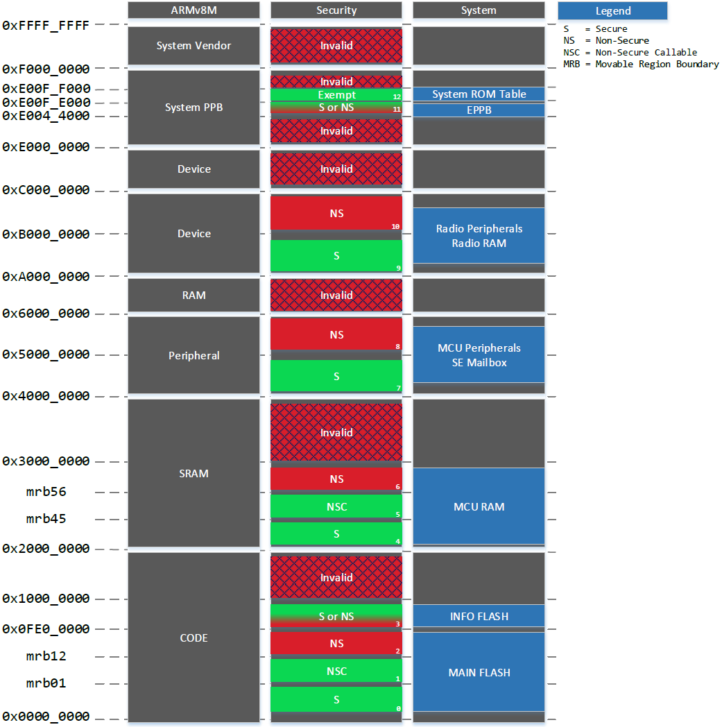
The ESAU is responsible for determining the memory region and security attribute of a given address. Referring to ARMv8-M TrustZone Implementation on page 16, the Cortex-M33 interfaces with an ESAU and the BMPUs of other Bus Masters interface with lite ESAUs to determine the security attribute of all transactions. The following figure describes the security attributes of different memory regions defined by the ESAU on Series 2 devices.
Notes:
For Series 2 devices with base address
0x08000000in region 0, the memory address from0x0to0x07FFFFFFis an invalid region.The invalid regions are deemed as Secure.
The NSC and Exempted attributes are only available to the ESAU, and all lite ESAUs in the system view these attributes as Secure.
The ESAU divides the memory map into 13 memory regions and has a maximum of 6 Non-secure regions.
Four Movable Region Boundaries (MRBs) determine the size of 6 regions.
Two regions have configurable security attributes.
Each memory region consists of a base address that specifies the start of the region and a limit address that specifies the end of the region plus one (+ 1).
The address is valid if it falls between the base (≥ base) and limit (< limit) of a region.
If the memory region is not defined, it is deemed invalid and Secure.
The MRBs distinguish the Secure, Non-secure Callable, and Non-secure regions in flash and RAM. The two configurable regions determine if the Info flash and Cortex-M33 EPPB regions are Secure or Non-secure. The MRBs have a specific programming sequence. Any misprogramming results in a SMUPRGERR in the SMU_STATUS register.
ARMv8-M CODE Regions#
Regions 0, 1, and 2 are in the Main space of flash. Region 3 is the info space of flash.
The mrb01 (
ESAUMRB01inSMU_ESAURMBR01register) determines the end of region 0 and the start of region 1.The mrb12 (
ESAUMRB12inSMU_ESAURMBR12register) determines the end of region 1 and the start of region 2.The size of region 3 is device-dependent.
Three regions' security attributes are static, and one region is configurable. Region 0 is always Secure, region 1 is always Non-secure Callable, and region 2 is always Non-secure. Region 3 is configurable as either Secure or Non-secure (
ESAUR3NSinSMU_ESAURTYPES0register, default is secure after reset).Sizes of regions 0, 1, and 2 are adjusted in 4 kB increments with the lower 12 bits of
ESAUMRB##inSMU_ESAURMBR##ignored.The Secure region can be set to size 0 when mbr01 = base address of region 0.
The Non-secure Callable regions can be set to size 0 when mbr01 = mbr12.
The default value of mbr01 is equal to base address +
0x02000000, so the size of region 0 is 32 MB. Out of reset, all flash is Secure since all Series 2 devices have less than 32 MB of flash.
| Region | Memory | Base Address | Limit Address | Security Attribute |
|---|---|---|---|---|
0 | Main flash | 0x00000000 or 0x08000000 | (0x00000000 or 0x08000000) | mbr01 | Secure |
1 | Main flash | (0x00000000 or 0x08000000) | mbr01 | (0x00000000 or 0x08000000) | mbr12 | Non-secure Callable |
2 | Main flash | (0x00000000 or 0x08000000) | mbr12 | 0x0FE00000 | Non-secure |
3 | Info flash | 0x0FE0000 | 0x10000000 | Secure or Non-secure |
ARMv8-M RAM Regions#
Regions 4, 5, and 6 cover the entire available RAM in the device.
The mrb45 (
ESAUMRB45inSMU_ESAURMBR45register) determines the end of region 4 and the start of region 5.The mrb56 (
ESAUMRB56inSMU_ESAURMBR56register) determines the end of region 5 and the start of region 6.All three regions' security attributes are static. Region 4 is always Secure, region 5 is always Non-secure Callable, and region 6 is always Non-secure.
Sizes of all three regions are adjusted in 4 kB increments with the lower 12 bits of
ESAUMRB##inSMU_ESAURMBR##ignored.The Secure region can be set to size 0 when mbr45 = base address of region 4.
The Non-secure Callable region can be set to size 0 when mbr45 = mbr56.
The default value of mbr45 is equal to
0x02000000, so the size of region 4 is 32 MB. Out of reset, all RAM is Secure since all Series 2 devices have less than 32 MB of RAM.
| Region | Memory | Base Address | Limit Address | Security Attribute |
|---|---|---|---|---|
4 | SRAM | 0x20000000 | 0x20000000 | mbr45 | Secure |
5 | SRAM | 0x20000000 | mbr45 | 0x20000000 | mbr56 | Non-secure Callable |
6 | SRAM | 0x20000000 | mbr56 | 0x30000000 | Non-secure |
ARMv8-M Peripheral Regions#
These regions are aliases to the chip peripherals and SE mailbox (a device with HSE).
Both regions have a fixed size.
Both regions' security attributes are static. Region 7 is always Secure, and region 8 is always Non-secure.
| Region | Memory | Base Address | Limit Address | Security Attribute |
|---|---|---|---|---|
7 | Chip Peripherals | 0x40000000 | 0x50000000 | Secure |
8 | Chip Peripherals | 0x50000000 | 0x60000000 | Non-secure |
ARMv8-M Device Regions#
These regions are aliases to all radio peripherals and radio RAM.
Both regions have a fixed size.
Both regions' security attributes are static. Region 9 is always Secure, and region 10 is always Non-secure.
From the perspective of the device bus system, the radio is one peripheral that is either Secure or Non-secure. So any Bus Master accessing the radio needs to know the security attribute of the radio. From the perspective of the radio, all of its radio bus peripherals are accessible regardless of the security attribute. However, the radio needs to know the security attribute of chip bus peripherals to access them through the correct alias.
| Region | Memory | Base Address | Limit Address | Security Attribute |
|---|---|---|---|---|
9 | Radio Peripherals | 0xA0000000 | 0xB0000000 | Secure |
10 | Radio Peripherals | 0xB0000000 | 0xC0000000 | Non-secure |
ARMv8-M System Private Peripheral Bus (PPB) Regions#
Both regions have a fixed size.
Region 11 is the Cortex-M33 EPPB memory region and is configurable as either Secure or Non-secure (
ESAUR11NSinSMU_ESAURTYPES1register, default is secure after reset). It is important to note that the Cortex-M33 core is the only Bus Master that sees these memory regions. All other Bus Masters in the system do not have access to the System PPB, and it is an invalid region.Region 12 has a static security attribute of Exempted. It means that the Cortex-M33 core allows the transaction in all cases. It permits debuggers to read the system ROM Table regardless of the state of the Cortex-M33 core.
| Region | Memory | Base Address | Limit Address | Security Attribute |
|---|---|---|---|---|
11 | EPPB | 0xE0044000 | 0xE00FE000 | Secure or Non-secure |
12 | System ROM Table | 0xE00FE000 | 0xE00FF000 | Exempted |
Notes:
The regions in flash (0/1/2) and RAM (4/5/6) can only create in the order of Secure, Non-secure Callable, and Non-secure.
The ESAU and lite ESAUs handle the transactions of Bus Masters and must have consistent security attribute mapping. Therefore, configurations in the SMU registers apply to ESAU and lite ESAUs.
Unlike other Bus Masters using BMPU and lite ESAU, merging the address lookup results from the internal SAU and ESAU determines the security attribute of the Cortex-M33 transaction.
| Bus Master | Security Attribution |
|---|---|
Cortex-M33 | SAU and ESAU |
Other | Lite ESAU |
Security Attribution Unit#
In Series 2 devices, the combination of the integrated SAU in the Cortex-M33 processor and an ESAU determine the security attribute of a Cortex-M33 transaction.
The SAU consists of several programmable registers. These registers are placed in the System Control Space (SCS) and are only accessible from the Secure privileged state.
SAU Control Register (
SAU_CTRL) — The SAU is disabled after RESETSAU Type Register (
SAU_TYPE) — Indicates the number of available regions (read-only)SAU Region Number Register (
SMU_RNR) — Assigns a region numberSAU Region Base Address Register (
SAU->RBAR) — Configures selected region base addressSAU Region Limit Address Register (
SAU->RLAR) — Configures selected region limit address and security attribute (NSC or NS), enable or disable the region
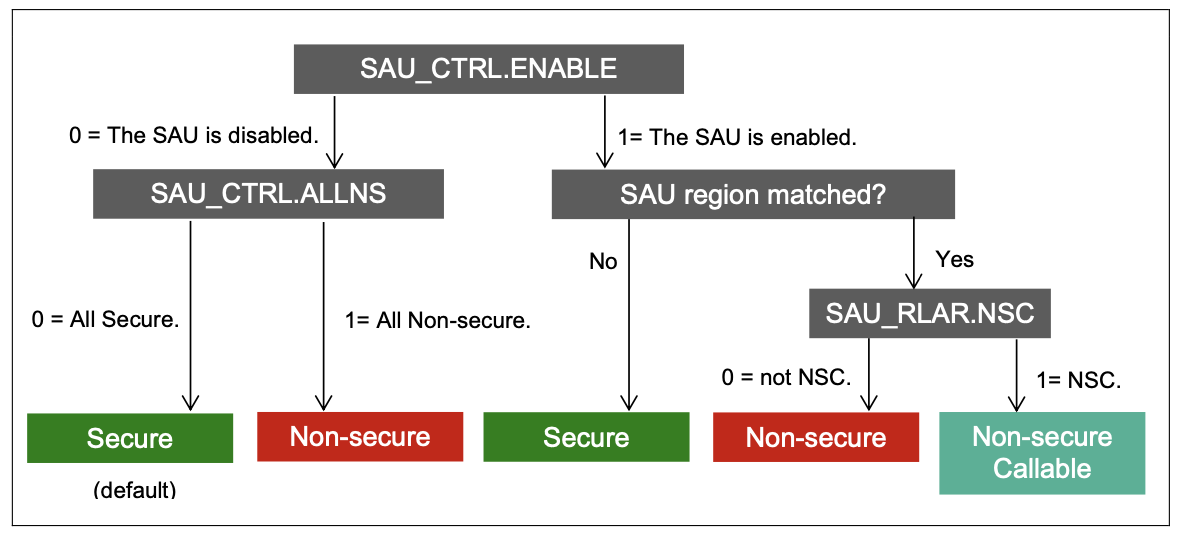
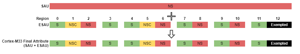
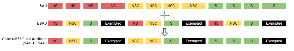
The following figure shows three different SAU configurations for determining the security attribute of a Cortex-M33 transaction.
Notes:
All address ranges after RESET in SAU are Secure by default.
The SAU can configure a 32 bytes aligned region as Non-secure or Non-secure Callable. Any address not defined in the SAU defaults to Secure.
An ESAU can configure or hard-code a region as Secure, Non-secure Callable, Non-secure, or Exempted. An Exempted region enables Non-secure debuggers to access debugging components and establish a debug connection to the processor before the SAU is configured.
The processor determines the final attribute of the address based on the higher security attribute (Exempted > S > NSC > NS) from either the SAU or the ESAU.

All Secure Configuration#
Highlights:
SAU is disabled.
ALLNSbit in the SAU Control register is clear.The whole memory is in a Secure state (highest security attribute apart from Exempted).
All Cortex-M33 transactions in this configuration are Secure or Exempted and give the Cortex-M33 access to all memory locations through either the Secure or Non-secure alias after RESET.
It is up to the boot procedure in a Secure state to keep the current configuration or use other configurations once the boot process is complete.
All Non-secure Configuration#
Highlights:
SAU is disabled.
ALLNSbit in the SAU Control register is set.The whole memory is in a Non-secure state (lowest security attribute).
Therefore the ESAU configuration determines the security attribute of all Cortex-M33 transactions.
Except for the
SAU_CTRLregister, this configuration does not require programming on other SAU registers.
Configurable Configuration#
Highlights:
SAU is enabled.
ALLNSbit in the SAU Control register can be 0 or 1 (do not care).The
NSCbit on theSAU_RLARregister determines the security attribute of an address as Non-secure or Non-secure Callable if an address matches an SAU region.The security attribute of an address is Secure by default if the address does not match any SAU region.
This configuration programs
SAU_RNR,SAU_RBAR, andSAU_RLARregisters to correlate the Non-secure regions in ESAU.The SAU or ESAU overrides the attribute to a higher security level if any security attribute mismatch occurs in a memory region.
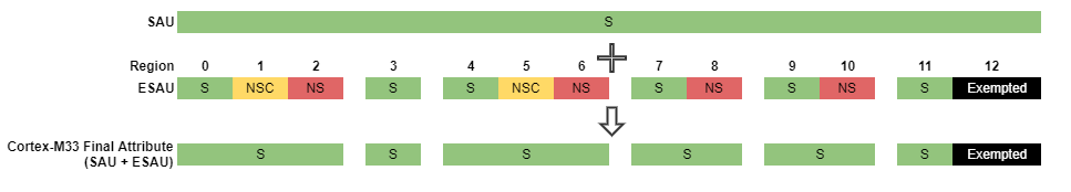
The following figure is an example of a configurable configuration with the size of ESAU regions 0 and 5 are set to zero.
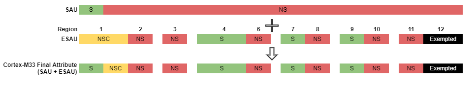
Note: The Cortex-M33 has an internal SAU that defaults all undefined addresses to Secure if enabled. If the Secure regions do not align between the Cortex-M33 (SAU + ESAU) and other Bus Masters (lite ESAU), the Cortex-M33 treats a memory region as Secure while other Bus Masters treat it as Non-secure. It can lead to the leaking of secure data if the Cortex-M33 stores secure data in what other Bus Masters think is a Non-secure area (Main Flash Layout on page 34).
Bus Master Protection Unit (BMPU)#
The BMPU is a security wrapper used for assigning a Bus Master specific security and privileged states. Referring to Figure 3.1 ARMv8-M TrustZone Implementation on page 16, the BMPU generally lies between the Bus Master and the Advanced High-performance Bus (AHB) Matrix. BMPU interfaces with a lite ESAU to determine the security attribute of all Bus Master transactions.
The registers below in SMU configure the security and privileged state of a Bus Master. The Bus Masters in group 0 are device-dependent. Out of reset, each Bus Master is Secure and privileged.
| Register | Description |
|---|---|
SMU_BMPUPATD0 | Bitfields (privileged if set) for privileged attribute configuration on Bus Master group 0 |
SMU_BMPUSATD0 | Bitfields (Secure if set) for security attribute configuration on Bus Master group 0 |
Note: The Bus Master privileged attribute only applies to peripheral accesses. Flash and RAM accesses ignore the privileged attribute of the Bus Master.
The BMPU generates a security fault when the security attribute of the bus transaction is Secure, and the security attribute (SMU_BMPUSATD0) for the BMPU is configured as Non-secure.
Below is the security fault table that shows how the security attribute on the bus is driven based on the lite ESAU attribute and the BMPU security configuration. The interrupt is triggered if BMPUSEC in SMU_IEN is set and the SMU_SECURE_IRQn is enabled.
| Lite ESAU Attribute | Secure Bus Master | Non-secure Bus Master |
|---|---|---|
Non-secure | Non-secure | Non-secure |
Secure | Secure | FAULT |
Upon a BMPU fault, the registers in SMU below notify that a BMPU security fault occurred and on which Bus Master. The registers also identify the offending fault address. If a fault is detected, the response is Read As Zero (RAZ) or Write Ignored (WI) and the corresponding interrupt flag is set in the SMU_IF register. The values in SMU_BMPUFS and SMU_BMPUFSADDR do not change until the BMPU fault (BMPUSEC) in the SMU_IF register is cleared by software.
| Register | Bitfield | Fault |
|---|---|---|
SMU_IF | BMPUSEC | Security Fault if set |
SMU_BMPUFS | BMPUFSMASTERID | ID of the Bus Master that triggered the fault |
SMU_BMPUFSADDR | BMPUFSADDR | Access address that triggered the fault |
Note: No privileged fault is generated because all the other Bus Masters in the system do not drive the privileged attribute.
Peripheral Protection Unit (PPU)#
The PPU is a security wrapper used for assigning a Bus Slave peripheral specific security and privileged states. Referring to Figure 3.1 ARMv8-M TrustZone Implementation on page 16, the PPU comes in the form of a PPU in Advanced High-performance Bus (AHB) and a PPU in Advanced Peripheral Bus (APB).
The PPU AHB generally lies between the Bus Matrix and an AHB Bus Slave peripheral.
The PPU APB lies between the output of an AHB to APB bridge and all of the APB Slaves on that APB bus.
The registers below in SMU configure the security and privileged state of a peripheral. The peripherals in groups 0 and 1 are device-dependent. Out of reset, each peripheral is Secure and privileged. While each peripheral in address 0x40000000 (region 7) or 0x50000000 (region 8) can be configured independently, the radio subsystem in 0xA0000000 (region 9) or 0xB0000000 (region 10) is configured as a unit.
| Register | Description |
|---|---|
| SMU_PPUPATD0 | Bitfields (privileged if set) for privileged access configuration on peripheral group 0 |
| SMU_PPUPATD1 | Bitfields (privileged if set) for privileged access configuration on peripheral group 0 |
| SMU_PPUSATD0 | Bitfields (Secure if set) for security access configuration on peripheral group 0 |
| SMU_PPUSATD1 | Bitfields (Secure if set) for security access configuration on peripheral group 1 |
The PPU can generate three types of faults:
Privileged faults occur on unprivileged transactions to privileged peripherals. Below is the privileged fault table that shows when a privileged fault occurs based on the PPU peripheral privileged configuration and the bus transaction privileged attribute. The interrupt is triggered if
PPUPRIVinSMU_IENis set and theSMU_PRIVILEGED_IRQnis enabled.Bus Attribute Privileged Peripheral Unprivileged Peripheral Privileged
SUCCESS
SUCCESS
Unprivileged
FAULT
SUCCESS
Security faults occur on Secure transactions to Non-secure peripherals and Non-secure transactions to Secure peripherals. Below is the security fault table that shows when a security fault occurs based on the PPU Peripheral security configuration and the bus transaction security attribute. The interrupt is triggered if
PPUSECinSMU_IENis set and theSMU_SECURE_IRQnis enabled.Bus Attribute Secure Peripheral Non-secure Peripheral Secure
SUCCESS
FAULT
Non-secure
FAULT
SUCCESS
Instruction faults occur on any transaction marked as an instruction fetch. Below is the instruction fault table that shows when a PPU instruction fault occurs based on the bus transaction instruction attribute. The interrupt is triggered if
PPUINSTinSMU_IENis set and theSMU_PRIVILEGED_IRQnis enabled.Bus Attribute Secure Peripheral Non-secure Peripheral Secure
SUCCESS
FAULT
Non-secure
FAULT
SUCCESS
Upon a PPU fault, the registers below in SMU notifies which PPU fault occurred and on which peripheral. If a fault is detected, the response is Read As Zero (RAZ) or Write Ignored (WI) and set the corresponding interrupt flag in the SMU_IF register. The values in SMU_IF and SMU_PPUFS do not change until all PPU faults in the SMU_IF register are cleared by software.
| Register | Bitfield | Fault |
|---|---|---|
SMU_IF | PPUPRIV | Privilege Fault if set |
SMU_IF | PPUSEC | Security Fault if set |
SMU_IF | PPUINST | Instruction Fault if set |
SMU_PPUFS | PPUFSPERIPHID | ID of the peripheral that caused the fault |
Compatibility#
Secure software usually controls the SYSCFG and SMU peripherals to prevent Non-secure software from changing critical configurations in the Secure domain. It requires switching between Secure and Non-secure states when Non-secure software wants to update the registers in these peripherals. Therefore dedicated registers for Non-secure access are added to SYSCFG and SMU peripherals on newer Series 2 devices.
System Configuration (SYSCFG)#
Except for EFR32xG21 devices, the following tables apply to all Series 2 devices.
Table: Dedicated Bitfield to Configure Access for Non-secure SYSCFG Registers
| Bitfield (Register) | Description |
|---|---|
SYSCFGCFGNS (SMU_PPUPATD0) | Bitfields (privileged if set) for privileged access configuration on NS SYSCFG registers |
SYSCFGCFGNS (SMU_PPUSATD0) | Bitfields (Secure if set) for security access configuration on NS SYSCFG registers |
Note: Reset
SYSCFGCFGNSbit inSMU_PPUSATD0to allow Non-secure software to access NS SYSCFG registers.
Table: Dedicated SYSCFG Registers for Non-secure State
| SYSCFG Non-secure Registers | Description |
|---|---|
SYSCFG_CFGNS_CFGNSTCALIB | NS SysTick calibration value register |
SYSCFG_CFGNS_ROOTNSDATA0 | NS root data register 0 |
SYSCFG_CFGNS_ROOTNSDATA0 | NS root data register 1 |
Security Management Unit (SMU)#
Except for EFR32xG21 devices, the following tables apply to all Series 2 devices.
Table: Dedicated Bitfield to Configure Access for Non-secure SMU Registers
| Bitfield (Register) | Description |
|---|---|
SMUCFGNS (SMU_PPUPATD1) | Bitfields (privileged if set) for privileged access configuration on NS SMU registers |
SMUCFGNS (SMU_PPUSATD1) | Bitfields (Secure if set) for security access configuration on NS registers |
Note: Reset
SMUCFGNSbit inSMU_PPUSATD1to allow Non-secure software to access NS SMU registers.
The SMU_CFGNS register file is for the TrustZone Non-secure state and has its register lock (NSLOCK). It allows hardware to maintain the privileged assignments for the NS state. The privileged configuration within the NS state is the same as the Secure state, except it has an "NS" to differentiate the registers.
Table: Dedicated SMU Registers for Non-secure State
| SMU Non-secure Registers | Description |
|---|---|
SMU_CFGNS_NSSTATUS | Lock status of SMU_CFGNS registers |
SMU_CFGNS_NSLCOK | Lock and unlock the SMU_CFGNS registers |
SMU_CFGNS_NSIF | Interrupt flags for NS privilege (PPUNSPRIVIF) and instruction (PPUNSINSTIF) faults |
SMU_CFGNS_NSIEN | Interrupt enable flags for NS privilege (PPUNSPRIVIEN) and instruction (PPUNSINSTIEN) faults |
SMU_CFGNS_PPUNSPATD0 | Bitfields (privileged if set) for NS privileged access configuration on peripheral group 0 |
SMU_CFGNS_PPUNSPATD1 | Bitfields (privileged if set) for NS privileged access configuration on peripheral group 1 |
SMU_CFGNS_PPUNSFS | ID (PPUFSPERIPHID) of the NS peripheral that caused the fault |
SMU_CFGNS_BMPUNSPATD0 | Bitfields (privileged if set) for privileged attribute configuration on NS Bus Master group 0 |
Table: Fault Statuses Only for Secure State
| Bitfield (Register) | Description |
|---|---|
PPUPRIV (SMU_IF) | Fault status now limited only to Secure state |
PPUINST (SMU_IF) | Fault status now limited only to Secure state |
PPUPRIV (SMU_IEN) | Fault status now limited only to Secure state |
PPUINST (SMU_IEN) | Fault status now limited only to Secure state |
PPUFSPERIPHID (SMU_PPUFS) | Fault status now limited only to Secure state |
Table Dedicated SMU Interrupt for Non-secure State
| Interrupt | Description |
|---|---|
SMU_NS_PRIVILEGED_IRQHandler() | An interrupt flag in the SMU_CFGNS_NSIF register can generate an NS privileged interrupt when its corresponding interrupt enable bit in the SMU_CFGNS_NSIEN register is set and SMU_NS_PRIVILEGED_IRQn is enabled, and in which the peripheral (ID) that triggers the fault is in the SMU_CFGNS_PPUNSFS register. |