Secure Boot Process#
Introduction#
Secure Boot is a foundational component of platform security, as the absence of it can allow malicious code to subvert protections like secure storage, secure data transport, secure identity, and data confidentiality.
Secure Boot works as a process by which each piece of firmware is validated for authenticity and integrity before it is allowed to run. Each authenticated module can also validate additional modules before executing them, forming a chain of trust. If any module fails its security check, it is not allowed to run, and program control will typically stall in the validating module. In most lightweight IoT systems, the behavior of a Secure Boot failure is to cause the device to stop working until an authentically signed image can be loaded onto it. Whereas this may seem extreme, it is a better outcome than a smart light bulb being repurposed to mine crypto-currency, or a smart speaker being repurposed as a surveillance device on the end user’s private conversations.
The first link in the chain of trust is the root of trust. This is often the weakest link in the Secure Boot chain because the root of trust itself is not checked for authenticity or integrity. The security strength of the root of trust lies in its immutability. The strongest roots of trust have their firmware origin in ROM and use a Public Sign Key that is also located in ROM.
Series 1, Series 2, and Series 3 devices use a two-stage boot design consisting of a non-upgradable first stage root of trust followed by an upgradable second stage. In Series 1 devices, the root of trust (also called the first-stage bootloader) is in flash rather than ROM, and the upgradable portion (the main bootloader) is checked for integrity using a CRC32 checksum but is not checked for authenticity using a Public Sign Key. In Series 2 and Series 3 devices, the root of trust is in ROM, and the upgradable portion is checked both for integrity and authenticity.
The Secure Boot with RTSL is implemented by Root code executed by the Hardware Secure Engine (HSE) or the Cortex-M33 operating in Root Mode (VSE). For more information about SE, see section Secure Engine Subsystem in Series 2 and Series 3 Secure Debug.
In Series 3 devices, once firmware is programmed to the device, the code regions must be closed. Closing a code region locks it to prevent writes, as well as further configuration, and indicates to the SE that it can now be accessed by the SE. After flashing the firmware image, commander automatically closes the code region. To open a closed code region, an erase must be performed. If a code region is not closed, the SE will return a fault when attempting to access the open code region during secure boot verification of the host firmware. Each time a code region is closed, the SE's MTP (Multiple Times Programmable) memory section is updated, which causes an SE OTP bit to be used. More details on SE OTP bits is covered in the following section.
Silicon Labs provides Custom Part Manufacturing Service (CPMS) to customize the users' security features and settings. This application note uses the following abbreviations:
FSB: First Stage Bootloader
SSB: Second Stage Bootloader
GBL: Gecko Bootloader
RTSL: Root of Trust and Secure Loader
HSM: Hardware Security Module
OTP: One-Time Programmable
WSTK: Wireless Starter Kit
GSDK: Gecko Software Development Kit. For more information, refer to GSDK
SiSDK: Simplicity Software Development Kit. For more information, refer to SiSDK
ECDSA-P256-SHA256: Elliptic Curve Digital Signature Algorithm aka ECDSA using a P-256 curve and a SHA256 hash
PEM (.pem): Privacy Enhanced Mail
DER (.der): Distinguished Encoding Rules
ECDSA-P256-SHA256 Secure Boot in Series 1 Devices#
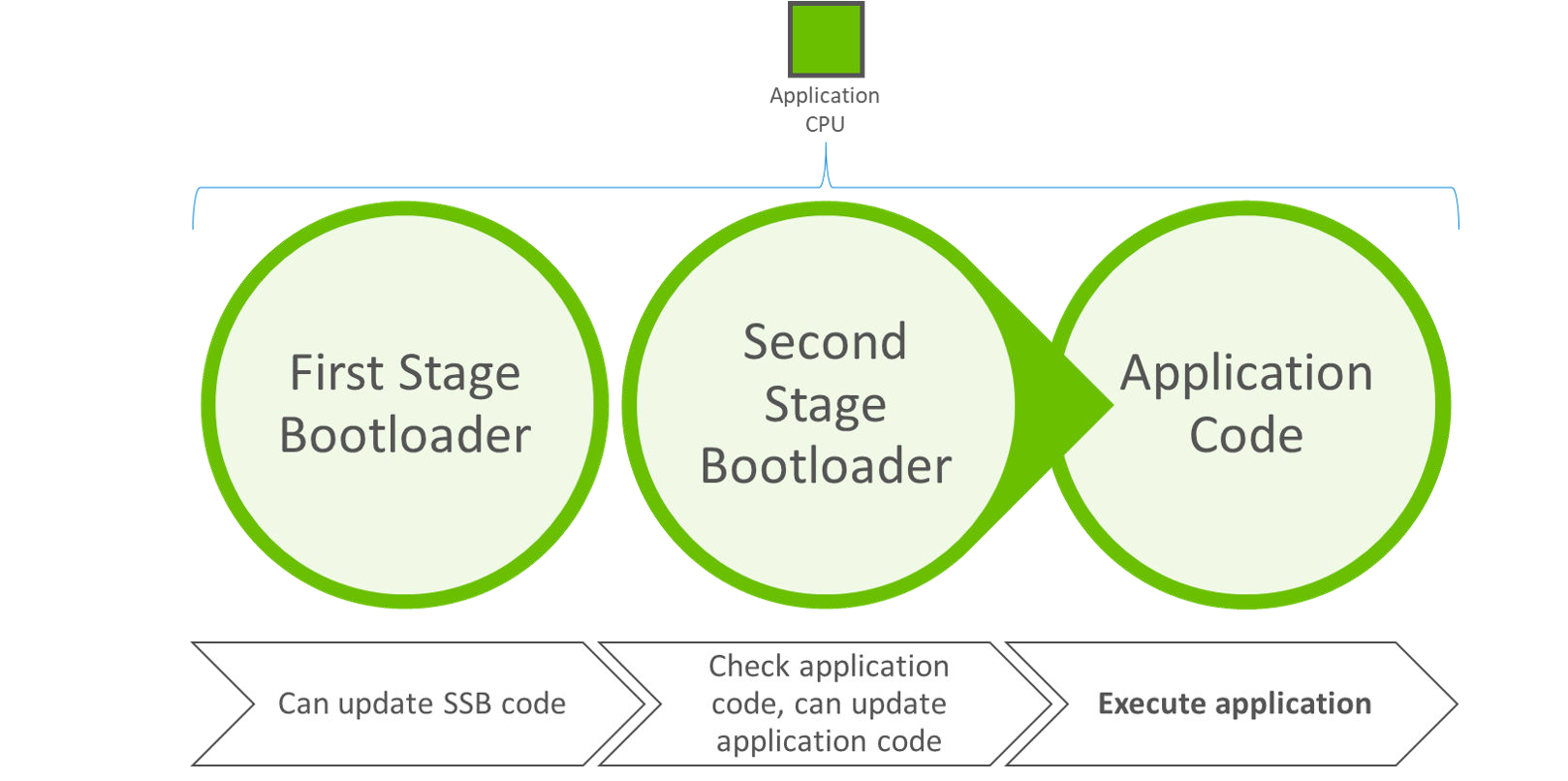
The Secure Boot process for Series 1 (SVB) devices originates in flash, typically with the execution of the first stage of GBL. The first stage of GBL checks to see if an upgrade is pending for the second stage of GBL. If so, it processes the upgrade of the second stage and then executes it. Otherwise, it just executes the second stage. If Secure Boot is enabled, the second stage of GBL checks the integrity and authenticity of the application image before executing it. If the integrity check fails, program control remains in the SSB. The following figure illustrates the Secure Boot process on Series 1 devices.
See UG266/Silicon Labs Gecko Bootloader User’s Guide for Series 3 and Higher for more information to generate and download signed firmware images using Simplicity Commander.
ECDSA-P256-SHA256 Secure Boot in Series 2 and Series 3 Devices#
For Series 2 and Series 3 devices, the Secure Engine (SE) implements the FSB to authenticate and upgrade the SSB. The GBL implements the SSB (aka Main Bootloader in UG266/Silicon Labs Gecko Bootloader User’s Guide for Series 3 and Higher) to authenticate and upgrade the application firmware.
Refer to the Gecko Bootloader Security Features section in UG266/UG489 and ECDSA-P256-SHA256 Secure Boot example for more information about the ECDSA-P256-SHA256 secure boot process in Series 2 devices and Series 3.
Note: It is possible to have a 2-stage design to skip the SSB between FSB and application. However, the application cannot be upgraded if discarding the SSB, and this application note assumes the SSB is present.
HSE#
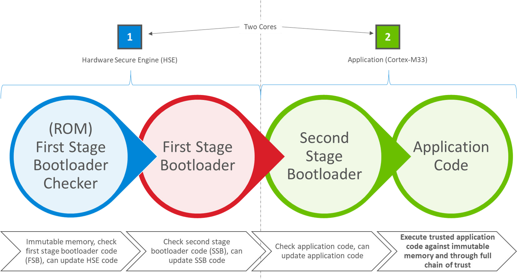
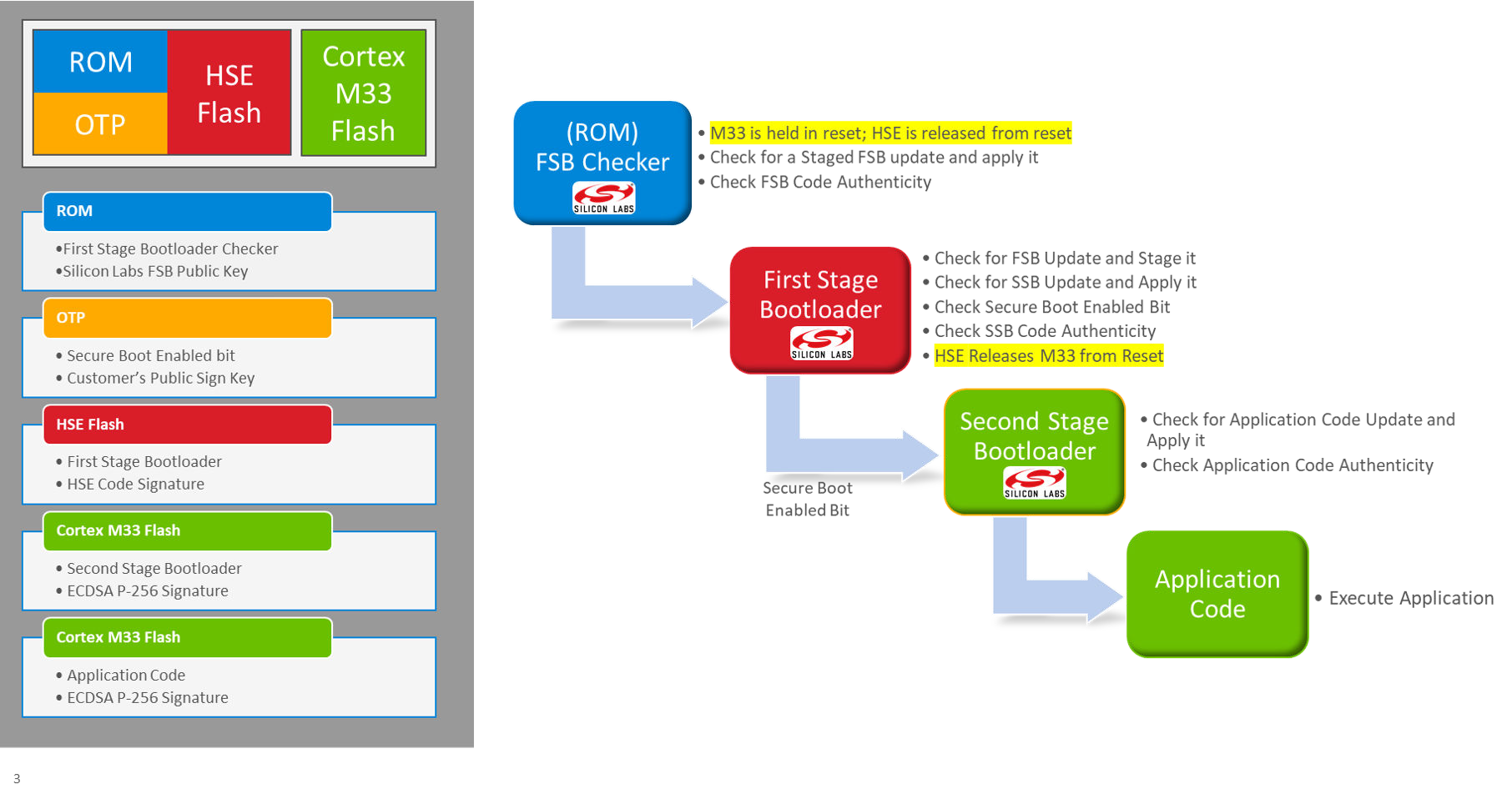
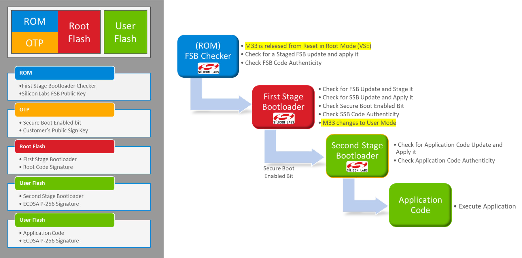
In HSE-SVM, HSE-SVH, and Series 3 Secure Vault devices, the Secure Boot process originates in ROM contained in the security co-processor (HSE). The following figures illustrate the Secure Boot process and flow on Series 2 HSE and Series 3 devices.
VSE#
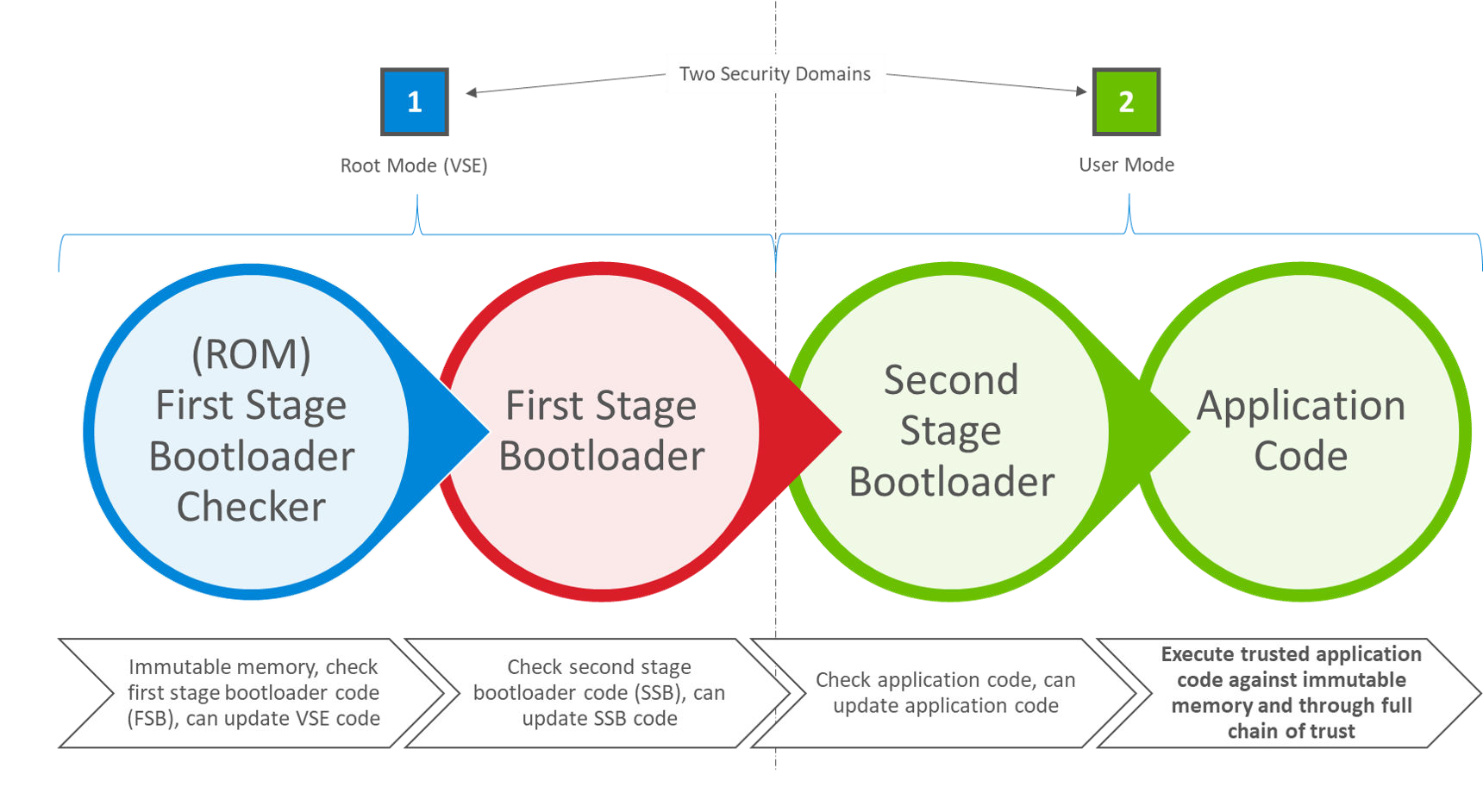
In VSE-SVM devices, the host MCU (Cortex-M33) assumes an elevated security state out of reset and securely boots itself from code that originates in ROM. The following figures illustrate the Secure Boot process and flow on Series 2 VSE devices.
Certificate-based Secure Boot in Series 2 and Series 3 Devices#
Refer to the Gecko Bootloader Security Features section in UG266: Silicon Labs Gecko Bootloader User’s Guide for GSDK 3.2 and Lower/Silicon Labs Gecko Bootloader User's Guide for GSDK 4.0 and Higher (series 1 and 2 devices) and Certificate-Based Secure Boot example for details about the certificate-based Secure Boot process in Series 2 and Series 3 devices.
The certificate-based Secure Boot process uses key delegation to minimize the exposure of the Private Sign Key, thereby reducing the likelihood that the corresponding Public Sign Key would need to be revoked.
If the certificate’s private key is leaked, all devices that have been programmed with that certificate are at risk until they can be updated with an image containing a certificate with a [higher version](./03-examples.md#certificate-revocation(03-examples.md#certificate-revocation).
Secure Loader#
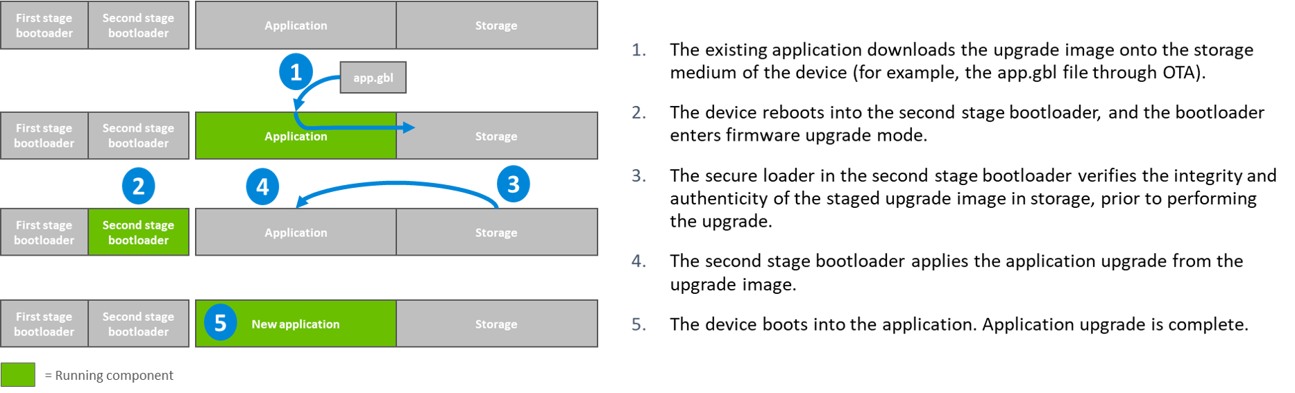
In Series 2 and Series 3 devices, the Secure Loader is firmware pre-loaded into the chip. Silicon Labs maintains the Secure Loader and deploys through secure upgrade packages. It is the functional equivalent of the first-stage GBL on Series 1 devices (refer to UG266: Silicon Labs Gecko Bootloader User’s Guide for GSDK 3.2 and Lower/Silicon Labs Gecko Bootloader User's Guide for GSDK 4.0 and Higher (series 1 and 2 devices) for more information). The Secure Loader validates the authenticity and integrity of a staged image before performing an upgrade operation. The Secure Loader requires the staged image to reside on-chip and the staged image must not overlap with the target destination address range. Firmware images that originate from off-chip, either off-chip storage, external NCP/ RCP host interface, or through an OTA update procedure are expected to be staged either by the application or by SSB before calling the Secure Loader to perform the upgrade.
Secure Boot Time#
Secure boot extends the recovery time from all sources of device reset. The duration of each authentication operation depends on the factors below:
Computation of the SHA-256 digest (32 bytes) of the associated image, which is proportional to the size of the firmware image.
Verification of the ECDSA-P256 signature of the SHA-256 digest above, which is independent of image size.
The clock frequency of the Crypto Engine, which is the HSE or CRYPTOACC in VSE devices.
Authentication | Enable/Disable | Duration |
|---|---|---|
FSB code | Enable (cannot disable) | FSB code size dependent |
SSB code | Disable (by default) | SSB code size and SE firmware version dependent |
Application code | Disable (by default) | Application code size and SSB firmware (GBL) version dependent |
Notes:
It will extend the boot time for certificates authentication if using Certificate-Based Secure Boot.
Refer to device-specific datasheets (like EFR32MG21B) for data about the boot timing of Series 2 devices.
Refer to Secure Boot Configuration below on how to enable the SSB and application code authentication.
Secure Boot Configuration#
The following sections describe how to configure the Secure Boot of the SSB (GBL) and application firmware.
SSB#
In Series 2 and Series 3 devices, the immutable OTP memory stores the Public Sign Key, Secure Boot Enable flag, and Anti-rollback flag. The user cannot change its respective value once either is programmed. Once the Public Sign Key is provisioned, it remains provisioned to that key value for the life of the device. Once Secure Boot and Anti-rollback is enabled, it remains enabled for the life of the device. Both of these assignment operations are IRREVOCABLE.
The Public Sign Key used for Series 2 and Series 3 devices is the public portion of an ECDSA key pair over the NIST prime curve P-256. The Public Sign Key is a customer key and is typically provisioned during the initial product manufacturing and device programming phase. It is common for all products that share the same firmware image to be loaded with the same Public Sign Key. The key loaded into the device is a public key and has no confidentiality requirements. The private key associated with that public key, which will be used to sign firmware images or certificates, should be tightly held, ideally secured in the HSM or equivalent key storage instrument.
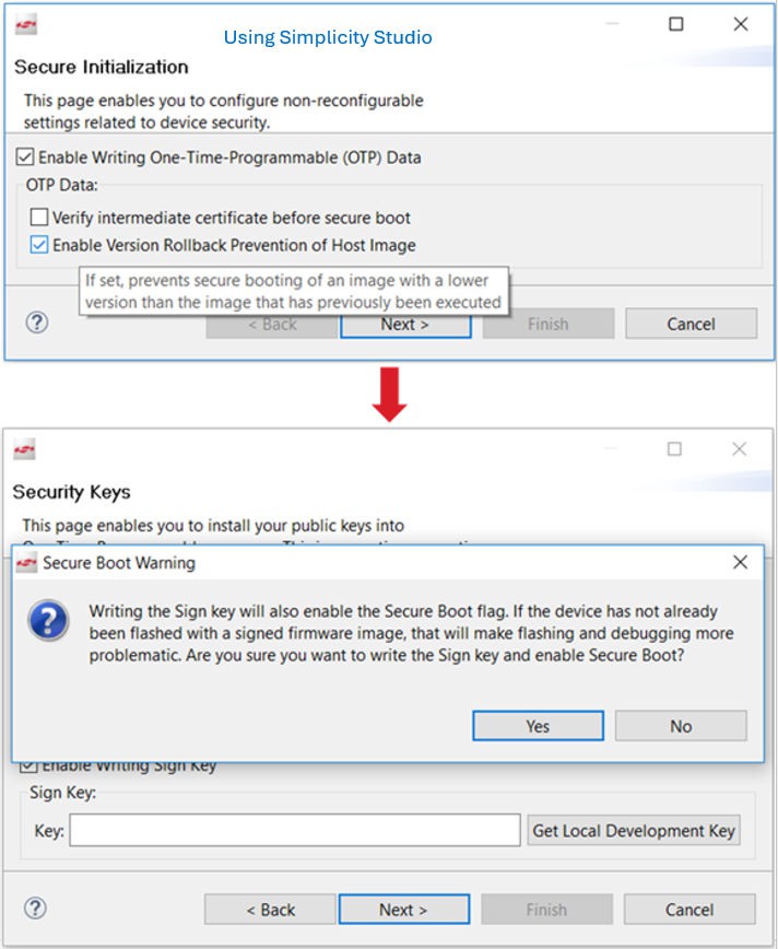
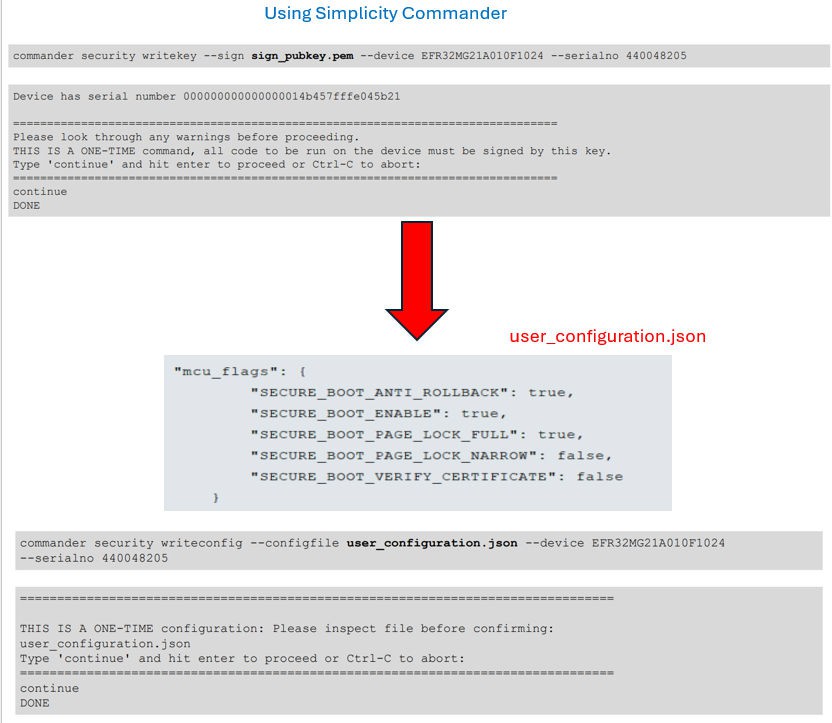
You can use Simplicity Commander, SE Manager, or Simplicity Studio to program the Public Sign Key and configure the SSB Secure Boot with anti-rollback in SE OTP. The following figures show the Simplicity Studio and Simplicity Commander implementation, for detailed steps refer to the Example section:
Application Firmware#
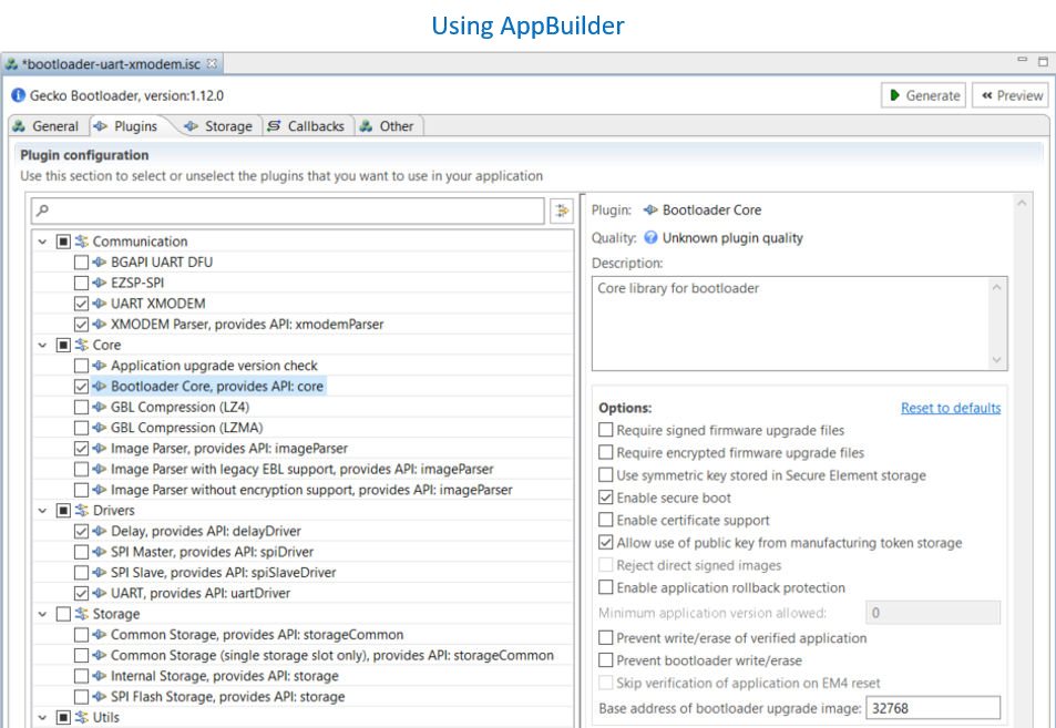
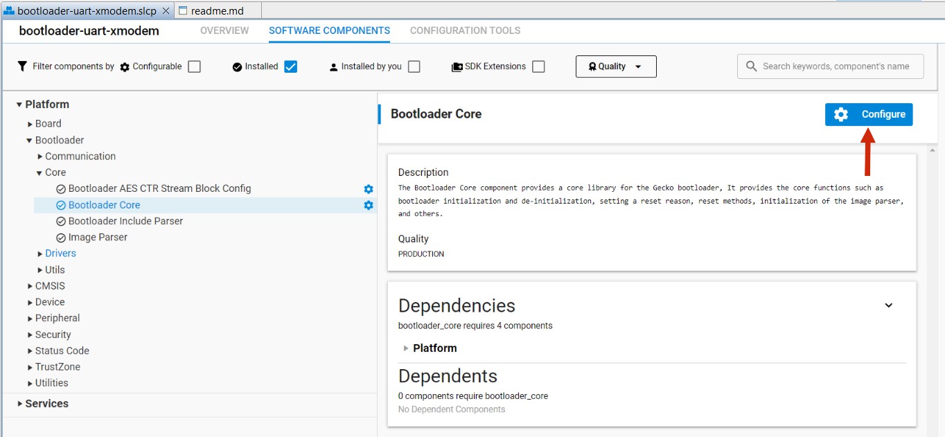
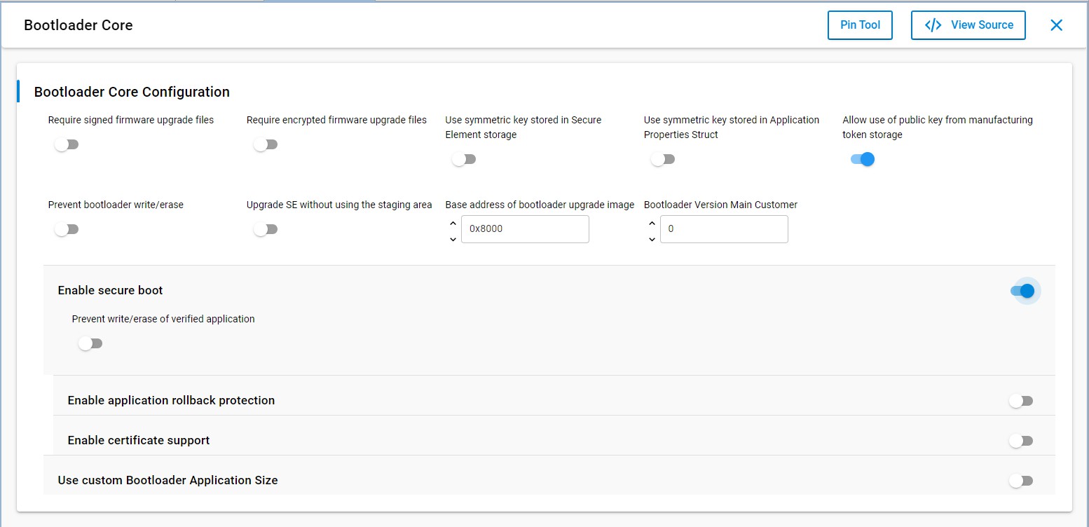
You can use the AppBuilder or Bootloader-core software component in the GBL project to configure the security options of the application firmware.
You can reconfigure the Secure Boot configuration of the application firmware by upgrading the GBL with the new custom settings.
Using Bootloader core compoent
Note: Install "Bootloader Core (Series-3)" for series 3 devices.