USB Device Classes#
The USB classes available in Micrium OS USB Device share some common characteristics. This section explains these characteristics and their interactions with the core layer.
About Class Instances#
The USB classes available in USB Device implement the concept of class instances. A class instance represents one function within a device. The function can be described by one interface or by a group of interfaces and belongs to a specific class.
Each USB class implementation has some configurations and functions in common, based on the concept of class instance. The common configurations and functions are presented in Table - Constants and Functions Related to the Concept of Multiple Class Instances in the USB Device Classes page. In the column title 'Constants or Function', the placeholder XXXX can be replaced by the name of the class: CDC, HID, MSC, CDC_EEM or VENDOR (Vendor for function names).
Table - Constants and Functions Related to the Concept of Multiple Class Instances
Constant or Function | Description |
|---|---|
.ClassInstanceQty (in structure USBD_XXXX_QTY_CFG) | Configures the maximum number of class instances. |
.ConfigQty (in structure USBD_XXXX_QTY_CFG) | Configures the maximum number of configurations per device. During the class initialization, a created class instance will be added to one or more configurations. |
USBD_XXXX_Add() | Creates a new class instance. |
USBD_XXXX_CfgAdd() | Adds an existing class instance to the specified device configuration. |
In terms of code implementation, the class will declare a local global table that contains a class control structure. The size of the table is determined by the constant USBD_XXXX_CFG_MAX_NBR_DEV. This class control structure is associated with one class instance and will contain specific information to manage the class instance.
The following illustrations present several case scenarios. Each illustration includes a code listing that corresponds to the case scenario.
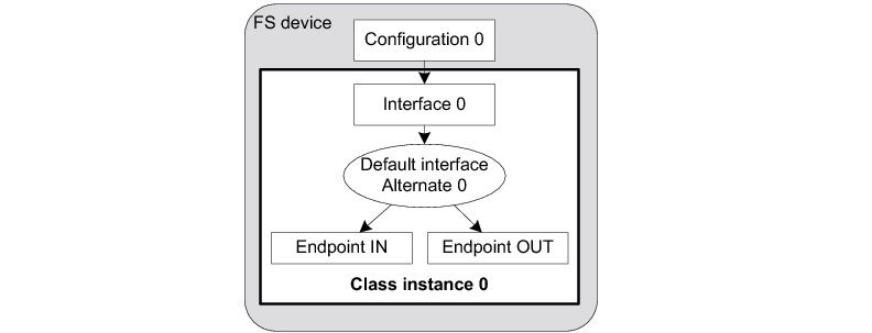
Figure 1 Multiple Class Instances - FS Device (1 Configuration with 1 Interface) in the USB Device Classes page represents a typical USB device. The device is Full-Speed (FS) and contains a single configuration. The function of the device is described by one interface composed of a pair of endpoints for data communication. One class instance is created, and it will allow you to manage the entire interface with its associated endpoint.
Figure - Multiple Class Instances - FS Device (1 Configuration with 1 Interface)#
The code corresponding to Figure 1 Multiple Class Instances - FS Device (1 Configuration with 1 Interface) in the USB Device Classes page is shown in Listing - Multiple Class Instances - FS Device (1 Configuration with 1 Interface) in the USB Device Classes page.
Listing - Multiple Class Instances - FS Device (1 Configuration with 1 Interface)#
RTOS_ERR err;
CPU_INT08U class_0;
USBD_XXXX_QTY_CFG qty_cfg;
qty_cfg.ClassInstanceQty = 1u;
qty_cfg.ConfigQty = 1u;
USBD_XXXX_Init(&qty_cfg, &err); (1)
if (err.Code != RTOS_ERR_NONE) {
/* $$$$ Handle the error. */
}
class_0 = USBD_XXXX_Add(&err); (2)
if (err.Code != RTOS_ERR_NONE) {
/* $$$$ Handle the error. */
}
USBD_XXXX_ConfigAdd(class_0, dev_nbr, config_0, &err); (3)
if (err.Code != RTOS_ERR_NONE) {
/* $$$$ Handle the error. */
}(1) Initialize the class. All internal variables, structures, and class ports will be initialized. Note that the Init() function in some classes may take other arguments.
(2) Create the class instance, which is class_0. The function USBD_XXXX_Add() allocates a class control structure associated with class_0. Depending on the class, USBD_XXXX_Add() may have additional parameters aside from the error code that represent class-specific information stored in the class control structure.
(3) Add the class instance, class_0, to the specified configuration number, config_0, on the device referenced by dev_nbr. USBD_XXXX_ConfigAdd() will create the interface 0 and its associated IN and OUT endpoints. As a result, the class instance encompasses the interface 0 and its endpoints. Any communication done on the interface 0 will use the class instance number, class_0.
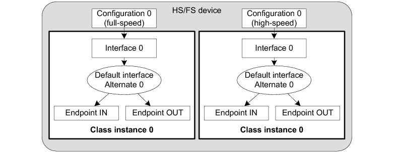
Figure - Multiple Class Instances - HS/FS Device (2 Configurations and 1 Single Interface) in the USB Device Classes page represents an example of a high-speed capable device. The device can support High-Speed (HS) and Full-Speed (FS). The device will contain two configurations:
One valid if the device operates at full-speed
Another if it operates at high-speed
In each configuration, interface 0 is the same, but its associated endpoints are different. The difference will be the endpoint maximum packet size, which varies according to the speed. If a high-speed host enumerates this device, then by default, the device will work in high-speed mode and therefore the high-speed configuration will be active. The host can learn about the full-speed capabilities by getting a Device_Qualifier descriptor followed by an Other_Speed_Configuration descriptor. These two descriptors describe a configuration of a high-speed capable device if it were operating at its other possible speed (refer to Universal Serial Bus 2.0 Specification revision 2.0, section 9.6, for more details about these descriptors).
In our example, the host may want to reset and enumerate the device again in full-speed mode. In this case, the full-speed configuration is active. But whatever the active configuration, the same class instance is used. Indeed, the same class instance can be added to different configurations, although a class instance cannot be added multiple times to the same configuration.
Figure - Multiple Class Instances - HS/FS Device (2 Configurations and 1 Single Interface)#
The code corresponding to Figure - Multiple Class Instances - HS/FS Device (2 Configurations and 1 Single Interface) in the USB Device Classes page is shown in Listing - Multiple Class Instances - HS/FS Device (2 Configurations and 1 Single Interface) in the USB Device Classes page.
Listing - Multiple Class Instances - HS/FS Device (2 Configurations and 1 Single Interface)#
RTOS_ERR err;
CPU_INT08U class_0;
USBD_XXXX_QTY_CFG qty_cfg;
qty_cfg.ClassInstanceQty = 1u;
qty_cfg.ConfigQty = 2u;
USBD_XXXX_Init(&qty_cfg, &err); (1)
if (err.Code != RTOS_ERR_NONE) {
/* $$$$ Handle the error. */
}
class_0 = USBD_XXXX_Add(&err); (2)
if (err.Code != RTOS_ERR_NONE) {
/* $$$$ Handle the error. */
}
USBD_XXXX_ConfigAdd(class_0, dev_nbr, config_0_fs, &err); (3)
if (err.Code != RTOS_ERR_NONE) {
/* $$$$ Handle the error. */
}
USBD_XXXX_ConfigAdd(class_0, dev_nbr, config_0_hs, &err); (4)
if (err.Code != RTOS_ERR_NONE) {
/* $$$$ Handle the error. */
}(1) Initialize the class. Any internal variables, structures, and class ports will be initialized.
(2) Create the class instance, class_0. The function USBD_XXXX_Add() allocates a class control structure associated to class_0. Depending on the class, besides the parameter for an error code, USBD_XXXX_Add() may have additional parameters representing class-specific information stored in the class control structure.
(3) Add the class instance, class_0, to the full-speed configuration, config_0_fs. USBD_XXXX_ConfigAdd() will create the interface 0 and its associated IN and OUT endpoints. If the full-speed configuration is active, any communication done on the interface 0 will use the class instance number, class_0.
(4) Add the class instance, class_0, to the high-speed configuration, config_0_hs.
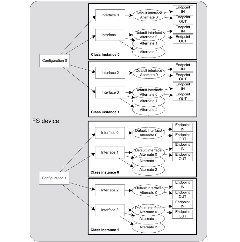
Figure - Multiple Class Instances - FS Device (2 Configurations and Multiple Interfaces) in the USB Device Classes page represents a more complex example. A full-speed device is composed of two configurations. The device has two functions which belong to the same class, but each function is described by two interfaces and has a pair of bidirectional endpoints.
In this example, two class instances are created. Each class instance is associated with a group of interfaces as opposed to Figure - Multiple Class Instances - FS Device (1 Configuration with 1 Interface) in the USB Device Classes page and Figure - Multiple Class Instances - FS Device (2 Configurations and Multiple Interfaces) in the USB Device Classes page where the class instance was associated with a single interface.
Figure - Multiple Class Instances - FS Device (2 Configurations and Multiple Interfaces)#
The code corresponding to Figure - Multiple Class Instances - FS Device (2 Configurations and Multiple Interfaces) in the USB Device Classes page is shown in Listing - Multiple Class Instances - FS Device (2 Configurations and Multiple Interfaces) in the USB Device Classes page. The error handling is omitted for clarity.
Listing - Multiple Class Instances - FS Device (2 Configurations and Multiple Interfaces)#
RTOS_ERR err;
CPU_INT08U class_0;
CPU_INT08U class_1;
USBD_XXXX_QTY_CFG qty_cfg;
qty_cfg.ClassInstanceQty = 2u;
qty_cfg.ConfigQty = 2u;
USBD_XXXX_Init(&qty_cfg, &err); (1)
class_0 = USBD_XXXX_Add(&err); (2)
class_1 = USBD_XXXX_Add(&err); (3)
USBD_XXXX_ConfigAdd(class_0, dev_nbr, cfg_0, &err); (4)
USBD_XXXX_ConfigAdd(class_1, dev_nbr, cfg_0, &err); (5)
USBD_XXXX_ConfigAdd(class_0, dev_nbr, cfg_1, &err); (6)
USBD_XXXX_ConfigAdd(class_1, dev_nbr, cfg_1, &err); (6)(1) Initialize the class. Any internal variables, structures, and class ports will be initialized.
(2) Create the class instance, class_0. The function USBD_XXXX_Add() allocates a class control structure associated with class_0.
(3) Create the class instance, class_1. The function USBD_XXXX_Add() allocates another class control structure associated with class_1.
(4) Add the class instance, class_0, to the configuration, cfg_0. USBD_XXXX_ConfigAdd() will create the interface 0, interface 1, alternate interfaces, and the associated IN and OUT endpoints. The class instance number, class_0, will be used for any data communication on interface 0 or interface 1.
(5) Add the class instance, class_1, to the configuration, cfg_0. USBD_XXXX_ConfigAdd() will create the interface 2, interface 3 and their associated IN and OUT endpoints. The class instance number, class_1, will be used for any data communication on interface 2 or interface 3.
(6) Add the same class instances, class_0 and class_1, to the other configuration, cfg_1.
USB Device CDC ACM Class#
This section describes the Communications Device Class (CDC) class and the associated CDC subclass supported by Micrium's USB Device stack. Micrium OS USB-Device currently supports the Abstract Control Model (ACM) subclass, which is commonly used for serial emulation.
CDC includes various telecommunication and networking devices. Telecommunication devices encompass analog modems, analog and digital telephones, ISDN terminal adapters, etc. For example, networking devices contain ADSL and cable modems, Ethernet adapters, and hubs. CDC defines a framework to encapsulate existing communication services standards, such as V.250 (for modems over telephone network) and Ethernet (for local area network devices), using a USB link. A communication device is in charge of device management, call management when needed, and data transmission.
CDC defines seven major groups of devices. Each group belongs to a model of communication which may include several subclasses. Each group of devices has its own specification document besides the CDC base class. The seven groups are:
Public Switched Telephone Network (PSTN), devices including voiceband modems, telephones, and serial emulation devices.
Integrated Services Digital Network (ISDN) devices, including terminal adaptors and telephones.
Ethernet Control Model (ECM) devices, including devices supporting the IEEE 802 family (ex.: cable and ADSL modems, WiFi adapters).
Asynchronous Transfer Mode (ATM) devices, including ADSL modems and other devices connected to ATM networks (workstations, routers, LAN switches).
Wireless Mobile Communications (WMC) devices, including multi-function communications handset devices used to manage voice and data communications.
Ethernet Emulation Model (EEM) devices which exchange Ethernet-framed data.
Network Control Model (NCM) devices, including high-speed network devices (High Speed Packet Access modems, Line Terminal Equipment)
The CDC and the associated subclass implementation complies with the following specifications:
Universal Serial Bus, Class Definitions for Communications Devices, Revision 1.2, November 3 2010.
Universal Serial Bus, Communications, Subclass for PSTN Devices, Revision 1.2, February 9 2007.
USB Device CDC Base Class Overview#
A CDC device is composed of the following interfaces to implement communication capability:
Communications Class Interface (CCI): responsible for the device management and optionally the call management. The device management enables the general configuration and control of the device and the notification of events to the host. The call management enables calls establishment and termination. Call management might be multiplexed through a DCI. A CCI is mandatory for all CDC devices. It identifies the CDC function by specifying the communication model supported by the CDC device. The interface(s) following the CCI can be any defined USB class interface, such as Audio or a vendor-specific interface. The vendor-specific interface is represented specifically by a DCI.
Data Class Interface (DCI): responsible for data transmission. The data transmitted and/or received do not follow a specific format. Data could be raw data from a communication line, data following a proprietary format, etc. All the DCIs following the CCI can be seen as subordinate interfaces.
A CDC device must have at least one CCI and zero or more DCIs. One CCI and any subordinate DCI together provide a feature to the host. This capability is also referred to as a function. In a CDC composite device, you could have several functions. Therefore, the device would be composed of several sets of CCI and DCI(s) as shown in Figure - CDC Composite Device in the USB Device CDC Base Class Overview page.
Figure - CDC Composite Device#

A CDC device is likely to use the following combination of endpoints:
A pair of control IN and OUT endpoints called the default endpoint.
An optional bulk or interrupt IN endpoint.
A pair of bulk or isochronous IN and OUT endpoints.
Table - CDC Endpoint Usage in the USB Device CDC Base Class Overview page indicates the usage of the different endpoints and by which interface of the CDC they are used:
Table - CDC Endpoint Usage#
Endpoint | Direction | Interface | Usage |
|---|---|---|---|
Control IN | Device-to-host | CCI | Standard requests for enumeration, class-specific requests, device management, and optionally call management. |
Control OUT | Host-to-device | CCI | Standard requests for enumeration, class-specific requests, device management, and optionally call management. |
Interrupt or bulk IN | Device-to-host | CCI | Events notification, such as ring detect, serial line status, network status. |
Bulk or isochronous IN | Device-to-host | DCI | Raw or formatted data communication. |
Bulk or isochronous OUT | Host-to-device | DCI | Raw or formatted data communication. |
Most communication devices use an interrupt endpoint to notify the host of events. Isochronous endpoints should not be used for data transmission when a proprietary protocol relies on data retransmission in case of USB protocol errors. Isochronous communication can inherently loose data since it has no retry mechanisms.
The seven major models of communication encompass several subclasses. A subclass describes the way the device should use the CCI to handle the device management and call management. Table - CDC Subclasses in the USB Device CDC Base Class Overview page shows all the possible subclasses and the communication model they belong to.
Table - CDC Subclasses#
Subclass | Communication model | Example of devices using this subclass |
|---|---|---|
Direct Line Control Model | PSTN | Modem devices directly controlled by the USB host |
Abstract Control Model | PSTN | Serial emulation devices, modem devices controlled through a serial command set |
Telephone Control Model | PSTN | Voice telephony devices |
Multi-Channel Control Model | ISDN | Basic rate terminal adaptors, primary rate terminal adaptors, telephones |
CAPI Control Model | ISDN | Basic rate terminal adaptors, primary rate terminal adaptors, telephones |
Ethernet Networking Control Model | ECM | DOC-SIS cable modems, ADSL modems that support PPPoE emulation, Wi-Fi adaptors (IEEE 802.11-family), IEEE 802.3 adaptors |
ATM Networking Control Model | ATM | ADSL modems |
Wireless Handset Control Model | WMC | Mobile terminal equipment connecting to wireless devices |
Device Management | WMC | Mobile terminal equipment connecting to wireless devices |
Mobile Direct Line Model | WMC | Mobile terminal equipment connecting to wireless devices |
OBEX | WMC | Mobile terminal equipment connecting to wireless devices |
Ethernet Emulation Model | EEM | Devices using Ethernet frames as the next layer of transport. Not intended for routing and Internet connectivity devices |
Network Control Model | NCM | IEEE 802.3 adaptors carrying high-speed data bandwidth on network |
USB Device CDC ACM Class Resource Needs from Core#
Each time you add a CDC ACM class instance to a USB configuration via a call to the function USBD_ACM_SerialConfigAdd(), the following resources will be allocated from the core.
Resource | Quantity |
|---|---|
Interfaces | 2 |
Alternate interfaces | 2 |
Endpoint descriptors | 3 |
Interface groups | 1 |
USB Device CDC ACM Class Example Applications#
CDC ACM Class Terminal Example#
This example emulates a USB-to-Serial adapter that displays a simple menu on a serial terminal. The menu allows you to send single or multiple characters to the adapter. The data is then sent back by the adapter, thereby creating a loopback.
Location#
The example implementation is located in /examples/usb/device/all/ex_usbd_cdc_acm_terminal.c.
To execute it, you will also need some files on the host side. The files can be downloaded from the Micrium web site .
To install the Windows driver for the device, use the .inf file from the Windows application files located in /micrium_usb_dev_host_app/OS/Windows/CDC/INF.
Running the Demo Application#
In this section, we will assume Windows is the host operating system. Upon connection of your CDC ACM device, Windows will enumerate your device and load the native driver usbser.sys to handle the device communication. The first time you connect your device to the host, you must indicate to Windows which driver to load using an INF file (refer to the About INF Files section for more details about INF files). The INF file tells Windows to load the usbser.sys driver. Indicating the INF file to Windows has to be done only once. Windows will then automatically recognize the CDC ACM device and load the proper driver for any new connection. The process of indicating the INF file may vary according to the Windows operating system version:
Windows XP directly opens the Found New Hardware Wizard. Follow the different steps of the wizard until you reach the page where you can indicate the path of the INF file.
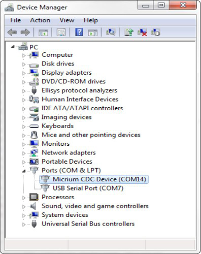
Windows Vista and later won’t open a “Found New Hardware Wizard”. They will only indicate that no driver was found for the vendor device. You have to manually open the wizard. When you open the Device Manager, your CDC ACM device should appear with a yellow icon. Right-click on your device and choose ‘Update Driver Software...’ to open the wizard. Follow the different steps of the wizard until you reach the page where you can indicate the path of the INF file.
The INF file is located in:
/micrium_usb_dev_host_app/OS/Windows/CDC/INF
Refer to the About INF Files section for more details about how to edit the INF file to match your Vendor ID (VID) and Product ID (PID). By default, the provided INF files define 0xFFFE for VID and 0x1234 for PID. Once the driver is loaded, Windows creates a virtual COM port as shown in Figure - Windows Device Manager and Created Virtual COM Port in the USB Device CDC ACM Class Example Applications page.
Figure - Windows Device Manager and Created Virtual COM Port#
The usbser.sys driver is already digitally signed by Windows. Micrium provides only an INF file, usbser.inf, telling Windows that your device uses that driver. Under Windows 7, providing this INF file was sufficient to load the driver usbser.sys for managing the CDC device. Windows 7 would display a warning message saying that the publisher of the driver can’t be verified but it was possible to continue the driver loading. Since Windows 8.x, Microsoft has enforced by default the loading of digitally signed driver packages. This is called Driver Signature Enforcement. Windows 8.x won’t let you load the CDC driver if the driver package is not fully signed. The Micrium CDC driver package is composed of usbser.inf (unsigned) and usbser.sys (signed). Basically, Windows 8.x requires a digitally signed INF file.
For development purposes, it is possible to disable the Driver Signature Enforcement. You can follow the instructions described on this page and you will be able to load the CDC driver and communicate with your USB device.
For your USB product release, you will have to follow the official procedure from Microsoft to sign the driver package (INF file + usbser.sys). The procedure is called the Release-Signing and is described here .
Micrium cannot provide an already-signed CDC driver package that would avoid disabling the Driver Signature Enforcement feature because the INF file contains a Vendor and Product IDs specific to the USB device manufacturer. For your USB product, the INF file must contain an official Vendor ID assigned to your company by the USB Implementer Forum. Micrium does not possess an official USB vendor ID. It is the customer’s responsibility to go through the official signing process as you are the USB device manufacturer.
Note that this restriction does not exist anymore under Windows 10 and later as the INF file usbser.sys is now natively digitally signed by Microsoft.
Figure - Serial Demo in the USB Device CDC ACM Class Example Applications page presents the steps to follow to use the serial demo.
Figure - Serial Demo#
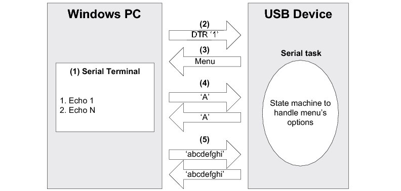
(1) Open a serial terminal (for instance, HyperTerminal). Open the COM port matching to your CDC ACM device with the serial settings (baud rate, stop bits, parity and data bits) you want. This operation will send a series of CDC ACM class-specific requests (GET_LINE_CODING, SET_LINE_CODING, SET_CONTROL_LINE_STATE) to your device. Note that Windows Vista and later don’t provide HyperTerminal anymore. You may use other free serial terminals such TeraTerm (http://ttssh2.sourceforge.jp/), Hercules (http://www.hw-group.com/products/hercules/index_en.html), RealTerm (http://realterm.sourceforge.net/), etc.
(2) In order to start the communication with the serial task on the device side, the Data Terminal Ready (DTR) signal must be set and sent to the device. The DTR signal prevents the serial task from sending characters if the terminal is not ready to receive data. Sending the DTR signal may vary depending on your serial terminal. For example, HyperTerminal sends a properly set DTR signal automatically upon opening of the COM port. Hercules terminal allows you to set and clear the DTR signal from the graphical user interface (GUI) with a checkbox. Other terminals do not permit to set/clear DTR or the DTR set/clear’s functionality is difficult to find and to use.
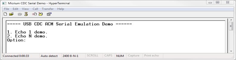
(3) Once the serial task receives the DTR signal, the task sends a menu to the serial terminal with two options as presented in Figure - CDC Serial Demo Menu in HyperTerminal in the USB Device CDC ACM Class Example Applications page.
(4) The menu option #1 is the Echo 1 demo. It allows you to send one unique character to the device. This character is received by the serial task and sent back to the host.
(5) The menu option #2 is the Echo N demo. It allows you to send several characters to the device. All the characters are received by the serial task and sent back to the host. The serial task can receive a maximum of 512 characters.
Figure - CDC Serial Demo Menu in HyperTerminal
To support the two demos, the serial task implements a state machine as shown in Figure - Serial Demo State Machine in the USB Device CDC ACM Class Example Applications page. Basically, the state machine has two paths corresponding to the user choice in the serial terminal menu.
Figure - Serial Demo State Machine#

(1) Once the DTR signal has been received, the serial task is in the MENU state.
(2) If you choose the menu option #1, the serial task will echo back any single character sent by the serial terminal as long as “Ctrl+C” is not pressed.
(3) If you choose the menu option #2, the serial task will echo all the received characters sent by the serial terminal as long as “Ctrl+C” is not pressed.
Table - Serial Terminals and CDC Serial Demo in the USB Device CDC ACM Class Example Applications page shows four possible serial terminals which you may use to test the CDC ACM class.
Table - Serial Terminals and CDC Serial Demo#
Terminal | DTR set/clear | Menu option(s) usable |
|---|---|---|
HyperTerminal | Yes (properly set DTR signal automatically sent upon COM port opening) | 1 and 2 |
Hercules | Yes (a checkbox in the GUI allows you to set/clear DTR) | 1 and 2 |
RealTerm | Yes (Set/Clear DTR buttons in the GUI) | 1 and 2 |
TeraTerm | Yes (DTR can be set using a macro. GUI does NOT allows you to set/clear DTR easily) | 1 and 2 |
API#
This example offers only one API named Ex_USBD_ACM_SerialInit(). This function is normally called from a USB device core example.
USB Device CDC ACM Subclass Overview#
The CDC base class is composed of a Communications Class Interface (CCI) and Data Class Interface (DCI), and this is discussed in detail in the section USB Device CDC Base Class Overview . This section discusses a CCI of type ACM. It consists of a default endpoint for the management element and an interrupt endpoint for the notification element. A pair of bulk endpoints is used to carry unspecified data over the DCI.
The ACM subclass is used by two types of communication devices:
Devices supporting AT commands (for instance, voiceband modems).
Serial emulation devices which are also called Virtual COM port devices.
There are several subclass-specific requests for the ACM subclass. They allow you to control and configure the device. The complete list and description of all ACM requests can be found in the specification “Universal Serial Bus, Communications, Subclass for PSTN Devices, revision 1.2, February 9, 2007”, section 6.2.2.
From this list, Micrium’s ACM subclass supports the following:
Table - ACM Requests Supported by Micrium#
Subclass request | Description |
|---|---|
SetCommFeature | The host sends this request to control the settings for a given communications feature. Not used for serial emulation. |
GetCommFeature | The host sends this request to get the current settings for a given communications feature. Not used for serial emulation. |
ClearCommFeature | The host sends this request to clear the settings for a given communications feature. Not used for serial emulation. |
SetLineCoding | The host sends this request to configure the ACM device settings: baud rate, number of stop bits, parity type and number of data bits. For a serial emulation, this request is sent automatically by a serial terminal each time you configure the serial settings for an open virtual COM port. |
GetLineCoding | The host sends this request to get the current ACM settings (baud rate, stop bits, parity, data bits). For a serial emulation, serial terminals send this request automatically during virtual COM port opening. |
SetControlLineState | The host sends this request to control the carrier for half-duplex modems and indicate that Data Terminal Equipment (DTE) is ready or not. In the serial emulation case, the DTE is a serial terminal. For a serial emulation, certain serial terminals allow you to send this request with the controls set. |
SetBreak | The host sends this request to generate an RS-232 style break. For a serial emulation, certain serial terminals allow you to send this request. |
Micrium’s ACM subclass uses the interrupt IN endpoint to notify the host about the current serial line state. The serial line state is a bitmap informing the host about:
Data discarded because of overrun
Parity error
Framing error
State of the ring signal detection
State of break detection mechanism
State of transmission carrier
State of receiver carrier detection
Micrium’s ACM subclass implementation complies with the following specification:
Universal Serial Bus, Communications, Subclass for PSTN Devices, revision 1.2, February 9, 2007.
USB Device CDC ACM Class Configuration#
This section discusses how to configure the CDC ACM Class (Communication Device Class, Abstract Control Model). There are two groups of configuration parameters:
USB Device CDC ACM Class Run-Time Application Specific Configurations#
Initialization#
CDC Base Class#
Before initializing the USB Device CDC ACM class module, you must first initialize the CDC base class by calling the function USBD_CDC_Init(). This function uses one configuration argument, as follows:
####### p_qty_cfg
p_cfg is a pointer to a configuration structure of type USBD_CDC_QTY_CFG. Its purpose is to inform the USB device module about how many USB CDC objects to allocate.
Table - USBD CDC QTY CFG configuration structure in the USB Device CDC ACM Class Run-Time Application Specific Configurations page describes each configuration field available in this configuration structure.
Table - USBD_CDC_QTY_CFG configuration structure#
Field | Description |
|---|---|
.ClassInstanceQty | Number of class instances you will allocate via a call to the function USBD_ACM_SerialAdd(). |
.ConfigQty | Number of configurations. ACM class instances can be added to one or more configurations via a call to the USBD_ACM_SerialConfigAdd(). |
.DataIF_Qty | Total number of data interfaces (DCI) for all the CDC functions. Each CDC ACM function added via a call to the function USBD_ACM_SerialAdd() will add a data interface. |
ACM Subclass#
Once the CDC base class is initialized, the ACM subclass can be initialized by calling the function USBD_ACM_SerialInit(). This function takes one configuration argument that is described as follows.
subclass_instance_qty#
subclass_instance_qty configures the number of subclass instances you will allocate via a call to the function USBD_ACM_SerialAdd().
Optional Configurations#
This section describes the configurations that are optional. If you do not set them in your application, the default configurations will apply.
CDC Base Class#
The default values can be retrieved via the structure USBD_CDC_InitCfgDflt.
Note that these configurations must be set before you call the function USBD_CDC_Init(). |
|---|
Memory segment#
This module allocates some control data. It has the ability to allocate this data from a specified memory segment.
Type | Function to call | Default | Field from default configuration structure |
|---|---|---|---|
MEM_SEG* | USBD_CDC_ConfigureMemSeg() | .MemSegPtr |
ACM Subclass#
The default values can be retrieved via the structure USBD_CDC_ACM_SerialInitCfgDflt.
Note: these configurations must be set before you call the function USBD_ACM_SerialInit(). |
|---|
Buffer Alignment#
This module allocates buffers used for data transfers with the host. You may need address alignment for these buffers, depending on your USB controller. If you use more than one USB controller, you must set the alignment to the largest value.
Type | Function to call | Default | Field from default configuration structure |
|---|---|---|---|
CPU_SIZE_T | USBD_ACM_SerialConfigureBufAlignOctets() | Size of cache line, or CPU alignment, if no cache. | .BufAlignOctets |
Memory Segments#
The USB Device module allocates control data and buffers used for data transfers with the host. It has the ability to use a different memory segment for the control data and for the data buffers.
Type | Function to call | Default | Field from default configuration structure |
|---|---|---|---|
MEM_SEG* | USBD_ACM_SerialConfigureMemSeg() | .MemSegPtr | |
MEM_SEG* | USBD_ACM_SerialConfigureMemSeg() | .MemSegBufPtr |
USB Device CDC ACM Class Instance Configurations#
This section defines the configurations related to the CDC ACM serial class instances.
Class Instance Creation#
Creating a CDC ACM serial class instance is done by calling the function USBD_ACM_SerialAdd(). This function takes two configuration arguments that are described here.
line_state_interval#
This is the interval (in milliseconds) that your CDC ACM serial class instance will report the line state notifications to the host. This value must be a power of two (1, 2, 4, 8, 16, etc).
call_mgmt_capabilities#
Call Management Capabilities bitmap. Possible values of the bitmap are:
Value (bit) | Description |
|---|---|
USBD_ACM_SERIAL_CALL_MGMT_DEV | Device handles call management itself. |
USBD_ACM_SERIAL_CALL_MGMT_DATA_CCI_DCI | Device can send/receive call management information over a Data Class interface. |
USB Device CDC ACM Class Programming Guide#
This section explains how to use the CDC Abstract Control Model class.
Initializing the USB Device CDC ACM Class#
To add CDC ACM class functionality to your device, you must first initialize the CDC base class and the ACM subclass by calling the functions USBD_CDC_Init() and USBD_ACM_SerialInit().
Listing - Example of initialization of CDC ACM class in the Initializing the USB Device CDC ACM Class page gives an example of a call to USBD_CDC_Init() and USBD_ACM_SerialInit() using default arguments. For more information about the configuration arguments to pass to these functions, see USB Device CDC ACM Class Run-Time Application Specific Configurations .
Listing - Example of initialization of CDC ACM class#
RTOS_ERR err;
USBD_CDC_QTY_CFG cdc_qty_cfg;
cdc_qty_cfg.ClassInstanceQty = 1u;
cdc_qty_cfg.ConfigQty = 2u;
cdc_qty_cfg.DataIF_Qty = 1u;
USBD_CDC_Init(&cdc_qty_cfg,
&err);
if (err.Code != RTOS_ERR_NONE) {
/* An error occurred. Error handling should be added here. */
}
USBD_ACM_SerialInit(1u
&err);
if (err.Code != RTOS_ERR_NONE) {
/* An error occurred. Error handling should be added here. */
}Adding a USB Device CDC ACM Class Instance to your Device#
To add CDC ACM class functionality to your device, you must create an instance, then add it to your device's configuration(s).
Creating a CDC ACM Class Instance#
Create a CDC ACM class instance by calling the function USBD_ACM_SerialAdd().
Listing - Creating a CDC ACM function via USBD ACM SerialAdd() in the Adding a USB Device CDC ACM Class Instance to your Device page shows an example of how to create a CDC EEM class instance via USBD_CDC_EEM_Add().
Listing - Creating a CDC ACM function via USBD ACM SerialAdd()#
CPU_INT08U class_nbr;
RTOS_ERR err;
class_nbr = USBD_ACM_SerialAdd(64u,
USBD_ACM_SERIAL_CALL_MGMT_DATA_CCI_DCI | USBD_ACM_SERIAL_CALL_MGMT_DEV
&err);
if (err.Code != RTOS_ERR_NONE) {
/* An error occurred. Error handling should be added here. */
}Adding the CDC ACM Class Instance to Your Device's Configuration(s)#
Once you have created a CDC ACM class instance, you can add it to a configuration by calling the function USBD_ACM_SerialConfigAdd().
Listing - Example of call to USBD ACM SerialConfigAdd() in the Adding a USB Device CDC ACM Class Instance to your Device page shows an example of a call to USBD_ACM_SerialConfigAdd().
Listing - Example of call to USBD ACM SerialConfigAdd()#
RTOS_ERR err;
USBD_ACM_SerialConfigAdd(class_nbr, (1)
dev_nbr, (2)
config_nbr_fs, (3)
&err);
if (err.Code != RTOS_ERR_NONE) {
/* An error occurred. Error handling should be added here. */
}
USBD_ACM_SerialConfigAdd(class_nbr, (4)
dev_nbr,
config_nbr_hs,
&err);
if (err.Code != RTOS_ERR_NONE) {
/* An error occurred. Error handling should be added here. */
}(1) Class number to add to the configuration returned by USBD_ACM_SerialAdd().
(2) Device number returned by USBD_DevAdd().
(3) Configuration number (here adding it to a Full-Speed configuration).
(4) Adding the same class instance to the High-Speed configuration. This should be done only if you have a High-Speed device.
Registering Event Notification Callbacks#
The CDC ACM Serial class can notify your application of any changes in line control or coding via two notification callback functions: USBD ACM SerialLineCtrlReg() and USBD_ACM_SerialLineCodingReg(). Note that this step is optional. Listing - CDC ACM callbacks registration in the Adding a USB Device CDC ACM Class Instance to your Device page illustrates the use of the callback registration functions. Listing - CDC ACM callbacks implementation in the Adding a USB Device CDC ACM Class Instance to your Device page shows an example of implementation of the callback functions.
Listing - CDC ACM callbacks registration#
USBD_ACM_SerialLineCodingReg(class_nbr,
App_USBD_ACM_SerialLinceCodingChngd,
DEF_NULL,
&err);
USBD_ACM_SerialLineCtrlReg(class_nbr,
App_USBD_ACM_SerialLineCtrlChngd,
DEF_NULL,
&err);Listing - CDC ACM callbacks implementation#
CPU_BOOLEAN App_USBD_ACM_SerialLinceCodingChngd (CPU_INT08U subclass_nbr,
USBD_ACM_SERIAL_LINE_CODING *p_line_coding,
void *p_arg)
{
CPU_INT32U baudrate_new;
CPU_INT08U parity_new;
CPU_INT08U stop_bits_new;
CPU_INT08U data_bits_new;
/* TODO: Apply new line coding.*/
baudrate_new = p_line_coding->BaudRate;
parity_new = p_line_coding->Parity;
stop_bits_new = p_line_coding->StopBits;
data_bits_new = p_line_coding->DataBits;
return (DEF_OK); (1)
}
void App_USBD_ACM_SerialLineCtrlChngd (CPU_INT08U subclass_nbr,
CPU_INT08U event,
CPU_INT08U event_chngd,
void *p_arg)
{
CPU_BOOLEAN rts_state;
CPU_BOOLEAN rts_state_chngd;
CPU_BOOLEAN dtr_state;
CPU_BOOLEAN dtr_state_chngd;
CPU_BOOLEAN brk_state;
CPU_BOOLEAN brk_state_chngd;
/* TODO: Apply new line control. */
rts_state = DEF_BIT_IS_SET(event, USBD_ACM_SERIAL_CTRL_RTS);
rts_state_chngd = DEF_BIT_IS_SET(event_chngd, USBD_ACM_SERIAL_CTRL_RTS);
dtr_state = DEF_BIT_IS_SET(event, USBD_ACM_SERIAL_CTRL_DTR);
dtr_state_chngd = DEF_BIT_IS_SET(event_chngd, USBD_ACM_SERIAL_CTRL_DTR);
brk_state = DEF_BIT_IS_SET(event, USBD_ACM_SERIAL_CTRL_BREAK);
brk_state_chngd = DEF_BIT_IS_SET(event_chngd, USBD_ACM_SERIAL_CTRL_BREAK);
}(1) It is important to return DEF_FAIL to this function if the line coding applying failed. Otherwise, return DEF_OK.
Communicating using the CDC ACM Class#
Serial Status#
Line Coding#
The USB host controls the line coding (baud rate, parity, etc) of the CDC ACM device. When necessary, the application is responsible for setting the line coding.
There are three functions provided to retrieve and set the current line coding. They are described in Table - CDC ACM Line Coding Functions in the Communicating using the CDC ACM Class page.
Table - CDC ACM Line Coding Functions#
Function | Description |
|---|---|
USBD_ACM_SerialLineCodingGet() | Your application can get the current line coding settings set either from the host with SetLineCoding requests or with the function USBD_ACM_SerialLineCodingSet(). |
USBD_ACM_SerialLineCodingSet() | Your application can set the line coding. The host can retrieve the settings with the GetLineCoding request. |
USBD_ACM_SerialLineCodingReg() | Your application registers a callback called by the ACM subclass upon reception of the SetLineCoding request. Your application can perform any specific operations. For more information, see USB Device CDC ACM Class Instance Configurations . |
Line Control#
The USB host controls the line control (RTS and DTR pins, break signal, ...) of the CDC ACM device. W hen necessary, your application is responsible for applying the line controls.
There are two functions provided to retrieve and set the current line controls. They are described in Table - CDC ACM Line Control Functions in the Communicating using the CDC ACM Class page.
Table - CDC ACM Line Control Functions#
Function | |
|---|---|
USBD_ACM_SerialLineCtrlGet() | Your application can get the current control line state set by the host with the SetControlLineState request. |
USBD_ACM_SerialLineCtrlReg() | Your application registers a callback called by the ACM subclass upon reception of the SendBreak or SetControlLineState requests. Your application can perform any specific operations. See USB Device CDC ACM Class Instance Configurations for more information. |
Line State#
The USB host retrieves the line state at a regular interval. Your application must update the line state each time it changes. W hen necessary, your application is responsible for setting the line state.
There are two functions provided to retrieve and set the current line controls. They are described in Table - CDC ACM Line State Functions in the Communicating using the CDC ACM Class page.
Table - CDC ACM Line State Functions#
Function | |
|---|---|
USBD_ACM_SerialLineStateSet() | Your application can set any line state event(s). While setting the line state, an interrupt IN transfer is sent to the host to inform about it a change in the serial line state. |
USBD_ACM_SerialLineStateClr() | Application can clear two events of the line state: transmission carrier and receiver carrier detection. All the other events are self-cleared by the ACM serial emulation subclass. |
Subclass Instance Communication#
Micrium’s ACM subclass offers the following functions to communicate with the host. For more details about the functions’ parameters, see the CDC ACM Subclass Functions reference.
Function name | Operation |
|---|---|
USBD_ACM_SerialRx() | Receives data from host through a bulk OUT endpoint. This function is blocking. |
USBD_ACM_SerialTx() | Sends data to host through a bulk IN endpoint. This function is blocking. |
Table - CDC ACM Communication API Summary
USBD_ACM_SerialRx() and USBD_ACM_SerialTx() provide synchronous communication, which means that the transfer is blocking. This means that, upon calling the function, the application blocks until the transfer is complete with or without an error. A timeout can be specified to avoid waiting forever. Listing - Serial Read and Write Example in the Communicating using the CDC ACM Class page shows a read and write example that receives data from the host using the bulk OUT endpoint and sends data to the host using the bulk IN endpoint.
Listing - Serial Read and Write Example#
CPU_INT08U rx_buf[2];
CPU_INT08U tx_buf[2];
RTOS_ERR err;
(void)USBD_ACM_SerialRx(subclass_nbr, (1)
rx_buf, (2)
2u,
0u, (3)
&err);
if (err.Code != RTOS_ERR_NONE) {
/* An error occurred. Error handling should be added here. */
}
(void)USBD_ACM_SerialTx(subclass_nbr, (1)
tx_buf, (4)
2u,
0u, (3)
&err);
if (err.Code != RTOS_ERR_NONE) {
/* An error occurred. Error handling should be added here. */
}(1) The class instance number created with USBD_ACM_SerialAdd() provides an internal reference to the ACM subclass to route the transfer to the proper bulk OUT or IN endpoint.
(2) Your application must ensure that the buffer provided to the function is large enough to accommodate all the data. Otherwise, synchronization issues might happen.
(3) To avoid an infinite blocking situation, specify a timeout expressed in milliseconds. A value of ‘0’ makes the application task wait forever.
(4) The application provides the initialized transmit buffer.
USB Device CDC EEM Class#
This section describes the Communication Device Class Ethernet Emulation Model subclass (CDC EEM) supported by Micrium OS USB Device. CDC EEM is a protocol that allows the usage of the USB as an Ethernet link. The device is seen by the host as a device on an Ethernet network, so all typical applications can be run on the device (FTP, HTTP, DHCP, etc.).
Microsoft Windows and Apple Mac OS do not provide any driver for CDC EEM devices, but commercial drivers can easily be found. Linux supports CDC EEM devices since kernel version 2.6.34.
CDC EEM represents the physical layer in the OSI model. It requires a network stack to implement higher layers. Micrium OS Network module offers an Ethernet driver for Micrium OS USB Device's CDC EEM subclass.
The CDC EEM implementation offered by Micrium OS USB Device is in compliance with the following specification:
Universal Serial Bus Communications Class Subclass Specification for Ethernet Emulation Model Devices, Revision 1.0 February 2, 2005.
USB Device CDC EEM Class Overview#
This page presents an overview of the CDC EEM protocol.
Overview#
A CDC EEM device is composed of the following endpoints:
A pair of Bulk IN and OUT endpoints.
Table - CDC EEM Subclass Endpoints Usage in the USB Device CDC EEM Class Overview page describes the usage of the different endpoints:
Table - CDC EEM Subclass Endpoints Usage#
Endpoint | Direction | Usage |
|---|---|---|
Bulk In | Device-to-host | Send Ethernet frames and commands to host. |
Bulk OUT | Host-to-device | Receive Ethernet frames and commands from host. |
CDC EEM Messages#
CDC EEM defines a header that is prepended to each message sent to / received from the host. The CDC EEM header has a size of two bytes. A USB transfer on the Bulk endpoints can contain multiple EEM messages. An EEM message can also span on multiple USB transfers.
CDC EEM Message Format#
Table - CDC EEM Message Format in the USB Device CDC EEM Class Overview page describes the content of a CDC EEM message.
Table - CDC EEM Message Format#
Bytes | 0..1 | 2..N |
|---|---|---|
Content | Header | Payload (optional) |
CDC EEM Header Format#
Table - CDC EEM Header Format in the USB Device CDC EEM Class Overview page describes the content of a CDC EEM header.
Table - CDC EEM Header Format#
Bit | 15 | 14 .. 0 |
|---|---|---|
Content | bmType | Depends on bmType value |
bmType represents the message type, either a regular Ethernet frame or a CDC EEM specific command.
CDC EEM Data Header Format#
Table - CDC EEM Data Header Format in the USB Device CDC EEM Class Overview page describes the content of a CDC EEM data message header.
Table - CDC EEM Data Header Format#
Bit | 15 | 14 | 13 .. 0 |
|---|---|---|---|
Content | bmType (0) | bmCRC | Length of Ethernet frame |
bmCRC indicates if the CRC was calculated on the Ethernet frame. If not, CRC is set to 0xDEADBEEF.
CDC EEM Command Header Format#
Table - CDC EEM Command Header Format in the USB Device CDC EEM Class Overview page describes the content of a CDC EEM command message header. Note that the EEM commands provide USB local link management. This management is opaque to the network stack.
Table - CDC EEM Command Header Format#
Bit | 15 | 14 | 13 .. 11 | 10 .. 0 |
|---|---|---|---|---|
Content | bmType (1) | bmReserved (0) | bmEEMCmd | bmEEMCmdParam |
bmEEMCmd represents the command code to execute.
bmEEMCmdParam contains command data. The format depends on the bmEEMCmd.
For more information on CDC EEM messages format, see "Universal Serial Bus Communications Class Subclass Specification for Ethernet Emulation Model Devices" revision 1.0. February 2, 2005, section 5.1.
USB Device CDC EEM Class Resource Needs from Core#
Each time you add a CDC EEM class instance to a USB configuration (via a call to the function USBD_CDC_EEM_ConfigAdd()), the following resources will be allocated from the core.
Resource | Quantity |
|---|---|
Interfaces | 1 |
Alternate interfaces | 1 |
Endpoint descriptors | 2 |
Interface groups | 0 |
USB Device CDC EEM Class Example Applications#
This example creates and opens a Micrium OS Network Ethernet interface that uses the CDC EEM USB device class as a transport layer.
This example will allow you to accomplish the following tasks:
Initialize the CDC EEM class
Create and register a CDC EEM class instance
Add the CDC EEM class instance to the Full-Speed configuration
Add the CDC EEM class instance to the High-Speed configuration (if available)
Add the new Ethernet Interface created from the CDC EEM class instance to Micrium OS Network
Start the Ethernet interface
Location#
The example implementation is located in /examples/usb/device/all/ex_usbd_cdc_eem_net.c.
Running the Demo Application#
Currently, only the Linux operating system has built-in support for CDC EEM devices. Note that some third-party commercial drivers can be found for Microsoft Windows and Apple macOS.
Once connected to a Linux host, the operating system will add a new network interface called "usbx" (where x is a number starting from 0). The command ifconfig can be used from a terminal prompt to see the different network interfaces available, and to set a static IP address to the "usbx" interface. This will be necessary if you don't have a DHCP server on your target.
Once done, you should be ready to perform ping commands from a terminal prompt and use any other application implemented on your device (HTTP, FTP, etc).
API#
This example offers only one API named Ex_USBD_CDC_EEM_Init(). This function is normally called from a USB device core example.
USB Device CDC EEM Class Configuration#
To configure the CDC EEM class, use the following configuration parameters:
USB Device CDC EEM Class Run-time Application Specific Configurations#
Class Initialization#
To initialize the Micrium OS USB Device CDC EEM class, you call the function USBD_CDC_EEM_Init(). This function takes one configuration argument, which is described below.
p_qty_cfg#
p_qty_cfgis a pointer to a configuration structure of type USBD_CDC_EEM_QTY_CFG. Its purpose is to inform the USB device module on how many USB CDC EEM objects to allocate.
Table - USBD_CDC_EEM_QTY_CFG configuration structure in the USB Device CDC EEM Class Run-time Application Specific Configurations page describes each configuration field available in this configuration structure.
Table - USBD CDC EEM QTY CFG configuration structure#
Field | Description | Recommended value |
|---|---|---|
.ClassInstanceQty | Number of class instances you will allocate via a call to the function USBD_CDC_EEM_Add(). | 1 |
.ConfigQty | Number of configurations. EEM class instances can be added to one or more configuration via a call to the function USBD_CDC_EEM_ConfigAdd(). | 2 |
Optional Configurations#
This section describes the configurations that are optional. If you do not set them in your application, the default configurations will apply.
The default values can be retrieved via the structure USBD_CDC_EEM_InitCfgDflt.
Note: these configurations must be set before you call the function USBD_CDC_EEM_Init(). |
|---|
Buffer Alignment#
This module allocates some buffers used for data transfers with the host. You may need a specific address alignment for these buffers depending on your USB controller. If you use more than one USB controller, you must set the alignment to the largest value.
Type | Function to call | Default | Field from default configuration structure |
|---|---|---|---|
CPU_SIZE_T | USBD_CDC_EEM_ConfigureBufAlignOctets() | Size of cache line, or CPU alignment, if no cache. | .BufAlignOctets |
Receive Buffers#
Configures the quantity and the length, in octets, of the receive buffers for each CDC EEM function. The receive buffers must have a length of at least 1520 octets.
Unless your USB driver supports URB queuing, you must set the receive buffer quantity to 1.
Type | Function to call | Default | Field from default configuration structure |
|---|---|---|---|
CPU_INT08U | USBD_CDC_EEM_ConfigureRxBuf() | 1 buffer of 1520 octets. | .RxBufQty |
CPU_INT32U | USBD_CDC_EEM_ConfigureRxBuf() | 1 buffer of 1520 octets. | .RxBufLen |
Echo Buffer Length#
Configures the length, in octets, of the buffer used to handle the echo requests.
Type | Function to call | Default | Field from default configuration structure |
|---|---|---|---|
CPU_INT16U | USBD_CDC_EEM_ConfigureEchoBufLen() | 64 octets. | .EchoBufLen |
Memory Segments#
This module allocates some control data and buffers used for data transfers with the host. It has the ability to use a different memory segment for the control data and for the data buffers.
Type | Function to call | Default | Field from default configuration structure |
|---|---|---|---|
MEM_SEG* | USBD_CDC_EEM_ConfigureMemSeg() | .MemSegPtr | |
MEM_SEG* | USBD_CDC_EEM_ConfigureMemSeg() | .MemSegBufPtr |
USB Device CDC EEM Class Programming Guide#
This section explains how to use the CDC EEM class.
Initializing the USB Device CDC EEM Class#
To add CDC EEM class functionality to your device, you must first initialize the class by calling the function USBD_CDC_EEM_Init().
Listing - Example of call to USBD_CDC_EEM_Init() in the Initializing the USB Device CDC EEM Class page shows an example of a call to USBD_CDC_EEM_Init() using default arguments. For more information about the configuration arguments to pass to USBD_CDC_EEM_Init(), see USB Device CDC EEM Class Run-time Application Specific Configurations .
Listing - Example of call to USBD CDC EEM Init()#
RTOS_ERR err;
USBD_CDC_EEM_QTY_CFG eem_qty_cfg;
eem_qty_cfg.ClassInstanceQty = 1u;
eem_qty_cfg.ConfigQty = 2u;
USBD_CDC_EEM_Init(&eem_qty_cfg,
&err);
if (err.Code != RTOS_ERR_NONE) {
/* An error occurred. Error handling should be added here. */
}Adding a USB Device CDC EEM Class Instance to your Device#
To add CDC EEM class functionality to your device, you must create an instance, then add it to your device's configuration(s).
Creating a CDC EEM Class Instance#
There are two ways to create a CDC EEM class instance. This can be done by either calling the function USBD_CDC_EEM_Add() or USBD_CDC_EEM_NetIF_Reg(). The function USBD_CDC_EEM_Add() will simply create a CDC EEM class instance and provide the class instance number.
On the other hand, the function USBD_CDC_EEM_NetIF_Reg() will create the CDC EEM class instance, add the network interface to the Platform Manager , and provide the interface name to the caller. The name allows you to add the network interface to Micrium OS Network (using the function NetIF_Ether_Add()) afterward.
The recommended method is to add a CDC EEM class instance (the explanation follows below). You must have the Micrium OS Network Ethernet module in your project to enable this function.
Listing - Creating a CDC EEM function via USBD_CDC_EEM_NetIF_Reg() in the Adding a USB Device CDC EEM Class Instance to your Device page shows an example of how to create a CDC EEM class instance via USBD_CDC_EEM_NetIF_Reg().
Listing - Creating a CDC EEM function via USBD CDC EEM NetIF Reg()#
CPU_INT08U class_nbr;
CPU_CHAR *net_if_name;
USBD_CDC_EEM_NET_IF_ETHER_CFG net_if_ether_cfg;
RTOS_ERR err;
net_if_ether_cfg.RxBufQty = 5u;
net_if_ether_cfg.TxBufQty = 5u;
net_if_ether_cfg.TxBufSmallLen = 128u;
net_if_ether_cfg.TxBufSmallQty = 2u;
Mem_Copy(net_if_ether_cfg.HW_AddrStr,
"12-34-56-78-9A-BC",
NET_IF_802x_ADDR_SIZE_STR);
class_nbr = USBD_CDC_EEM_NetIF_Reg(&net_if_name,
&net_if_ether_cfg,
&err);
if (err.Code != RTOS_ERR_NONE) {
/* An error occurred. Error handling should be added here. */
}Adding the CDC EEM Class Instance to Your Device's Configuration(s)#
Once you have created a CDC EEM class instance, you can add it to a configuration by calling the function USBD_CDC_EEM_ConfigAdd().
Listing - Example of call to USBD_CDC_EEM_ConfigAdd() in the Adding a USB Device CDC EEM Class Instance to your Device page shows an example of call to USBD_CDC_EEM_ConfigAdd().
Listing - Example of call to USBD CDC EEM ConfigAdd()#
RTOS_ERR err;
USBD_CDC_EEM_ConfigAdd(class_nbr, (1)
dev_nbr, (2)
config_nbr_fs, (3)
"CDC EEM Full-Speed Interface",
&err);
if (err.Code != RTOS_ERR_NONE) {
/* An error occurred. Error handling should be added here. */
}
USBD_CDC_EEM_ConfigAdd(class_nbr, (4)
dev_nbr,
config_nbr_hs,
"CDC EEM High-Speed Interface",
&err);
if (err.Code != RTOS_ERR_NONE) {
/* An error occurred. Error handling should be added here. */
}(1) Class number to add to the configuration returned by USBD_CDC_EEM_Add().
(2) Device number returned by USBD_DevAdd().
(3) Configuration number (here adding it to a Full-Speed configuration).
(4) Adding the same class instance to the High-Speed configuration. This should be done only if you have a High-Speed device.
USB Device HID Class#
This section describes the Human Interface Device (HID) class supported by Micrium OS USB Device.
The HID class encompasses devices used by humans to control computer operations: for example, keyboards, mice, pointing devices, and game devices.
The HID class can also be used in a composite device that contains controls such as knobs, switches, buttons, and sliders. For instance, mute and volume controls in an audio headset are controlled by the HID function of the headset. HID class can exchange data for any purpose using only control and interrupt transfers.
The HID class is one of the oldest and most widely-used USB classes. All the major host operating systems provide a native driver to manage HID devices, which is why a variety of vendor-specific devices work with the HID class. This class also includes various types of output items such as LEDs, audio, tactile feedback, etc.
The HID implementation complies with the following specifications:
Device Class Definition for Human Interface Devices (HID), 6/27/01, Version 1.11.
Universal Serial Bus HID Usage Tables, 10/28/2004, Version 1.12.
USB Device HID Class Overview#
Overview#
A HID device is composed of the following endpoints:
A pair of control IN and OUT endpoints called the default endpoint.
An interrupt IN endpoint.
An optional interrupt OUT endpoint.
Table - HID Class Endpoints Usage in the USB Device HID Class Overview page describes the usage of the different endpoints:
Table - HID Class Endpoints Usage#
Endpoint | Direction | Usage |
|---|---|---|
Control IN | Device-to-host | Standard requests for enumeration, class-specific requests, and data communication (Input, Feature reports sent to the host with GET_REPORT request). |
Control OUT | Host-to-device | Standard requests for enumeration, class-specific requests and data communication (Output, Feature reports received from the host with SET_REPORT request). |
Interrupt IN | Device-to-host | Data communication (Input and Feature reports). |
Interrupt OUT | Host-to-device | Data communication (Output and Feature reports). |
Report#
A host and a HID device exchange data using reports. A report contains formatted data giving information about controls and other physical entities of the HID device. A control is manipulable by the user and operates an aspect of the device. For instance, a control can be a button on a mouse or a keyboard, a switch, etc. Other entities inform the user about the state of certain device’s features. For instance, LEDs on a keyboard notify the user about the caps lock on, the numeric keypad active, etc.
The format and the use of a report data is understood by the host by analyzing the content of a Report descriptor. Analyzing the content is done by a parser. The Report descriptor describes the data provided by each control in a device. It is composed of items which are pieces of information about the device and consist of a 1-byte prefix and variable-length data. For more details about the item format, refer to “Device Class Definition for Human Interface Devices (HID) Version 1.11”, section 5.6 and 6.2.2.
There are three principal types of items:
Main item defines or groups certain types of data fields.
Global item describes data characteristics of a control.
Local item describes data characteristics of a control.
Each item type is defined by different functions. An item function can also be called a tag. An item function can be seen as a sub-item that belongs to one of the three principal item types. Table - Item’s Function Description for each Item Type in the USB Device HID Class Overview page gives a brief overview of the item’s functions in each item type. For a complete description of the items in each category, refer to “Device Class Definition for Human Interface Devices (HID) Version 1.11”, section 6.2.2.
Table - Item’s Function Description for each Item Type#
Item type | Item function | Description | |
|---|---|---|---|
Main | Input | Describes information about the data provided by one or more physical controls. | |
Main | Output | Describes data sent to the device. | |
Main | Feature | Describes device configuration information sent to or received from the device which influences the overall behavior of the device or one of its components. | |
Main | Collection | Group related items (Input, Output or Feature). | |
Main | End of Collection | Closes a collection. | |
Global | Usage Page | Identifies a function available within the device. | |
Global | Logical Minimum | Defines the lower limit of the reported values in logical units. | |
Global | Logical Maximum | Defines the upper limit of the reported values in logical units. | |
Global | Physical Minimum | Defines the lower limit of the reported values in physical units, that is the Logical Minimum expressed in physical units. | |
Global | Physical Maximum | Defines the upper limit of the reported values in physical units, that is the Logical Maximum expressed in physical units. | |
Global | Unit Exponent | Indicates the unit exponent in base 10. The exponent ranges from -8 to +7. | |
Global | Unit | Indicates the unit of the reported values. For instance, length, mass, temperature units, etc. | |
Global | Report Size | Indicates the size of the report fields in bits. | |
Global | Report ID | Indicates the prefix added to a particular report. | |
Global | Report Count | Indicates the number of data fields for an item. | |
Global | Push | Places a copy of the global item state table on the CPU stack. | |
Global | Pop | Replaces the item state table with the last structure from the stack. | |
Local | Usage | Represents an index to designate a specific Usage within a Usage Page. It indicates the vendor’s suggested use for a specific control or group of controls. A usage supplies information to an application developer about what a control is actually measuring. | |
Local | Usage Minimum | Defines the starting usage associated with an array or bitmap. | |
Local | Usage Maximum | Defines the ending usage associated with an array or bitmap. | |
Local | Designator Index | Determines the body part used for a control. Index points to a designator in the Physical descriptor. | |
Local | Designator Minimum | Defines the index of the starting designator associated with an array or bitmap. | |
Local | Designator Maximum | Defines the index of the ending designator associated with an array or bitmap. | |
Local | String Index | String index for a String descriptor. It allows a string to be associated with a particular item or control. | |
Local | String Minimum | Specifies the first string index when assigning a group of sequential strings to controls in an array or bitmap. | |
Local | String Maximum | Specifies the last string index when assigning a group of sequential strings to controls in an array or bitmap. | |
Local | Delimiter | Defines the beginning or end of a set of local items. |
A control’s data must define at least the following items:
Input, Output or Feature Main items.
Usage Local item.
Usage Page Global item.
Logical Minimum Global item.
Logical Maximum Global item.
Report Size Global item.
Report Count Global item.
Table - HID Class Endpoints Usage in the USB Device HID Class Overview page shows the representation of a Mouse Report descriptor content from a host HID parser perspective. The mouse has three buttons (left, right and wheel). The code presented in Listing - Mouse Report Descriptor Example in the USB Device HID Class Configuration page is an example of code implementation corresponding to this mouse Report descriptor representation.
Figure - Report Descriptor Content from a Host HID Parser View#
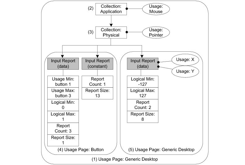
(1) The Usage Page item function specifies the general function of the device. In this example, the HID device belongs to a generic desktop control.
(2) The Collection Application groups Main items that have a common purpose and may be familiar to applications. In the diagram, the group is composed of three Input Main items. For this collection, the suggested use for the controls is a mouse as indicated by the Usage item.
(3) Nested collections may be used to give more details about the use of a single control or group of controls to applications. In this example, the Collection Physical, nested into the Collection Application, is composed of the same three Input items forming the Collection Application. The Collection Physical is used for a set of data items that represent data points collected at one geometric point. In the example, the suggested use is a pointer as indicated by the Usage item. Here the pointer usage refers to the mouse position coordinates and the system software will translate the mouse coordinates in movement of the screen cursor.
(4) Nested usage pages are also possible and give more details about a certain aspect within the general function of the device. In this case, two Inputs items are grouped and correspond to the buttons of the mouse. One Input item defines the three buttons of the mouse (right, left and wheel) in terms of number of data fields for the item (Report Count item), size of a data field (Report Size item) and possible values for each data field (Usage Minimum and Maximum, Logical Minimum and Maximum items). The other Input item is a 13-bit constant allowing the Input report data to be aligned on a byte boundary. This Input item is used only for padding purpose.
(5) Another nested usage page referring to a generic desktop control is defined for the mouse position coordinates. For this usage page, the Input item describes the data fields corresponding to the x- and y-axis as specified by the two Usage items.
After analyzing the previous mouse Report descriptor content, the host’s HID parser is able to interpret the Input report data sent by the device with an interrupt IN transfer or in response to a GET_REPORT request. The Input report data corresponding to the mouse Report descriptor shown in Figure - Report Descriptor Content from a Host HID Parser View in the USB Device HID Class Overview page is presented in Table - Input Report Sent to Host and Corresponding to the State of a 3-Buttons Mouse in the USB Device HID Class Overview page. The total size of the report data is 4 bytes. Different types of reports may be sent over the same endpoint. For the purpose of distinguishing the different types of reports, a 1-byte report ID prefix is added to the data report. If a report ID was used in the example of the mouse report, the total size of the report data would be 5 bytes.
Table - Input Report Sent to Host and Corresponding to the State of a 3-Buttons Mouse
Bit offset | Bit count | Description |
|---|---|---|
0 | 1 | Button 1 (left button). |
1 | 1 | Button 2 (right button). |
2 | 1 | Button 3 (wheel button). |
3 | 13 | Not used. |
16 | 8 | Position on axis X. |
24 | 8 | Position on axis Y. |
A Physical descriptor indicates the part or parts of the body intended to activate a control or controls. An application may use this information to assign a functionality to the control of a device. A Physical descriptor is an optional class-specific descriptor and most devices have little gain for using it. Refer to “Device Class Definition for Human Interface Devices (HID) Version 1.11” section 6.2.3 for more details about this descriptor.
USB Device HID Class Resource Needs from Core#
Each time you add a HID class instance to a USB configuration via a call to the function USBD_HID_ConfigAdd(), the following resources will be allocated from the core.
Resource | Quantity |
|---|---|
Interfaces | 1 |
Alternate interfaces | 1 |
Endpoint descriptors | 1 (2 if interrupt OUT endpoint is enabled) |
Interface groups | 0 |
USB Device HID Class Example Applications#
HID Class Mouse Example#
This example emulates a mouse moving back and forth.
This example will allow you to accomplish the following tasks:
Initialize the HID class
Create a HID class instance
Add the HID class instance to the Full-Speed configuration
Add the HID class instance to the High-Speed configuration (if available)
Create a kernel task that emulates the mouse movement
Running the Demo Application#
The mouse demo does not require anything extra on the PC. You just need to plug the HID device running the mouse demo to the PC and see the screen cursor moving.
Figure - HID Mouse Demo in the USB Device HID Class Example Applications page illustrates the mouse demo with the host and device interactions:
Figure - HID Mouse Demo#
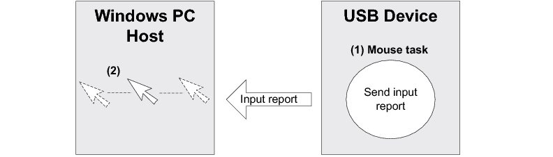
(1) On the device side, the task Ex_USBD_HID_MouseTask() simulates a mouse movement by setting the coordinates X and Y to a certain value and by sending an Input report that contains these coordinates. The Input report is sent by calling the USBD_HID_Wr() function through the interrupt IN endpoint. The mouse demo does not simulate any button clicks; only mouse movement.
(2) The host PC polls the HID device periodically following the polling interval of the interrupt IN endpoint. The polling interval is specified in the Endpoint descriptor matching to the interrupt IN endpoint. The host receives and interprets the Input report content. The simulated mouse movement is translated into a movement of the screen cursor. While the device side application is running, the screen cursor moves endlessly.
API#
This example makes use of only one API call named Ex_USBD_HID_Init(). This function is normally called from a USB device core example.
USB Device HID Class Configuration#
To configure the HID class, there are two groups of configuration parameters:
USB Device HID Class Run-Time Application Specific Configurations#
Class Initialization#
To initialize the Micrium OS USB Device HID class module, you call the USBD_HID_Init() function. This function takes one configuration argument which is described below.
p_qty_cfg#
p_qty_cfg is a pointer to a configuration structure of type USBD_HID_QTY_CFG. Its purpose is to inform the USB device module about how many USB HID objects to allocate.
Table - USBD_HID_QTY_CFG configuration structure in the USB Device HID Class Run-Time Application Specific Configurations page describes each configuration field available in this configuration structure.
Table - USBD_HID_QTY_CFG configuration structure#
Field | Description | Recommended Value |
|---|---|---|
.ClassInstanceQty | Number of class instances you will allocate via a call to the function USBD_HID_Add(). | 1 |
.ConfigQty | Number of configurations. HID class instances can be added to one or more configurations via a call to the function USBD_HID_ConfigAdd() . | 2 |
Optional Configurations#
This section describes the configurations that are optional. If you do not set them in your application, the default configurations will apply.
The default values can be retrieved via the structure USBD_HID_InitCfgDflt.
Note that these configurations must be set before you call the function USBD_HID_Init(). |
|---|
Buffer alignment#
This module allocates buffers used for data transfers with the host. You may need a specific address alignment for these buffers depending on your USB controller. If you use more than one USB controller, you must set the alignment to the highest value.
Type | Function to Call | Default | Field from Default Configuration Structure |
|---|---|---|---|
CPU_SIZE_T | USBD_HID_ConfigureBufAlignOctets() | Size of cache line, or CPU alignment, if no cache. | .BufAlignOctets |
Quantity of report ID#
Configures the total number of report IDs to allocate.
Type | Function to Call | Default | Field from Default Configuration Structure |
|---|---|---|---|
CPU_INT08U | USBD_HID_ConfigureReportID_Qty() | 2 | .ReportID_Qty |
Quantity of Push/Pop items#
Configures the total number of Push/Pop items to allocate.
Type | Function to Call | Default | Field from Default Configuration Structure |
|---|---|---|---|
CPU_INT08U | USBD_HID_ConfigurePushPopItemsQty() | 0 | .PushPopItemsQty |
Timer task stack#
The timer task handles all the timer-based HID operations. This configuration allows you to set the stack pointer and the stack size (in number of elements).
Type | Function to Call | Default | Field from Default Configuration Structure |
|---|---|---|---|
CPU_INT32U * | USBD_HID_ConfigureTmrTaskStk() | A stack of 512 elements allocated on Common 's memory segment. | .TmrTaskStkSizeElements |
void * | USBD_HID_ConfigureTmrTaskStk() | A stack of 512 elements allocated on Common 's memory segment. | .TmrTaskStkPtr |
Memory segments#
This module allocates control data and buffers used for data transfers with the host. It has the ability to use a different memory segment for the control data and for the data buffers.
Type | Function to Call | Default | Field from Default Configuration Structure |
|---|---|---|---|
MEM_SEG* | USBD_HID_ConfigureMemSeg() | .MemSegPtr | |
MEM_SEG* | USBD_HID_ConfigureMemSeg() | .MemSegBufPtr |
Post-Init Configurations#
This section describes the configurations that can be set at any time during execution after you have called the function USBD_HID_Init().
These configurations are optional. If you do not set them in your application, the default configurations will apply.
Timer task priority#
The timer task is created when the HID class is initialized. You can change the priority of the task at any time.
Type | Function to call | Default |
|---|---|---|
RTOS_TASK_PRIO | USBD_HID_TmrTaskPrioSet() |
USB Device HID Class Instance Configurations#
This section defines the configurations related to the HID class instances.
Class Instance Creation#
Creating a HID class instance is done by calling the function USBD_HID_Add() . This function takes several configuration arguments that are described below.
subclass#
Code of the HID subclass. Possible values are:
USBD_HID_SUBCLASS_NONE
USBD_HID_SUBCLASS_BOOT
A HID device that uses the boot subclass must use standard report formats. For more information on the subclass codes, see section 4.2 of HID specification revision 1.11.
protocol#
Protocol used by the HID device. Possible values are:
USBD_HID_PROTOCOL_NONE
USBD_HID_PROTOCOL_KBD
USBD_HID_PROTOCOL_MOUSE
If your HID function is a mouse, the protocol should be set to USBD_HID_PROTOCOL_MOUSE. If it is a keyboard, it should be set to USBD_HID_PROTOCOL_KBD . Otherwise, the protocol should be set to USBD_HID_PROTOCOL_NONE. For more information on the subclass codes, see section 4.3 of HID specification revision 1.11.
country_code#
ID of the country code. Possible values are:
USBD_HID_COUNTRY_CODE_NOT_SUPPORTED
USBD_HID_COUNTRY_CODE_ARABIC
USBD_HID_COUNTRY_CODE_BELGIAN
USBD_HID_COUNTRY_CODE_CANADIAN_BILINGUAL
USBD_HID_COUNTRY_CODE_CANADIAN_FRENCH
USBD_HID_COUNTRY_CODE_CZECH_REPUBLIC
USBD_HID_COUNTRY_CODE_DANISH
USBD_HID_COUNTRY_CODE_FINNISH
USBD_HID_COUNTRY_CODE_FRENCH
USBD_HID_COUNTRY_CODE_GERMAN
USBD_HID_COUNTRY_CODE_GREEK
USBD_HID_COUNTRY_CODE_HEBREW
USBD_HID_COUNTRY_CODE_HUNGARY
USBD_HID_COUNTRY_CODE_INTERNATIONAL
USBD_HID_COUNTRY_CODE_ITALIAN
USBD_HID_COUNTRY_CODE_JAPAN_KATAKANA
USBD_HID_COUNTRY_CODE_KOREAN
USBD_HID_COUNTRY_CODE_LATIN_AMERICAN
USBD_HID_COUNTRY_CODE_NETHERLANDS_DUTCH
USBD_HID_COUNTRY_CODE_NORWEGIAN
USBD_HID_COUNTRY_CODE_PERSIAN_FARSI
USBD_HID_COUNTRY_CODE_POLAND
USBD_HID_COUNTRY_CODE_PORTUGUESE
USBD_HID_COUNTRY_CODE_RUSSIA
USBD_HID_COUNTRY_CODE_SLOVAKIA
USBD_HID_COUNTRY_CODE_SPANISH
USBD_HID_COUNTRY_CODE_SWEDISH
USBD_HID_COUNTRY_CODE_SWISS_FRENCH
USBD_HID_COUNTRY_CODE_SWISS_GERMAN
USBD_HID_COUNTRY_CODE_SWITZERLAND
USBD_HID_COUNTRY_CODE_TAIWAN
USBD_HID_COUNTRY_CODE_TURKISH_Q
USBD_HID_COUNTRY_CODE_UK
USBD_HID_COUNTRY_CODE_US
USBD_HID_COUNTRY_CODE_YUGOSLAVIA
USBD_HID_COUNTRY_CODE_TURKISH_F
The country code identifies which country the hardware is localized for. Most hardware is not localized and therefore this value would be USBD_HID_COUNTRY_CODE_NOT_SUPPORTED (0). However, keyboards may use the field to indicate the language of the key caps.
For more information on the country codes, see section 6.2.1 of HID specification revision 1.11.
p_report_desc and report_desc_len#
p_report_desc is a pointer to a buffer that contains the report descriptor and report_desc_len is the length of the report descriptor buffer, in octets.
For each of your HID functions, you must provide a report descriptor. The report descriptor indicates to the host how the periodic report that will be sent by the device should be parsed. Writing your own report descriptor can be challenging, and that is why there are some resources to help.
HID Class Example#
Micrium's HID class application example provides an example of a report descriptor for a simple mouse. Listing - Mouse Report Descriptor Example in the USB Device HID Class Instance Configurations page shows the example mouse report descriptor.
Listing - Mouse Report Descriptor Example#
static CPU_INT08U App_USBD_HID_ReportDesc[] = { (1) (2)
USBD_HID_GLOBAL_USAGE_PAGE + 1, USBD_HID_USAGE_PAGE_GENERIC_DESKTOP_CONTROLS,
USBD_HID_LOCAL_USAGE + 1, USBD_HID_CA_MOUSE, (3)
USBD_HID_MAIN_COLLECTION + 1, USBD_HID_COLLECTION_APPLICATION, (4)
USBD_HID_LOCAL_USAGE + 1, USBD_HID_CP_POINTER, (5)
USBD_HID_MAIN_COLLECTION + 1, USBD_HID_COLLECTION_PHYSICAL, (6)
USBD_HID_GLOBAL_USAGE_PAGE + 1, USBD_HID_USAGE_PAGE_BUTTON, (7)
USBD_HID_LOCAL_USAGE_MIN + 1, 0x01,
USBD_HID_LOCAL_USAGE_MAX + 1, 0x03,
USBD_HID_GLOBAL_LOG_MIN + 1, 0x00,
USBD_HID_GLOBAL_LOG_MAX + 1, 0x01,
USBD_HID_GLOBAL_REPORT_COUNT + 1, 0x03,
USBD_HID_GLOBAL_REPORT_SIZE + 1, 0x01,
USBD_HID_MAIN_INPUT + 1, USBD_HID_MAIN_DATA |
USBD_HID_MAIN_VARIABLE |
USBD_HID_MAIN_ABSOLUTE,
USBD_HID_GLOBAL_REPORT_COUNT + 1, 0x01, (8)
USBD_HID_GLOBAL_REPORT_SIZE + 1, 0x0D,
USBD_HID_MAIN_INPUT + 1, USBD_HID_MAIN_CONSTANT,
(9)
USBD_HID_GLOBAL_USAGE_PAGE + 1, USBD_HID_USAGE_PAGE_GENERIC_DESKTOP_CONTROLS,
USBD_HID_LOCAL_USAGE + 1, USBD_HID_DV_X,
USBD_HID_LOCAL_USAGE + 1, USBD_HID_DV_Y,
USBD_HID_GLOBAL_LOG_MIN + 1, 0x81,
USBD_HID_GLOBAL_LOG_MAX + 1, 0x7F,
USBD_HID_GLOBAL_REPORT_SIZE + 1, 0x08,
USBD_HID_GLOBAL_REPORT_COUNT + 1, 0x02,
USBD_HID_MAIN_INPUT + 1, USBD_HID_MAIN_DATA |
USBD_HID_MAIN_VARIABLE |
USBD_HID_MAIN_RELATIVE,
USBD_HID_MAIN_ENDCOLLECTION, (10)
USBD_HID_MAIN_ENDCOLLECTION (11)
};(1) The table representing a mouse report descriptor is initialized in such way that each line corresponds to a short item. The latter is formed from a 1-byte prefix and a 1-byte data. Refer to “Device Class Definition for Human Interface Devices (HID) Version 1.11”, sections 5.3 and 6.2.2.2 for more details about short items format. This table content corresponds to the mouse report descriptor content viewed by a host HID parser in Figure - Report Descriptor Content from a Host HID Parser View in the USB Device HID Class Overview page.
(2) The Generic Desktop Usage Page is used.
(3) Within the Generic Desktop Usage Page, the usage tag suggests that the group of controls is for controlling a mouse. A mouse collection typically consists of two axes (X and Y) and one, two, or three buttons.
(4) The mouse collection is started.
(5) Within the mouse collection, a usage tag suggests more specifically that the mouse controls belong to the pointer collection. A pointer collection is a collection of axes that generates a value to direct, indicate, or point user intentions to an application.
(6) The pointer collection is started.
(7) The Buttons Usage Page defines an Input item composed of three 1-bit fields. Each 1-bit field represents the mouse’s button 1, 2 and 3 respectively and can return a value of 0 or 1.
(8) The Input Item for the Buttons Usage Page is padded with 13 other bits.
(9) Another Generic Desktop Usage Page is indicated for describing the mouse position with the axes X and Y. The Input item is composed of two 8-bit fields whose value can be between -127 and 127.
(10) The pointer collection is closed.
(11) The mouse collection is closed.
USB.org HID page#
The USB Implementers Forum (USB-IF) provides a tool called "HID Descriptor Tool" along with other information on the report descriptor format. Seehttp://www.usb.org/developers/hidpage/ for more information.
p_phy_desc and phy_desc_len#
p_phy_desc is a pointer to a buffer that contains the physical descriptor and phy_desc_len is the length of the physical descriptor buffer, in octets.
The physical descriptor is a descriptor that provides information about the specific part or parts of the human body that are activating a control or controls. For more information on physical descriptors, see section 6.2.3 of HID specification revision 1.11.
The physical descriptor is optional and most of the time ignored. The buffer passed here can be set to DEF_NULL and the length set to 0.
interval_in and interval_out#
interval_in and interval_out represent the polling interval of the IN interrupt endpoint and the OUT interrupt endpoint.
This represents the polling interval of the endpoint, in milliseconds. Setting this value depends on how frequently your device is susceptible to generate a new report for the host. For instance, if a report is generated every 16 milliseconds, the interval should be 16 or less.
The value must be a power of 2 (1, 2, 4, 8, 16, etc.).
interval_out value is ignored if ctrl_rd_en is set to DEF_ENABLED.
p_hid_callback#
p_hid_callback is a pointer to a structure of type USBD_HID_CALLBACK . Its purpose is to give the HID Class a set of optional callback functions to be called when a HID event occurs.
A null pointer (DEF_NULL) can be passed to this argument if no callbacks are needed.
Table Table - USBD_HID_CALLBACK configuration structure in the USB Device HID Class Instance Configurations page describes each configuration field available in this configuration structure.
Table - USBD_HID_CALLBACK configuration structure#
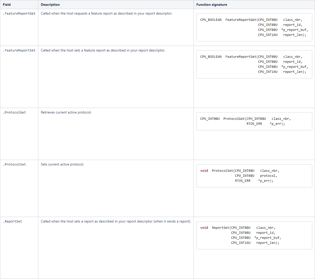
USB Device HID Class Programming Guide#
This section explains how to use the HID class.
Initializing the USB Device HID Class#
To add HID Class functionality to your device, you must first initialize the class by calling the function USBD_HID_Init().
Listing - Example of call to USBD_HID_Init() in the Initializing the USB Device HID Class page shows an example of a call to USBD_HID_Init() using default arguments. For more information on the configuration arguments to pass to USBD_HID_Init(), see USB Device HID Class Run-Time Application Specific Configurations .
Listing - Example of call to USBD_HID_Init()#
RTOS_ERR err;
USBD_HID_QTY_CFG hid_qty_cfg;
hid_qty_cfg.ClassInstanceQty = 1u;
hid_qty_cfg.ConfigQty = 2u;
USBD_HID_Init(&hid_qty_cfg,
&err);
if (err.Code != RTOS_ERR_NONE) {
/* An error occured. Error handling should be added here. */
}Adding a USB Device HID Class Instance to your Device#
To add HID class functionality to your device, you must create an instance, then add it to your device's configuration(s).
Creating a HID class Instance#
Create a HID class instance by calling the function USBD_HID_Add().
Listing - Adding a mouse function via USBD_HID_Add() in the Adding a USB Device HID Class Instance to your Device page shows an example of how to create a simple mouse function via USBD_HID_Add() using default arguments. For more information on the configuration arguments to pass to USBD_HID_Add(), see USB Device HID Class Instance Configurations .
Listing - Adding a mouse function via USBD_HID_Add()#
/* Global constants. */
static const CPU_INT08U Ex_USBD_HID_Mouse_ReportDesc[] = {
USBD_HID_GLOBAL_USAGE_PAGE + 1, USBD_HID_USAGE_PAGE_GENERIC_DESKTOP_CONTROLS,
USBD_HID_LOCAL_USAGE + 1, USBD_HID_CA_MOUSE,
USBD_HID_MAIN_COLLECTION + 1, USBD_HID_COLLECTION_APPLICATION,
USBD_HID_LOCAL_USAGE + 1, USBD_HID_CP_POINTER,
USBD_HID_MAIN_COLLECTION + 1, USBD_HID_COLLECTION_PHYSICAL,
USBD_HID_GLOBAL_USAGE_PAGE + 1, USBD_HID_USAGE_PAGE_BUTTON,
USBD_HID_LOCAL_USAGE_MIN + 1, 0x01,
USBD_HID_LOCAL_USAGE_MAX + 1, 0x03,
USBD_HID_GLOBAL_LOG_MIN + 1, 0x00,
USBD_HID_GLOBAL_LOG_MAX + 1, 0x01,
USBD_HID_GLOBAL_REPORT_COUNT + 1, 0x03,
USBD_HID_GLOBAL_REPORT_SIZE + 1, 0x01,
USBD_HID_MAIN_INPUT + 1, USBD_HID_MAIN_DATA | USBD_HID_MAIN_VARIABLE | USBD_HID_MAIN_ABSOLUTE,
USBD_HID_GLOBAL_REPORT_COUNT + 1, 0x01,
USBD_HID_GLOBAL_REPORT_SIZE + 1, 0x0D,
USBD_HID_MAIN_INPUT + 1, USBD_HID_MAIN_CONSTANT,
USBD_HID_GLOBAL_USAGE_PAGE + 1, USBD_HID_USAGE_PAGE_GENERIC_DESKTOP_CONTROLS,
USBD_HID_LOCAL_USAGE + 1, USBD_HID_DV_X,
USBD_HID_LOCAL_USAGE + 1, USBD_HID_DV_Y,
USBD_HID_GLOBAL_LOG_MIN + 1, 0x81,
USBD_HID_GLOBAL_LOG_MAX + 1, 0x7F,
USBD_HID_GLOBAL_REPORT_SIZE + 1, 0x08,
USBD_HID_GLOBAL_REPORT_COUNT + 1, 0x02,
USBD_HID_MAIN_INPUT + 1, USBD_HID_MAIN_DATA | USBD_HID_MAIN_VARIABLE | USBD_HID_MAIN_RELATIVE,
USBD_HID_MAIN_ENDCOLLECTION,
USBD_HID_MAIN_ENDCOLLECTION
};
/* Local variables.*/
CPU_INT08U class_nbr;
RTOS_ERR err;
class_nbr = USBD_HID_Add(USBD_HID_SUBCLASS_BOOT,
USBD_HID_PROTOCOL_MOUSE,
USBD_HID_COUNTRY_CODE_NOT_SUPPORTED,
Ex_USBD_HID_Mouse_ReportDesc,
sizeof(Ex_USBD_HID_Mouse_ReportDesc),
DEF_NULL,
0u,
2u,
2u,
DEF_YES,
DEF_NULL,
&err);
if (err.Code != RTOS_ERR_NONE) {
/* An error occurred. Error handling should be added here. */
}Adding the HID Class Instance to Your Device's Configuration(s)#
Once you have created a HID class instance, you can add it to a configuration by calling the function USBD_HID_ConfigAdd().
Listing - Example of call to USBD_HID_ConfigAdd() in the Adding a USB Device HID Class Instance to your Device page shows an example of a call to USBD_HID_ConfigAdd().
Listing - Example of call to USBD HID ConfigAdd()#
RTOS_ERR err;
USBD_HID_ConfigAdd(class_nbr, (1)
dev_nbr, (2)
config_nbr_fs, (3)
&err);
if (err.Code != RTOS_ERR_NONE) {
/* An error occurred. Error handling should be added here. */
}
USBD_HID_ConfigAdd(class_nbr, (4)
dev_nbr,
config_nbr_hs,
&err);
if (err.Code != RTOS_ERR_NONE) {
/* An error occurred. Error handling should be added here. */
}(1) Class number to add to the configuration returned by USBD_HID_Add().
(2) Device number returned by USBD_DevAdd().
(3) Configuration number (here adding it to a Full-Speed configuration).
(4) Adding the same class instance to the High-Speed configuration. This should be done only if you have a High-Speed device.
Communicating using the USB Device HID Class#
Class Instance Communication#
The HID class offers the following functions to communicate with the host.
Table - HID Communication API Summary#
Function name | Operation |
|---|---|
USBD_HID_Rd() | Receives data from the host through interrupt OUT endpoint. This function is blocking. |
USBD_HID_Wr() | Sends data to the host through interrupt IN endpoint. This function is blocking. |
Synchronous Communication#
Synchronous communication means that the transfer is blocking. Upon the function call, the applications blocks until the transfer is completed with or without an error. A timeout can be specified to avoid waiting forever.
Listing - Synchronous HID Read and Write Example in the Communicating using the USB Device HID Class page shows a read and write example that receives data from the host using the interrupt OUT endpoint and sends data to the host using the interrupt IN endpoint.
Listing - Synchronous HID Read and Write Example#
CPU_INT08U rx_buf[2];
CPU_INT08U tx_buf[2];
RTOS_ERR err;
(void)USBD_HID_Rd( class_nbr, (1)
(void *)rx_buf, (2)
2u,
0u, (3)
&err);
if (err.Code != RTOS_ERR_NONE) {
/* An error occurred. Error handling should be added here. */
}
(void)USBD_HID_Wr( class_nbr, (1)
(void *)tx_buf, (4)
2u,
0u, (3)
&err);
if (err.Code != RTOS_ERR_NONE) {
/* An error occurred. Error handling should be added here. */
}(1) The class instance number created from USBD_HID_Add() provides an internal reference for the HID class to route the transfer to the proper interrupt OUT or IN endpoint.
(2) The application must ensure that the buffer provided to the function is large enough to accommodate all the data. Otherwise, synchronization issues might happen. Internally, the read operation is done either with the control endpoint or with the interrupt endpoint, depending on the control read flag set when calling USBD_HID_Add().
(3) To avoid an infinite blocking situation, a timeout expressed in milliseconds can be specified. A value of ‘0’ makes the application task wait forever.
(4) The application provides the initialized transmit buffer.
HID Periodic Input Reports Task#
To save bandwidth, the host has the ability to silence reports from an interrupt IN endpoint by limiting the reporting frequency. To do so, the host must send the SET_IDLE request. The HID class implemented by Micrium contains an internal task that respects the reporting frequency limitation that you can apply to one or several input reports. Figure - Periodic Input Reports Task in the HID Periodic Input Reports Task page shows the functioning of the periodic input reports tasks.
Figure - Periodic Input Reports Task#
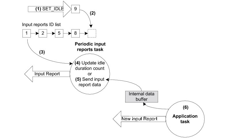
(1) The device receives a SET_IDLE request. This request specifies an idle duration for a given report ID. For more details about the SET_IDLE request, refer to “Device Class Definition for Human Interface Devices (HID) Version 1.11”, section 7.2.4. A report ID allows you to distinguish among the different types of reports sent from the same endpoint.
(2) A report ID structure (allocated during the HID class initialization phase) is updated with the idle duration. An idle duration counter is initialized with the idle duration value. The report ID structure is inserted at the end of a linked list containing input reports ID structures. The idle duration value is expressed in 4-ms unit which gives a range of 4 to 1020 ms. If the idle duration is less than the polling interval of the interrupt IN endpoint, the reports are generated at the polling interval.
(3) Every 4 ms, the periodic input report task browses the input reports ID list. For each input report ID, the task performs one of two possible operations. The duration of the task period matches the 4-ms unit used for the idle duration. If no SET_IDLE requests have been sent by the host, the input reports ID list is empty and the task has nothing to process. The task processes only report IDs that are different from 0 and with an idle duration greater than 0.
(4) For a given input report ID, the task verifies if the idle duration has elapsed. If the idle duration has not elapsed, the counter is decremented and no input report is sent to the host.
(5) If the idle duration has elapsed (that is, the idle duration counter has reached zero), an input report is sent to the host by calling the USBD_HID_Wr() function via the interrupt IN endpoint.
(6) The input report data sent by the task comes from an internal data buffer allocated for each input report described in the Report descriptor. An application task can call the USBD_HID_Wr() function to send an input report. After sending the input report data, USBD_HID_Wr() updates the internal buffer associated to an input report ID with the data just sent. Then, the periodic input reports task always sends the same input report data after each idle duration elapsed and until the application task updates the data in the internal buffer. There is some locking mechanism to avoid corruption of the input report ID data in the event of a modification happening at the exact time of transmission done by the periodic input report task.
USB Device MSC Class#
This section describes the mass storage device class (MSC) supported by Micrium OS USB Device. MSC is a protocol that enables the transfer of information between a USB device and a host. The information being transferred is anything that can be stored electronically: executable programs, source code, documents, images, configuration data, or other text or numeric data. The USB device appears as an external storage medium to the host, enabling the transfer of files via drag and drop.
A file system defines how the files are organized in the storage media. The USB mass storage class specification does not require any particular file system to be used on conforming devices. Instead, it provides a simple interface to read and write sectors of data using the Small Computer System Interface (SCSI) transparent command set. As such, operating systems may treat the USB drive like a hard drive, and can format it with any file system they like.
The USB mass storage device class supports two transport protocols:
Bulk-Only Transport (BOT)
Control/Bulk/Interrupt (CBI) Transport (used only for floppy disk drives)
The mass storage device class implements the SCSI transparent command set using the BOT protocol only, which signifies that only bulk endpoints will be used to transmit data and status information. The MSC implementation supports multiple logical units.
The MSC implementation is in compliance with the following specifications:
Universal Serial Bus Mass Storage Class Specification Overview, Revision 1.3 Sept. 5, 2008.
Universal Serial Bus Mass Storage Class Bulk-Only Transport, Revision 1.0 Sept. 31, 1999.
USB Device MSC Class Overview#
Protocol#
In this section, we will discuss the Bulk-Only Transport (BOT) protocol of the Mass Storage Class. The Bulk-Only Transport protocol has three stages:
The Command Transport
The Data Transport
The Status Transport
Mass storage commands are sent by the host through a structure called the Command Block Wrapper (CBW). For commands requiring a data transport stage, the host will attempt to send or receive the exact number of bytes from the device as specified by the length and flag fields of the CBW. After the data transport stage, the host attempts to receive a Command Status Wrapper (CSW) from the device that details the status of the command as well as any data residue (if any). For commands that do not include a data transport stage, the host attempts to receive the CSW directly after CBW is sent. The protocol is detailed in Figure - MSC Protocol in the USB Device MSC Class Overview page.
Figure - MSC Protocol#
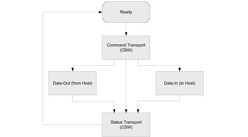
Endpoints#
On the device side, in compliance with the BOT specification, the MSC is composed of the following endpoints:
A pair of control IN and OUT endpoints called default endpoint.
A pair of bulk IN and OUT endpoints.
Table - MSC Endpoint Usage in the USB Device MSC Class Overview page indicates the different usages of the endpoints.
Table - MSC Endpoint Usage#
Endpoint | Direction | Usage |
|---|---|---|
Control IN | Device to Host | Enumeration and MSC class-specific requests |
Control OUT | Host to Device | Enumeration and MSC class-specific requests |
Bulk IN | Device to Host | Send CSW and data |
Bulk OUT | Host to Device | Receive CBW and data |
Class Requests#
There are two defined control requests for the MSC BOT protocol. These requests and their descriptions are detailed in Table - Mass Storage Class Requests in the USB Device MSC Class Overview page.
Table - Mass Storage Class Requests#
Class Requests | Description |
|---|---|
Bulk-Only Mass Storage Reset | This request is used to reset the mass storage device and its associated interface. This request readies the device to receive the next command block. |
Get Max LUN | This request is used to return the highest logical unit number (LUN) supported by the device. For example, a device with LUN 0 and LUN 1 will return a value of 1. A device with a single logical unit will return 0 or stall the request. The maximum value that can be returned is 15. |
Small Computer System Interface (SCSI)#
SCSI is a set of standards for handling communication between computers and peripheral devices. These standards include commands, protocols, electrical interfaces and optical interfaces. Storage devices that use other hardware interfaces, such as USB, use SCSI commands for obtaining device/host information and controlling the device’s operation and transferring blocks of data in the storage media.
SCSI commands cover a vast range of device types and functions and as such, devices need a subset of these commands. In general, the following commands are necessary for basic communication:
INQUIRY
READ CAPACITY(10)
READ(10)
REQUEST SENSE
TEST UNIT READY
WRITE(10)
USB Device MSC Class Resource Needs from Core#
Each time you add an MSC class instance to a USB configuration via the function USBD_MSC_ConfigAdd(), the following resources will be allocated from the core.
Resource | Quantity |
|---|---|
Interfaces | 1 |
Alternate interfaces | 1 |
Endpoint descriptors | 2 |
Interface groups | 0 |
USB Device MSC Class Example Applications#
MSC Class Ramdisk LUN Example#
This example creates a simple MSC function with a single Logical Unit using a RAM disk as a storage medium. It requires the presence of Micrium OS FS in your project, and assumes that the Block Device module is initialized .
This example will allow you to accomplish the following tasks:
Create a RAM disk media named "ramusb"
Initialize the MSC class
Create a MSC class instance
Add a logical unit to the MSC class instance
Add the MSC class instance to the Full-Speed configuration
Add the MSC class instance to the High-Speed configuration (if available)
Attach the "ramusb" storage media to the logical unit
Location#
The example implementation is located in /examples/usb/device/all/ex_usbd_msc_ramdisk_lun.c.
Running the Demo Application#
Once you connect the device to a Windows host PC (and once the drivers are installed), you should see a new drive available that represents your USB flash drive. Since it uses a RAM disk, you will have to format the drive each time the target is power cycled.
You can then create files/folders, read them, etc.
API#
This example offers only one API named Ex_USBD_MSC_Init(). This function is normally called from a USB device core example.
MSC Class Ramdisk Shared Example
This example creates a simple MSC function with a single Logical Unit using a RAM disk as a storage medium. Its purpose is to demonstrate how a storage media can be shared between a USB host and your embedded application. It requires the presence of Micrium OS FS in your project and assumes that the Block Device module is initialized .
This example will allow you to accomplish the following tasks:
Create and configure a RAMDisk media named "ramusb"
Initialize the MSC class
Create a MSC class instance
Add a logical unit to the MSC class instance
Add the MSC class instance to the Full-Speed configuration
Add the MSC class instance to the High-Speed configuration (if available)
Create a kernel task that will handle the application that shares the media with the host.
Location#
The example implementation is located in /examples/usb/device/all/ex_usbd_msc_ramdisk_shared.c.
Running the Demo Application#
This application is executed within the task body implemented in the function Ex_USBD_MSC_Task(). Within a loop, the application executes the following steps:
Open the volume present on the RAM disk storage device using the Micrium OS FS API
Create/Open a file named "Embedded.txt"
Add the string "Iteration number <X>" to the file content (where <X> represents the number of the iteration)
Close the file, volume and device
Attach the RAM disk device to the MSC class instance logical unit. From this point, the media is visible from the host side
Wait five seconds
Detach the RAM disk device from the MSC class instance logical unit. From this point, the media appears as unavailable from the host side
The loop executes for 10 iterations. After the 10 iterations, the RAMDisk device remains attached to the logical unit.
API#
This example offers only one API named Ex_USBD_MSC_Init(). This function is normally called from a USB device core example.
USB Device MSC Class Configuration#
To configure the MSC class, there are three groups of configuration parameters:
USB Device MSC Class Compile-Time Configurations#
Micrium OS USB Device MSC class is configurable at compile time via one #define located in the usbd_cfg.h file.
We recommend that you begin the configuration process with the default configuration values, which are shown in bold.
Table - Generic Configuration Constants#
Constant | Description | Possible values |
|---|---|---|
USBD_SCSI_CFG_64_BIT_LBA_EN | Enables or disables support for Logical Block Address (LBA) of 64 bits. | DEF_ENABLED or DEF_DISABLED |
USB Device MSC Class Run-time Application Specific Configurations#
Class Initialization#
Initializing the USB Device MSC class module of Micrium OS is done by calling the USBD_MSC_Init() function. This function takes one configuration argument which is described below.
p_qty_cfg#
p_qty_cfg is a pointer to a configuration structure of type USBD_MSC_QTY_CFG. Its purpose is to inform the USB device MSC module on how many USB MSC objects to allocate.
Table - USBD_MSC_QTY_CFG configuration structure in the USB Device MSC Class Run-time Application Specific Configurations page describes each configuration field available in this configuration structure.
Table - USBD_MSC_QTY_CFG configuration structure#
Field | Description | Recommended value |
|---|---|---|
.ClassInstanceQty | Number of class instances you will allocate via a call to the function USBD_MSC_Add(). | 1 |
.ConfigQty | Number of configuration to which a class instance can be added via a call to the function USBD_MSC_ConfigAdd(). | 2 |
.LUN_Qty | Number of logical units per class instance that you will add via a call to the function USBD_MSC_SCSI_LunAdd(). | 1 |
Optional Configurations#
This section describes the configurations that are optional. If you do not set them in your application, the default configurations will apply.
The default values can be retrieved via the structure USBD_MSC_InitCfgDflt.
Note: These configurations must be set before you call the function USBD_MSC_Init(). |
|---|
Configurations | Description | Type | Function to call | Default | Field from default configuration structure |
|---|---|---|---|---|---|
Buffer alignment | This module allocates some buffers used for data transfers with the host. You may need a specific address alignment for these buffers depending on your USB controller. If you use more than one USB controller, you must set the alignment to the highest value. | CPU_SIZE_T | USBD_MSC_ConfigureBufAlignOctets() | Size of cache line, or CPU alignment, if no cache. | .BufAlignOctets |
Data buffer length | Configures the length of the MSC data buffer, in octets. | CPU_INT32U | USBD_MSC_ConfigureDataBufLen() | 512 octets | .DataBufLen |
Memory segments | This module allocates some control data and buffers used for data transfers with the host. It has the ability to use a different memory segment for the control data and for the data buffers. | MEM_SEG* | USBD_MSC_ConfigureMemSeg() | .MemSegPtr | |
Memory segments | This module allocates some control data and buffers used for data transfers with the host. It has the ability to use a different memory segment for the control data and for the data buffers. | MEM_SEG* | USBD_MSC_ConfigureMemSeg() | .MemSegBufPtr |
Table - MSC Class Optional Configurations
Post-Init Configurations#
This section describes the configurations that can be set at any time during execution after you called the function USBD_MSC_Init().
These configurations are optional. If you do not set them in your application, the default configurations will apply.
Configurations | Description | Type | Function to call | Default |
|---|---|---|---|---|
MSC instance task priority | Each MSC class instance created via the function USBD_MSC_Add() will create a task. You can change the priority of the created task at any time. | RTOS_TASK_PRIO | USBD_MSC_TaskPrioSet() | N/A |
Table - MSC Class Post-init Configurations
Class Instance Creation#
Creating a USB Device MSC class instance is done by calling the USBD_MSC_Add() function. This function takes one configuration argument that is described below.
p_msc_task_cfg#
p_msc_task_cfg is a pointer to a configuration structure of type RTOS_TASK_CFG that allows you to configure the priority, stack base pointer and stack size for the MSC instance task. This task handles all the MSC request and data transfers.
USB Device MSC Class Logical Unit Configuration#
Adding a logical unit to an MSC class instance is done by calling the function USBD_MSC_SCSI_LunAdd() . This function takes two configuration arguments that are described below.
p_lu_fncts#
p_lu_fncts is a pointer to a structure of type USBD_SCSI_LU_FNCTS. Its purpose is to provide the MSC class with a set of optional callback functions that are called when an event occurs on the logical unit.
A null pointer (DEF_NULL) can be passed to this argument if no callbacks are needed.
Table - USBD_SCSI_LU_FNCTS configuration structure in the USB Device MSC Class Logical Unit Configuration page describes each configuration field available in this configuration structure.
Table - USBD_SCSI_LU_FNCTS configuration structure#
Field | Description | Function signature |
|---|---|---|
.HostEjectEvent | Function called when a logical unit is ejected from the host. | void HostEjectEvent(CPU_INT08U lu_nbr); |
p_lu_info#
p_lu_info is a pointer to a structure of type USBD_SCSI_LU_INFO. Its purpose is to provide the information on the logical unit to the MSC class.
Table - USBD_SCSI_LU_INFO configuration structure in the USB Device MSC Class Logical Unit Configuration page describes each configuration field available in this configuration structure.
Table - USBD_SCSI_LU_INFO configuration structure#
Field | Description |
|---|---|
.SCSI_StorageAPI_Ptr | Pointer to the media driver API that will handle this logical unit. See USB Device MSC Class Storage Drivers for more information on storage drivers. |
.VendIdPtr | Pointer to a string that contains the vendor identification of the logical unit. The maximum length of the string is 8 characters. |
.ProdIdPtr | Pointer to a string that contains the product identification of the logical unit. The maximum length of the string is 16 characters. |
.ProdRevLevel | Product revision level. |
.IsRdOnly | Flag that indicates if the logical unit should be seen as read only from the point of view of the host (DEF_YES) or not (DEF_NO). |
USB Device MSC Class Programming Guide#
This section explains how to use the MSC class.
Initializing the USB Device MSC Class#
To add MSC Class functionality to your device, you must first initialize the class by calling the function USBD_MSC_Init().
Listing - Example of call to USBD_MSC_Init() in the Initializing the USB Device MSC Class page shows an example of call to USBD_MSC_Init() using default arguments. For more information on the configuration arguments to pass to USBD_MSC_Init(), see USB Device MSC Class Run-time Application Specific Configurations .
Listing - Example of call to USBD_MSC_Init()#
RTOS_ERR err;
USBD_MSC_QTY_CFG msc_qty_cfg;
msc_qty_cfg.ClassInstanceQty = 1u;
msc_qty_cfg.ConfigQty = 2u;
msc_qty_cfg.LUN_Qty = 1u;
USBD_MSC_Init(&msc_qty_cfg,
&err);
if (err.Code != RTOS_ERR_NONE) {
/* An error occurred. Error handling should be added here. */
}Adding a USB Device MSC Class Instance to your Device#
To add MSC class functionality to your device, you must first create an instance, then add it to your device's configuration(s). You must add at least one logical unit to your instance.
Creating an MSC Class Instance#
Create a MSC class instance by calling the function USBD_MSC_Add().
Listing - Example of call to USBD_MSC_Add() in the Adding a USB Device MSC Class Instance to your Device page gives an example of call to USBD_MSC_Add() using default arguments. For more information on the configuration arguments to pass to USBD_MSC_Add(), see USB Device MSC Class Run-time Application Specific Configurations .
Listing - Example of call to USBD_MSC_Add()#
CPU_INT08U class_nbr;
RTOS_TASK_CFG msc_task_cfg;
RTOS_ERR err;
msc_task_cfg.Prio = 20u;
msc_task_cfg.StkSizeElements = 512u;
msc_task_cfg.StkPtr = DEF_NULL;
class_nbr = USBD_MSC_Add(&msc_task_cfg
&err);
if (err.Code != RTOS_ERR_NONE) {
/* An error occurred. Error handling should be added here. */
}Adding the MSC Class Instance to Your Device's Configuration(s)#
Once you have created an MSC class instance, you can add it to a configuration by calling the function USBD_MSC_ConfigAdd().
Listing - Example of call to USBD_MSC_ConfigAdd() in the Adding a USB Device MSC Class Instance to your Device page shows an example of call to USBD_MSC_ConfigAdd() using default arguments.
Listing - Example of call to USBD_MSC_ConfigAdd()#
RTOS_ERR err;
USBD_MSC_ConfigAdd(class_nbr, (1)
dev_nbr, (2)
config_nbr_fs, (3)
&err);
if (err.Code != RTOS_ERR_NONE) {
/* An error occurred. Error handling should be added here. */
}
USBD_MSC_ConfigAdd(class_nbr, (4)
dev_nbr,
config_nbr_hs,
&err);
if (err.Code != RTOS_ERR_NONE) {
/* An error occurred. Error handling should be added here. */
}(1) Class number to add to the configuration returned by USBD_MSC_Add().
(2) Device number returned by USBD_DevAdd().
(3) Configuration number (here adding it to a Full-Speed configuration).
(4) Adding the same class instance to the High-Speed configuration. This should be done only if you have a High-Speed device.
USB Device MSC Class Logical Unit Handling#
Adding a Logical Unit#
When adding a logical unit to your MSC class instance, it must be bound to a storage medium (RAMDisk, SD card, Flash memory, etc). The MSC class uses a storage driver to communicate with storage media.
Even though you could create your own storage media driver, Micrium recommends the use of the universal block device driver. This driver allows you to use any type of storage media (RAMDisk, SD, NOR, NAND, etc) that are supported by the block device API of Micrium OS FS.
This driver also allows you to use the driver with or without Micrium OS FS available in your project.
Listing - Adding a logical unit via USBD_MSC_SCSI_LunAdd() in the USB Device MSC Class Logical Unit Handling page shows an example of adding a logical unit via USBD_MSC_SCSI_LunAdd().
Listing - Adding a logical unit via USBD_MSC_SCSI_LunAdd()#
CPU_INT08U lu_nbr;
USBD_SCSI_LU_INFO lu_info;
RTOS_ERR err;
lu_info.SCSI_StorageAPI_Ptr = &USBD_SCSI_StorageBlkDevAPI; (1)
lu_info.VendIdPtr = "Micrium";
lu_info.ProdIdPtr = "FS example";
lu_info.ProdRevLevel = 0x1000u;
lu_info.IsRdOnly = DEF_NO;
lu_nbr = USBD_MSC_SCSI_LunAdd(class_nbr,
&lu_info,
DEF_NULL,
&err);
if (err.Code != RTOS_ERR_NONE) {
/* An error occurred. Error handling should be added here. */
}Attaching/Detaching a Storage Medium#
Once the logical unit has been added, a storage medium must be attached to it in order to be available from the host side.
The MSC class offers two functions to control the storage media association to the logical unit: USBD_MSC_SCSI_LunAttach() and USBD_MSC_SCSI_LunDetach(). These functions allow you to emulate the removal of a storage device in order to re-gain access from the embedded application if necessary.
Listing - Example of Media Attach/Detach in the USB Device MSC Class Logical Unit Handling page shows an example of how to use the function USBD_MSC_SCSI_LunAttach() and USBD_MSC_SCSI_LunDetach().
Listing - Example of Media Attach/Detach#
RTOS_ERR err;
USBD_MSC_SCSI_LunAttach(class_nbr,
lu_nbr,
media_name, (1)
&err)
if (err.Code != RTOS_ERR_NONE) {
/* An error occurred. Error handling should be added here. */
}
... (2)
USBD_MSC_SCSI_LunDetach(class_nbr,
lu_nbr,
&err)
if (err.Code != RTOS_ERR_NONE) {
/* An error occurred. Error handling should be added here. */
}
... (3)
USBD_MSC_SCSI_LunAttach(class_nbr,
lu_nbr,
media_name, (4)
&err)
if (err.Code != RTOS_ERR_NONE) {
/* An error occurred. Error handling should be added here. */
}
... (5)(1) Here we pass a string to the block device media that we want to use as storage. This string id is associated to a storage device that must have been registered to the platform manager previously.
(2) From this moment, if the MSC device is connected to a host, the storage media is accessible.
(3) If the MSC device is connected to a host, the media will now appear as unavailable. At this moment, operations can be performed on the media from the embedded application using Micrium OS FS API.
(4) Again, we pass a string to the block device media that we want to use as storage. It can technically be another storage medium than in (1), even though it is the same logical unit.
(5) Again, if the MSC device is connected to the host, the storage media will appear as connected.
USB Device MSC Class Storage Drivers#
The USB Device MSC Class needs a storage driver to communicate with a storage medium. For the moment, Micrium offers only one driver.
Universal Block Device Driver#
The universal block device driver allows you to use any storage media (RAMDisk, SD card, NAND, NOR, etc.) that are supported by the Block Device module.
This driver also allows the same media to be accessed from your embedded application via the Micrium OS FS API.
Table - Universal Block Device Driver Description in the USB Device MSC Class Storage Drivers page provides a description of this driver.
Table - Universal Block Device Driver Description#
Name | Universal Block Device |
|---|---|
Storage API structure name | USBD_SCSI_StorageBlkDevAPI located in usbd_scsi_storage_blk_dev.h |
USB Device Vendor Class#
The Vendor class allows you to build vendor-specific devices that can implement a proprietary protocol. It relies on a pair of bulk endpoints to transfer data between the host and the device. Bulk transfers are convenient for transferring large amounts of unstructured data and provide a reliable exchange of data by using an error detection and retry mechanism.
In addition to bulk endpoints, the Vendor class can also use an optional pair of interrupt endpoints. Any operating system (OS) can work with the Vendor class provided that the OS has a driver to handle the Vendor class. Depending on the OS, the driver can be native or vendor-specific. For instance, under Microsoft Windows®, your application interacts with the WinUSB driver provided by Microsoft to communicate with the vendor device.
USB Device Vendor Class Overview#
Figure - General Architecture Between Windows Host and Vendor Class in the USB Device Vendor Class Overview page shows the general architecture between the host and the device using the Vendor class. In this example, the host operating system is MS Windows.
Figure - General Architecture Between MS Windows Host and Vendor Class#
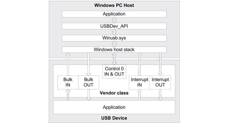
On the MS Windows side, the application communicates with the vendor device by interacting with the USBDev_API library. This library, provided by Micrium, offers an API to manage a device and its associated pipes, and to communicate with the device through control, bulk and interrupt endpoints. USBDev_API is a wrapper that allows the use of the WinUSB functions exposed by Winusb.dll.
On the device side, the Vendor class is composed of the following endpoints:
A pair of control IN and OUT endpoints called the default endpoint.
A pair of bulk IN and OUT endpoints.
A pair of interrupt IN and OUT endpoints. This pair is optional.
Table - Vendor Class Endpoints Usage in the USB Device Vendor Class Overview page indicates the usage of the different endpoints:
Table - Vendor Class Endpoints Usage#
Endpoint | Direction | Usage |
|---|---|---|
Control IN | Device-to-host | Standard requests for enumeration and vendor-specific requests. |
Control OUT | >Host-to-device | Standard requests for enumeration and vendor-specific requests. |
Bulk IN | Device-to-host | Raw data communication. Data can be structured according to a proprietary protocol. |
Bulk OUT | Host-to-device | Raw data communication. Data can be structured according to a proprietary protocol. |
Interrupt IN | Device-to-host | Raw data communication or notification. Data can be structured according to a proprietary protocol. |
Interrupt OUT | Host-to-device | Raw data communication or notification. Data can be structured according to a proprietary protocol. |
The device application can use bulk and interrupt endpoints to send or receive data to or from the host. It can only use the default endpoint to decode vendor-specific requests sent by the host. The standard requests are managed internally by the Core layer of Micrium OS USB Device.
USB Device Vendor Class Resource Needs from Core#
Each time you add a vendor class instance to a configuration via the function USBD_Vendor_ConfigAdd(), the following resources will be allocated from the core.
Resource | Quantity |
|---|---|
Interfaces | 1 |
Alternate interfaces | 1 |
Endpoint descriptors | 2 (4 if you enabled interrupt endpoints) |
Interface groups | 0 |
USB Device Vendor Class Example Applications#
Vendor Class Loopback Example#
This simple example receives data from a host and re-transmits it, hence creating a loopback. It offers two implementations: one that uses the synchronous API, and another one that uses the asynchronous API. Both implementations can be enabled at the same time, therefore creating a composite device.
This example will allow you to accomplish the following tasks:
Initialize the Vendor class
Create a Vendor class instance
Add the Vendor class instance to the Full-Speed configuration
Add the Vendor class instance to the High-Speed configuration (if available)
Set the Microsoft Extended Property to specify the GUID
Create a kernel task that implements the loopback (one task for the synchronous implementation and/or one task for the asynchronous implementation)
Location#
The example implementation is located in /examples/usb/device/all/ex_usbd_vendor_loopback.c.
To execute it, you will also need some files on the host side. The files can be downloaded from the Micrium web site .
To install the Windows driver for the device (only if you do not use the Microsoft OS Descriptors), use the .inf file from the Windows application files located in micrium_usb_dev_host_app/OS/Windows/Vendor/INF.
To execute the example application, you will also require a custom executable application on the host side. These files are located in micrium_usb_dev_host_app/OS/Windows/Vendor/Visual Studio 2010/exe/x86.
Configuration#
There are two #defines available in the file ex_usbd_vendor_loopback.c, which are used to select the synchronous and/or asynchronous implementation:
EX_USBD_VENDOR_LOOPBACK_CFG_SYNC_EN
EX_USBD_VENDOR_LOOPBACK_CFG_SYNC_EN
They must be set to either DEF_ENABLED to enable the implementation or DEF_DISABLED to disable the implementation. At least one of the #defines should be enabled at any time. Both can be enabled at the same time.
Running the Demo Application#
The application used to demonstrate Vendor class communication between the host and the device is called the Echo demo. This demo implements a simple protocol allowing the device to echo the data sent by the host.
There are two varieties of the Echo demo. The Echo Sync application demonstrates the synchronous communication API, and the Echo Async application demonstrates the asynchronous communication API. These are both discussed in the section Communicating using the USB Device Vendor Class .
Figure - Echo Demo in the USB Device Vendor Class Example Applications page illustrates the Echo demo with host and device interactions:
Figure - Echo Demo#
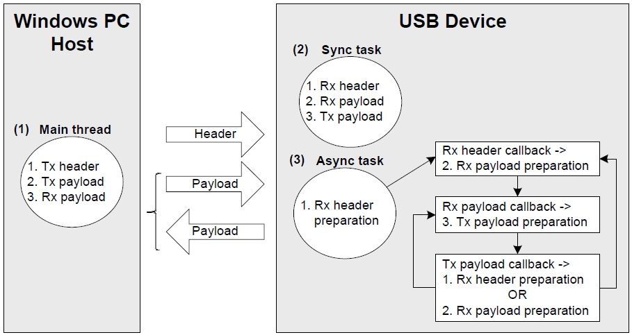
(1) The Windows application executes a simple protocol, which consists of sending a header indicating the total payload size, sending the data payload to the device, and receiving the same data payload back from the device. The data payload is split into small chunks of write and read operations of 512 bytes. The write operation is done using a bulk OUT endpoint, and the read uses a bulk IN endpoint.
(2) On the device, the Echo Sync application performs a series of tasks that execute in lockstep with the Windows PC, and the read and write operations performed on the device mirror those performed on the host. So, a read operation on the device implies a bulk OUT endpoint on the host, while a write on the device implies a bulk IN endpoint on the host. Both the device and host wait until the other has performed its task.
(3) The Echo Async application performs the same steps as the Sync task, but using the asynchronous API. The Async task starts the first asynchronous OUT transfer to receive the header. Then, a callback associated with the header reception is called by the device stack. It prepares the next asynchronous OUT transfer to receive the payload. The read payload callback sends the payload back to the host via an asynchronous IN transfer. The write payload callback is called and either prepares the next header reception if the entire payload has been sent to the host, or prepares a next OUT transfer to receive a new chunk of data payload. A side note: this task is also used in case of error during the protocol communication.
When the vendor device is first connected, Windows enumerates the device by retrieving the standard descriptors. Microsoft does not provide any specific driver for the Vendor class, so if you don't use the Microsoft OS descriptors, you must indicate to Windows which driver to load using an INF file (refer to About INF files for more details about INF). The INF file tells Windows to load the WinUSB generic driver (provided by Microsoft). Indicating the INF file to Windows needs to be done only once. Windows will then automatically recognize the vendor device and load the proper driver for any new connection. The process of indicating the INF file may vary according to the Windows operating system version:
Windows XP directly opens the “Found New Hardware Wizard”. Follow the different steps of the wizard until the page where you can indicate the path of the INF file.
Windows Vista and later won’t open a “Found New Hardware Wizard”. It will just indicate that no driver was found for the vendor device. You have to manually open the wizard. Open the Device Manager, the vendor device connected appears under the category ‘Other Devices’ with a yellow icon. Right-click on your device and choose ‘Update Driver Software...’ to open the wizard. Follow the different steps of the wizard until the page where you can indicate the path of the INF file.
Once the driver is successfully loaded, the Windows host application is ready to be launched. There are two executables:
EchoSync.exe for the Windows application with the synchronous communication API of USBDev_API
EchoAsync.exe for the Windows application with the asynchronous IN API of USBDev_API
The Windows application interacts with WinUSB driver via USBDev_API, which is a wrapper for the WinUSB driver. USBDev_API is provided by Micrium. Refer to USBDev_API for more details about USBDev_API and the WinUSB driver. The Echo Sync or Async demo will first determine the number of vendor devices connected to the PC. For each detected device, the demo will open a bulk IN and a bulk OUT pipe. Then the demo is ready to send/receive data to/from the device. You will have to enter the maximum number of transfers you want as shown in Figure - Demo Application at Startup in the USB Device Vendor Class Example Applications page.
Figure - Demo Application at Startup#
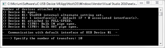
In the example Figure - Demo Application at Startup in the USB Device Vendor Class Example Applications page, the demo handles 10 transfers. Each transfer is sent after the header, following the simple protocol described in Figure - Echo Demo in the USB Device Vendor Class Example Applications page. The first transfer will have a data payload of 1 byte. Then, subsequent transfers will have their size incremented by 1 byte until the last transfer. In our example, the last transfer will have 10 bytes.
Figure - Demo Application Execution (Single Device) in the USB Device Vendor Class Example Applications page shows the execution.
Figure - Demo Application Execution (Single Device)#
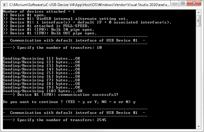
The demo will prompt you to perform another transfer. Figure - Demo Application Execution (Single Device) in the USB Device Vendor Class Example Applications page shows the example of a single device with one vendor interface. For composite devices, the demo is able to communicate with each vendor interface, and it will open bulk IN and OUT pipes for each one. You will be asked the maximum number of transfers for each interface in the device. Figure - Demo Application Execution (Composite Device) in the USB Device Vendor Class Example Applications page shows an example of a composite device.
Figure - Demo Application Execution (Composite Device)#
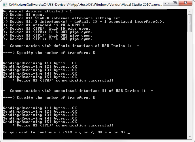
Figure - Demo Application Execution (Composite Device)
GUID#
A Globally Unique IDentifier (GUID) is a 128-bit value that uniquely identifies a class or other entity. Windows uses GUIDs for identifying two types of devices classes:
Device setup class
Device interface class
Windows assigns a device setup GUID to devices that are installed in all the same way, and which all use the same class installer and co-installers. Class installers and co-installers are DLLs that provide functions related to the installation of the device.
A device interface GUID provides the mechanism that applications use to communicate with the driver that has been assigned to all devices in a class. Refer to Using GUID for more details about the GUID.
The device setup class GUID is used in WinUSB_single.inf and WinUSB_composite.inf.These INF files define a new device setup class that will be added to the Windows registry under HKEY_LOCAL_MACHINE\System\CurrentControlSet\Control\Class when a vendor device is first connected. Listing - New Device Setup Class in the USB Device Vendor Class Example Applications page shows entries in the INF file that define the new device setup class.
Listing - New Device Setup Class#
Class = MyDeviceClass ; Name of the device setup class.
ClassGuid = {11111111-2222-3333-4444-555555555555} ; Device setup class GUIDThe INF file allows Windows to register all the information necessary to associate the driver Winusb.sys with the connected vendor device. The Windows Echo application is able to retrieve the attached vendor device thanks to the device interface class GUID. WinUSB_single.inf and WinUSB_composite.inf define the following device interface class GUID: {143f20bd-7bd2-4ca6-9465-8882f2156bd6}. The Echo application includes a header file called usbdev_guid.h. This header file defines the variable shown in Listing - GUID Global Variable in the USB Device Vendor Class Example Applications page.
Listing - GUID Global Variable#
GUID USBDev_GUID = {0x143f20bd,0x7bd2,0x4ca6,{0x94,0x65,0x88,0x82,0xf2,0x15,0x6b,0xd6}};USBDev_GUID is a structure whose fields represent the device interface class GUID that is defined in WinUSB_single.inf and WinUSB_composite.inf. The USBDev_GUID variable will be passed as a parameter to the function USBDev_Open(). A handle will be returned by USBDev_Open(), and the application uses this handle to access the device.
API#
This example uses only one API named Ex_USBD_Vendor_Init(). This function is normally called from a USB device core example.
USB Device Vendor Class Configuration#
To configure the Vendor class, there are two groups of configuration parameters:
USB Device Vendor Class Run-Time Application Specific Configurations#
Class Initialization#
To initialize the Micrium OS USB Device Vendor class, you call the function USBD_Vendor_Init(). This function takes one configuration argument which is described below.
p_qty_cfg#
p_qty_cfg is a pointer to a configuration structure of type USBD_VENDOR_QTY_CFG. Its purpose is to inform the USB device module about how many USB vendor objects to allocate.
Table - USBD_VENDOR_QTY_CFG configuration structure in the USB Device Vendor Class Run-Time Application Specific Configurations page describes each configuration field available in this configuration structure.
Table - USBD_VENDOR_QTY_CFG configuration structure#
Field | Description | Recommended Value |
|---|---|---|
.ClassInstanceQty | Number of class instances you will allocate via a call to the function USBD_Vendor_Add(). | 1 |
.ConfigQty | Number of configurations. Vendor class instances can be added to one or more configurations via a call to the function USBD_Vendor_ConfigAdd(). | 2 |
Optional Configurations#
This section describes the configurations that are optional. If you do not set them in your application, the default configurations will apply.
The default values can be retrieved via the structure USBD_Vendor_InitCfgDflt.
Note: These configurations must be set before you call the function USBD_Vendor_Init(). |
|---|
Table - Vendor Class Optional Configurations#
Configurations | Description | Type | Function to Call | Default | Field From Default Configuration Structure |
|---|---|---|---|---|---|
Microsoft extended properties quantity | Configures the number of Microsoft Extended properties that will be added per vendor class instance via a call to the function USBD_Vendor_MS_ExtPropertyAdd(). Note: This configuration is ignored when USBD_CFG_MS_OS_DESC_EN is set to DEF_DISABLED. | CPU_INT08U | USBD_Vendor_ConfigureMsExtPropertiesQty() | 1 | .MsExtPropertiesQty |
Memory segments | This module allocates some control data. It has the ability to use a specified memory segment. | MEM_SEG* | USBD_Vendor_ConfigureMemSeg() | .MemSegPtr |
USB Device Vendor Class Instance Configurations#
This section defines the configurations related to the Vendor class instances.
Class Instance Creation#
Creating a Vendor class instance is done by calling the function USBD_Vendor_Add(). This function takes three configuration arguments that are described below.
intr_en#
Boolean that indicates if a pair of interrupt endpoints should be added or not.
Value | Description |
|---|---|
DEF_ENABLED | A pair of IN/OUT endpoints will be added and made available to the embedded application. |
DEF_DISABLED | No interrupt endpoint will be added. Only a pair of Bulk IN/OUT endpoint will be available. |
interval#
If you set intr_en to DEF_ENABLED, you can specify the interrupt endpoints polling interval (in milliseconds).
If you set intr_en to DEF_DISABLED, you can set interval to 0 as it will be ignored by the class.
req_callback#
req_callback is a function that you can specify to handle the class specific control requests. If you don't use any class specific requests, you can set this to DEF_NULL.
Listing - Signature of Class Specific Request Function in the USB Device Vendor Class Instance Configurations page provides the expected signature of your class specific requests handler.
Listing - Signature of Class Specific Request Function#
CPU_BOOLEAN App_USBD_VendorReqHandle( CPU_INT08U class_nbr, (1)
CPU_INT08U dev_nbr, (2)
const USBD_SETUP_REQ *p_setup_req); (3)(1) Vendor class instance number.
(2) Device number.
(3) Pointer to received setup request from host.
USB Device Vendor Class Programming Guide#
This section explains how to use the Vendor class.
Initializing the USB Device Vendor Class#
To add a Vendor Class functionality to your device, you must first initialize the class by calling the function USBD_Vendor_Init().
Listing - Example of call to USBD_Vendor_Init() in the Initializing the USB Device Vendor Class page shows an example of a call to USBD_Vendor_Init() using default arguments. For more information about the configuration arguments that are passed to USBD_Vendor_Init(), see USB Device Vendor Class Run-Time Application Specific Configurations .
Listing - Example of call to USBD_Vendor_Init()#
RTOS_ERR err;
USBD_VENDOR_QTY_CFG vendor_qty_cfg;
vendor_qty_cfg.ClassInstanceQty = 1u;
vendor_qty_cfg.ConfigQty = 2u;
USBD_Vendor_Init(&vendor_qty_cfg,
&err);
if (err.Code != RTOS_ERR_NONE) {
/* An error occurred. Error handling should be added here. */
}Adding a USB Device Vendor Class Instance to your Device#
To add vendor class functionality to your device, you must first create an instance, then add it to your device's configuration(s). You can also optionally add one or more Microsoft Extended Properties to your class instance.
Adding the Vendor Class Instance to Your Device's Configuration(s)
Adding Microsoft Extended Properties to your Class Instance (Optional)
Creating a Vendor Class Instance#
Create a Vendor class instance by calling the function USBD_Vendor_Add().
Listing - Example of call to USBD_Vendor_Add() in the Adding a USB Device Vendor Class Instance to your Device page shows an example of a call to USBD_Vendor_Add() using default arguments. For more information about the configuration arguments to pass to USBD_Vendor_Add(), see USB Device Vendor Class Instance Configurations .
Listing - Example of call to USBD_Vendor_Add()#
CPU_INT08U class_nbr;
RTOS_ERR err;
class_nbr = USBD_Vendor_Add(DEF_DISABLED, (1)
0u, (2)
App_USBD_Vendor_VendorReq, (3)
&err);
if (err.Code != RTOS_ERR_NONE) {
/* An error occurred. Error handling should be added here. */
}(1) No Interrupt endpoints with this class instance.
(2) Interval is ignored since Interrupt endpoints are disabled.
(3) Callback function that is part of your application that handles vendor-specific class requests. See Communicating using the USB Device Vendor Class for more information.
Adding the Vendor Class Instance to Your Device's Configuration(s)#
Once you have created a vendor class instance, you can add it to a configuration by calling the function USBD_Vendor_ConfigAdd().
Listing - Example of call to USBD_Vendor_ConfigAdd() in the Adding a USB Device Vendor Class Instance to your Device page shows an example of a call to USBD_Vendor_ConfigAdd() using default arguments.
Listing - Example of call to USBD_Vendor_ConfigAdd()#
RTOS_ERR err;
USBD_Vendor_ConfigAdd(class_nbr, (1)
dev_nbr, (2)
config_nbr_fs, (3)
&err);
if (err.Code != RTOS_ERR_NONE) {
/* An error occurred. Error handling should be added here. */
}
USBD_Vendor_ConfigAdd(class_nbr, (4)
dev_nbr,
config_nbr_hs,
&err);
if (err.Code != RTOS_ERR_NONE) {
/* An error occurred. Error handling should be added here. */
}(1) Class number to add to the configuration returned by USBD_Vendor_Add().
(2) Device number returned by USBD_DevAdd().
(3) Configuration number (here adding it to a Full-Speed configuration).
(4) Adding the same class instance to the High-Speed configuration. This should be done only if you have a High-Speed device.
Adding Microsoft Extended Properties to your Class Instance (Optional)#
Once you have created a vendor class instance, you can add one or multiple Microsoft extended properties. Adding a Microsoft extended property is particularly useful so you can avoid having to provide an .inf file when connecting your device to a PC running Microsoft Windows OS.
You can add different types of extended properties, but the most common one is a property that will provide the GUID to Windows. For more information on GUID and on how Windows normally loads a driver for a USB device, see Host Operating Systems: Microsoft Windows . Adding a Microsoft Extended property is done by calling the function USBD_Vendor_MS_ExtPropertyAdd() .
To add a Microsoft extended property to your vendor class instance, you must set the configuration USBD_CFG_MS_OS_DESC_EN to DEF_ENABLED. For more information on this configuration, see USB Device Compile-Time Configuration . |
|---|
Listing - Adding a Microsoft GUID in the Adding a USB Device Vendor Class Instance to your Device page gives an example of how to add a property DeviceInterfaceGUID with a value of {143F20BD-7BD2-4CA6-9465-8882F2156BD6} to your Vendor class instance via the Microsoft Extended Properties.
Listing - Adding a Microsoft GUID#
static const CPU_INT08U App_USBD_Vendor_PropertyNameGUID[] = {
'D', 0u, 'e', 0u, 'v', 0u, 'i', 0u, 'c', 0u, 'e', 0u,
'I', 0u, 'n', 0u, 't', 0u, 'e', 0u, 'r', 0u, 'f', 0u, 'a', 0u, 'c', 0u, 'e', 0u,
'G', 0u, 'U', 0u, 'I', 0u, 'D', 0u, 0u, 0u
};
static const CPU_INT08U App_USBD_Vendor_MS_GUID[] = {
'{', 0u, '1', 0u, '4', 0u, '3', 0u, 'F', 0u, '2', 0u, '0', 0u, 'B', 0u, 'D', 0u,
'-', 0u, '7', 0u, 'B', 0u, 'D', 0u, '2', 0u, '-', 0u, '4', 0u, 'C', 0u, 'A', 0u, '6', 0u,
'-', 0u, '9', 0u, '4', 0u, '6', 0u, '5', 0u,
'-', 0u, '8', 0u, '8', 0u, '8', 0u, '2', 0u, 'F', 0u, '2', 0u, '1', 0u, '5', 0u, '6', 0u, 'B', 0u, 'D', 0u, '6', 0u, '}', 0u, 0u, 0u
};
RTOS_ERR err;
USBD_Vendor_MS_ExtPropertyAdd(class_nbr,
USBD_MS_OS_PROPERTY_TYPE_REG_SZ,
App_USBD_Vendor_PropertyNameGUID,
sizeof(App_USBD_Vendor_PropertyNameGUID),
App_USBD_Vendor_MS_GUID,
sizeof(App_USBD_Vendor_MS_GUID),
&err);
if (err.Code != RTOS_ERR_NONE) {
/* An error occurred. Error handling should be added here. */
}Communicating using the USB Device Vendor Class#
General#
The Vendor class offers the following functions to communicate with the host. For more details about the parameters of the function, see USB Device Vendor API .
Table - Vendor Communication API Summary#
Function name | Operation |
|---|---|
USBD_Vendor_Rd() | Receives data from host through bulk OUT endpoint. This function is blocking. |
USBD_Vendor_Wr() | Sends data to host through bulk IN endpoint. This function is blocking. |
USBD_Vendor_RdAsync() | Receives data from host through bulk OUT endpoint. This function is non-blocking. |
USBD_Vendor_WrAsync() | Sends data to host through bulk IN endpoint. This function is non-blocking. |
USBD_Vendor_IntrRd() | Receives data from host through interrupt OUT endpoint. This function is blocking. |
USBD_Vendor_IntrWr() | Sends data to host through interrupt IN endpoint. This function is blocking. |
USBD_Vendor_IntrRdAsync() | Receives data from host through interrupt OUT endpoint. This function is non-blocking. |
USBD_Vendor_IntrWrAsync() | Sends data to host through interrupt IN endpoint. This function is non-blocking. |
The vendor requests are also another way to communicate with the host. When managing vendor requests sent by the host, the application can receive or send data from or to the host using the control endpoint; you will need to provide an application callback passed as a parameter of USBD_Vendor_Add().
Synchronous Communication#
Synchronous communication means that the transfer is blocking. When a function is called, the application blocks until the transfer completes with or without an error. A timeout can be specified to avoid waiting forever.
Listing - Synchronous Bulk Read and Write Example in the Communicating using the USB Device Vendor Class page shows a read and write example that receives data from the host using the bulk OUT endpoint and sends data to the host using the bulk IN endpoint.
Listing - Synchronous Bulk Read and Write Example#
CPU_INT08U rx_buf[2];
CPU_INT08U tx_buf[2];
RTOS_ERR err;
(void)USBD_Vendor_Rd( class_nbr, (1)
(void *)&rx_buf[0], (2)
2u,
0u, (3)
&err);
if (err.Code != USBD_ERR_NONE) {
/* $$$$ Handle the error. */
}
(void)USBD_Vendor_Wr( class_nbr, (1)
(void *)&tx_buf[0], (4)
2u,
0u, (3)
DEF_FALSE, (5)
&err);
if (err.Code != USBD_ERR_NONE) {
/* $$$$ Handle the error. */
}(1) The class instance number created with USBD_Vendor_Add() provides an internal reference to the Vendor class to route the transfer to the proper bulk OUT or IN endpoint.
(2) The application must ensure that the buffer provided to the function is large enough to accommodate all the data. Otherwise, synchronization issues might happen.
(3) In order to avoid an infinite blocking situation, a timeout expressed in milliseconds can be specified. A value of ‘0’ makes the application task wait forever.
(4) The application provides the initialized transmit buffer.
(5) If this flag is set to DEF_TRUE, and the transfer length is multiple of the endpoint maximum packet size, the device stack will send a zero-length packet to the host to signal the end of the transfer.
The use of interrupt endpoint communication functions, USBD_Vendor_IntrRd() and USBD_Vendor_IntrWr(), is similar to bulk endpoint communication functions presented in Listing - Synchronous Bulk Read and Write Example in the Communicating using the USB Device Vendor Class page.
Asynchronous Communication#
Asynchronous communication means that the transfer is non-blocking. When a function is called, the application passes the transfer information to the device stack and does not block. Other application processing can be done while the transfer is in progress over the USB bus. Once the transfer has completed, a callback function is called by the device stack to inform the application about the transfer completion. Listing - Asynchronous Bulk Read and Write Example in the Communicating using the USB Device Vendor Class page shows an example of asynchronous read and write.
Listing - Asynchronous Bulk Read and Write Example#
void App_USBD_Vendor_Comm (CPU_INT08U class_nbr)
{
CPU_INT08U rx_buf[2];
CPU_INT08U tx_buf[2];
RTOS_ERR err;
USBD_Vendor_RdAsync( class_nbr, (1)
(void *)&rx_buf[0], (2)
2u,
App_USBD_Vendor_RxCmpl, (3)
DEF_NULL, (4)
&err);
if (err.Code != USBD_ERR_NONE) {
/* $$$$ Handle the error. */
}
USBD_Vendor_WrAsync( class_nbr, (1)
(void *)&tx_buf[0], (5)
2u,
App_USBD_Vendor_TxCmpl, (3)
DEF_NULL, (4)
DEF_FALSE, (6)
&err);
if (err.Code != USBD_ERR_NONE) {
/* $$$$ Handle the error. */
}
}
static void App_USBD_Vendor_RxCmpl (CPU_INT08U class_nbr, (3)
void *p_buf,
CPU_INT32U buf_len,
CPU_INT32U xfer_len,
void *p_callback_arg,
USBD_ERR err)
{
if (err.Code == USBD_ERR_NONE) {
/* $$$$ Do some processing. */
} else {
/* $$$$ Handle the error. */
}
}
static void App_USBD_Vendor_TxCmpl (CPU_INT08U class_nbr, (3)
void *p_buf,
CPU_INT32U buf_len,
CPU_INT32U xfer_len,
void *p_callback_arg,
USBD_ERR err)
{
if (err.Code == USBD_ERR_NONE) {
/* $$$$ Do some processing. */
} else {
/* $$$$ Handle the error. */
}
}(1) The class instance number provides an internal reference to the Vendor class to route the transfer to the proper bulk OUT or IN endpoint.
(2) The application must ensure that the buffer provided is large enough to accommodate all the data. Otherwise, there may be synchronization issues.
(3) The application provides a callback function pointer passed as a parameter. Upon completion of the transfer, the device stack calls this callback function so that the application can finalize the transfer by analyzing the transfer result. For instance, on completion of a read operation, the application might perform processing on the received data. Upon write completion, the application can indicate if the write was successful and how many bytes were sent.
(4) An argument associated with the callback can be also passed. Then in the callback context, some private information can be retrieved.
(5) The application provides the initialized transmit buffer.
(6) If this flag is set to DEF_TRUE, and the transfer length is a multiple of the endpoint maximum packet size, the device stack will send a zero-length packet to the host to signal the end of transfer.
The use of interrupt endpoint communication functions, USBD_Vendor_IntrRdAsync() and USBD_Vendor_IntrWrAsync(), is similar to the bulk endpoint communication functions presented in Listing - Asynchronous Bulk Read and Write Example in the Communicating using the USB Device Vendor Class page.
Vendor Request#
The USB 2.0 specification defines three types of requests: standard, class, and vendor. All standard requests are handled directly by the core layer, while class requests are managed by the proper associated class.
Vendor requests can be processed by the vendor class. To process vendor requests, you must provide an application callback as a parameter of USBD_Vendor_Add() . Once a vendor request is received by the USB device, it must be decoded properly. Listing - Example of Vendor Request Decoding in the Communicating using the USB Device Vendor Class page shows an example of vendor request decoding.
Certain requests may be required to receive from or send to the host during the data stage of a control transfer. If no data stage is present, you only have to decode the Setup packet. This example shows the three types of data stage management: no data, data OUT and data IN.
Listing - Example of Vendor Request Decoding#
#define APP_VENDOR_REQ_NO_DATA 0x01u
#define APP_VENDOR_REQ_RECEIVE_DATA_FROM_HOST 0x02u
#define APP_VENDOR_REQ_SEND_DATA_TO_HOST 0x03u
#define APP_VENDOR_REQ_DATA_BUF_SIZE 50u
static CPU_INT08U AppVendorReqBuf[APP_VENDOR_REQ_DATA_BUF_SIZE];
static CPU_BOOLEAN App_USBD_Vendor_VendorReq ( CPU_INT08U class_nbr,
CPU_INT08U dev_nbr,
const USBD_SETUP_REQ *p_setup_req) (1)
{
CPU_BOOLEAN valid;
RTOS_ERR err_usb;
CPU_INT16U req_len;
(void)&class_nbr;
switch(p_setup_req->bRequest) { (2)
case APP_VENDOR_REQ_NO_DATA: (3)
APP_TRACE_DBG(("Vendor request [0x%X]:\r\n", p_setup_req->bRequest));
APP_TRACE_DBG(("wIndex = %d\r\n", p_setup_req->wIndex));
APP_TRACE_DBG(("wLength = %d\r\n", p_setup_req->wLength));
APP_TRACE_DBG(("wValue = %d\r\n", p_setup_req->wValue));
valid = DEF_OK;
break;
case APP_VENDOR_REQ_RECEIVE_DATA_FROM_HOST: (4)
req_len = p_setup_req->wLength;
if (req_len > APP_VENDOR_REQ_DATA_BUF_SIZE) {
return (DEF_FAIL); /* Not enough room to receive data. */
}
APP_TRACE_DBG(("Vendor request [0x%X]:\r\n", p_setup_req->bRequest));
/* Receive data via Control OUT EP. */
(void)USBD_CtrlRx( dev_nbr,
(void *)&AppVendorReqBuf[0u],
req_len,
0u, /* Wait transfer completion forever. */
&err_usb);
if (err_usb.Code != USBD_ERR_NONE) {
APP_TRACE_DBG(("Error receiving data from host: %d\r\n", err_usb));
valid = DEF_FAIL;
} else {
APP_TRACE_DBG(("wIndex = %d\r\n", p_setup_req->wIndex));
APP_TRACE_DBG(("wLength = %d\r\n", p_setup_req->wLength));
APP_TRACE_DBG(("wValue = %d\r\n", p_setup_req->wValue));
APP_TRACE_DBG(("Received %d octets from host via Control EP OUT\r\n", req_len));
valid = DEF_OK;
}
break;
case APP_VENDOR_REQ_SEND_DATA_TO_HOST: (5)
APP_TRACE_DBG(("Vendor request [0x%X]:\r\n", p_setup_req->bRequest));
req_len = APP_VENDOR_REQ_DATA_BUF_SIZE;
Mem_Set((void *)&AppVendorReqBuf[0u], /* Fill buf with a pattern. */
'A',
req_len);
/* Send data via Control IN EP. */
(void)USBD_CtrlTx( dev_nbr,
(void *)&AppVendorReqBuf[0u],
req_len,
0u, /* Wait transfer completion forever. */
DEF_NO,
&err_usb);
if (err_usb.Code != USBD_ERR_NONE) {
APP_TRACE_DBG(("Error sending data to host: %d\r\n", err_usb));
valid = DEF_FAIL;
} else {
APP_TRACE_DBG(("wIndex = %d\r\n", p_setup_req->wIndex));
APP_TRACE_DBG(("wLength = %d\r\n", p_setup_req->wLength));
APP_TRACE_DBG(("wValue = %d\r\n", p_setup_req->wValue));
APP_TRACE_DBG(("Sent %d octets to host via Control EP IN\r\n", req_len));
valid = DEF_OK;
}
break;
default: (6)
valid = DEF_FAIL; /* Request is not supported. */
break;
}
return (valid);
}(1) The core will pass the Setup packet content to your application. The structure USBD_SETUP_REQ contains the same fields as defined by the USB 2.0 specification (refer to section "9.3 USB Device Requests" of the specification for more details):
typedef struct usbd_setup_req {
CPU_INT08U bmRequestType; /* Characteristics of request. */
CPU_INT08U bRequest; /* Specific request. */
CPU_INT16U wValue; /* Varies according to request. */
CPU_INT16U wIndex; /* Varies according to request; typically used as index.*/
CPU_INT16U wLength; /* Transfer length if data stage present. */
} USBD_SETUP_REQ;(2) Determine the request. You may use a switch statement if you are using different requests. In this example, there are three different requests corresponding to the three types of the data stage: APP_VENDOR_REQ_NO_DATA, APP_VENDOR_REQ_RECEIVE_DATA_FROM_HOST, and APP_VENDOR_REQ_SEND_DATA_TO_HOST.
(3) If no data stage is present, you only need to decode the other fields. The presence of a data stage or not is indicated by the field wLength being non-null or null.
(4) If the host sends data to the device, you must call the function USBD_CtrlRx() . The buffer provided should be able to contain up to wLength bytes. If any error occurs, return DEF_FAIL to the core that will stall the status stage of the control transfer, indicating to the host that the request cannot be processed. DEF_OK is returned in case of success.
(5) If the host receives data from the device, you must call the function USBD_CtrlTx(). If any error occurs, return DEF_FAIL to the core that will stall the status stage of the control transfer, indicating to the host that the request cannot be processed. DEF_OK is returned in case of success.
(6) In this example, all requests not recognized are marked by returning DEF_FAIL to the core. This one will stall the data or status stage of the control transfer indicating to the host that the request is not supported.
The host sends vendor requests using the function USBDev_CtrlReq(). Refer to the page USBDev_API for more details about how to send vendor requests on the host side.
USBDev_API#
The Windows host application communicates with a vendor device through USBDev_API. The latter is a wrapper developed by Micrium allowing the application to access the WinUSB functionalities to manage a USB device. Windows USB (WinUSB) is a generic driver for USB devices. The WinUSB architecture consists of a kernel-mode driver (winusb.sys) and a user-mode dynamic link library (winusb.dll) that exposes WinUSB functions. USBDev_API eases the use of WinUSB by providing a comprehensive API (refer to the USBDev_API Functions Reference for the complete list). Figure - USBDev_API and WinUSB in the USBDev_API page shows the USBDev_API library and WinUSB.
Figure - USBDev_API and WinUSB#
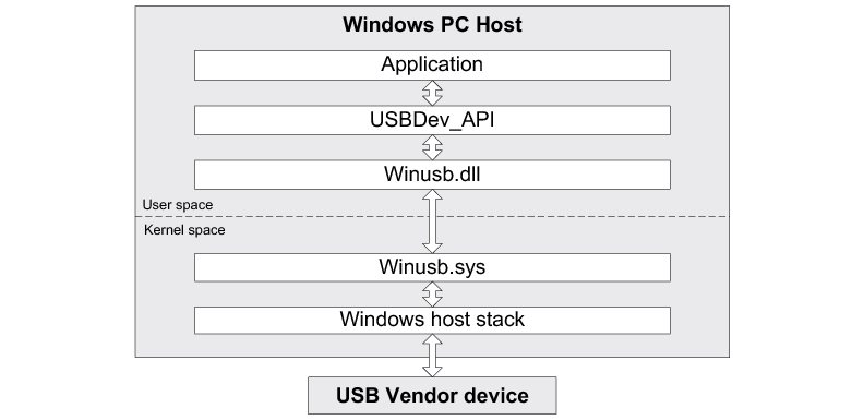
For more about WinUSB architecture, refer to Microsoft’s MSDN online documentation at: http://msdn.microsoft.com/en-us/library/ff540207(v=VS.85).aspx
Management#
USBDev_API offers the following functions to manage a device and its function’s pipes.
Function name | Operation |
|---|---|
USBDev_DevQtyGet | Gets number of devices belonging to a specified Globally Unique IDentifier (GUID) and connected to the host. |
USBDev_Open() | Opens a device. |
USBDev_Close | Closes a device. |
USBDev_BulkIn_Open | Opens a bulk IN pipe. |
USBDev_BulkOut_Open | Opens a bulk OUT pipe. |
USBDev_IntrIn_Open | Opens an interrupt IN pipe. |
USBDev_IntrOut_Open | Opens an interrupt OUT pipe. |
USBDev_PipeClose | Closes a pipe. |
Table - USBDev_API Device and Pipe Management API
Listing - USBDev_API Device and Pipe Management Example in the USBDev_API page shows an example of device and pipe management. The steps to manage a device typically consist in:
Opening the vendor device connected to the host.
Opening required pipes for this device.
Communicating with the device via the open pipes.
Closing pipes.
Closing the device.
Listing - USBDev_API Device and Pipe Management Example#
HANDLE dev_handle;
HANDLE bulk_in_handle;
HANDLE bulk_out_handle;
DWORD err;
DWORD nbr_dev;
nbr_dev = USBDev_DevQtyGet(USBDev_GUID, &err); (1)
if (err != ERROR_SUCCESS) {
/* $$$$ Handle the error. */
}
dev_handle = USBDev_Open(USBDev_GUID, 1, &err); (2)
if (dev_handle == INVALID_HANDLE_VALUE) {
/* $$$$ Handle the error. */
}
bulk_in_handle = USBDev_BulkIn_Open(dev_handle, 0, 0, &err); (3)
if (bulk_in_handle == INVALID_HANDLE_VALUE) {
/* $$$$ Handle the error. */
}
bulk_out_handle = USBDev_BulkOut_Open(dev_handle, 0, 0, &err); (3)
if (bulk_out_handle == INVALID_HANDLE_VALUE) {
/* $$$$ Handle the error. */
}
/* Communicate with the device. */ (4)
USBDev_PipeClose(bulk_in_handle, &err); (5)
if (err != ERROR_SUCCESS) {
/* $$$$ Handle the error. */
}
USBDev_PipeClose(bulk_out_handle, &err);
if (err != ERROR_SUCCESS) {
/* $$$$ Handle the error. */
}
USBDev_Close(dev_handle, &err); (6)
if (err != ERROR_SUCCESS) {
/* $$$$ Handle the error. */
}(1) Get the number of devices connected to the host under the specified GUID. A GUID provides a mechanism for applications to communicate with a driver assigned to devices in a class. The number of devices could be used in a loop to open at once all the devices. In this example, one device is assumed.
(2) Open the device by retrieving a general device handle. This handle will be used for pipe management and communication.
(3) Open a bulk pipe by retrieving a pipe handle. In the example, a bulk IN and a bulk OUT pipes are open. If the pipe does not exist for this device, an error is returned. When opening a pipe, the interface number and alternate setting number are specified. In the example, bulk IN and OUT pipes are part of the default interface. Opening an interrupt IN and OUT pipes with USBDev_IntIn_Open() or USBDev_IntOut_Open() is similar to bulk IN and OUT pipes.
(4) Transferring data on the open pipes can take place now. The pipe communication is described in the Communication section.
(5) Close a pipe by passing the associated handle. The closing operation aborts any transfer in progress for the pipe and frees any allocated resources.
(6) Close the device by passing the associated handle. The operation frees any allocated resources for this device. If a pipe has not been closed by the application, this function will close any forgotten open pipes.
Communication#
Synchronous#
Synchronous communication means that the transfer is blocking. Upon function call, the application blocks until the end of transfer is completed with or without an error. A timeout can be specified to avoid waiting forever. Listing - USBDev_API Synchronous Read and Write Example in the USBDev_API page presents a read and write example using a bulk IN pipe and a bulk OUT pipe.
Listing - USBDev_API Synchronous Read and Write Example#
UCHAR rx_buf[2];
UCHAR tx_buf[2];
DWORD err;
(void)USBDev_PipeRd(bulk_in_handle, (1)
&rx_buf[0], (2)
2u,
5000u, (3)
&err);
if (err != ERROR_SUCCESS) {
/* $$$$ Handle the error. */
}
(void)USBDev_PipeWr(bulk_out_handle, (1)
&tx_buf[0], (4)
2u,
5000u, (3)
&err);
if (err != ERROR_SUCCESS) {
/* $$$$ Handle the error. */
}(1) The pipe handle gotten with USBDev_BulkIn_Open() or USBDev_BulkOut_Open() is passed to the function to schedule the transfer for the desired pipe.
(2) The application provides a receive buffer to store the data sent by the device.
(3) To avoid an infinite blocking situation, a timeout expressed in milliseconds can be specified. A value of ‘0’ makes the application thread wait forever. In the example, a timeout of 5 seconds is set.
(4) The application provides the transmit buffer that contains the data for the device.
Asynchronous#
Asynchronous communication means that the transfer is non-blocking. Upon function call, the application passes the transfer information to the device stack and does not block. Other application processing can be done while the transfer is in progress over the USB bus. Once the transfer has completed, a callback is called by USBDev_API to inform the application about the transfer completion.
Listing - USBDev_API Asynchronous Read Example in the USBDev_API page presents a read example. The asynchronous write is not offered by USBDev_API.
Listing - USBDev_API Asynchronous Read Example#
UCHAR rx_buf[2];
DWORD err;
USBDev_PipeRdAsync( bulk_in_handle, (1)
&rx_buf[0], (2)
2u,
App_PipeRdAsyncComplete, (3)
(void *)0u, (4)
&err);
if (err != ERROR_SUCCESS) {
/* $$$$ Handle the error. */
}
static void App_PipeRdAsyncComplete(void *p_buf, (3)
DWORD buf_len,
DWORD xfer_len,
void *p_callback_arg,
DWORD err)
{
(void)p_buf;
(void)buf_len;
(void)xfer_len;
(void)p_callback_arg; (4)
if (err == ERROR_SUCCESS) {
/* $$$$ Process the received data. */
} else {
/* $$$$ Handle the error. */
}
}(1) The pipe handle gotten with USBDev_BulkIn_Open() is passed to the function to schedule the transfer for the desired pipe.
(2) The application provides a receive buffer to store the data sent by the device.
(3) The application provides a callback passed as a parameter. Upon completion of the transfer, USBDev_API calls this callback so that the application can finalize the transfer by analyzing the transfer result. For instance, upon read operation completion, the application may do a certain processing with the received data.
(4) An argument associated to the callback can also be passed. Then, in the callback context, some private information can be retrieved.
Control Transfer#
You can communicate with the device through the default control endpoint by using the function USBDev_CtrlReq(). You will be able to define the three types of requests (standard, class or vendor) and to use the data stage or not of a control transfer to move data. More details about control transfers can be found in “Universal Serial Bus Specification, Revision 2.0, April 27, 2000”, section 5.5 and 9.3.