System Level Test Setup#
Introduction#
For us to be able to confirm that our coexistence solutions truly add value to our customers' products, we felt the need to have a test setup which could measure system level performance in a given coexistence scenario. We hope that seeing these features in action provides a lot of value to the reader through demonstrating their effectiveness in countering the negative effects of coexistence.
When quantifying coexistence performance, it is important to choose the measured parameters correctly. We will talk about this in a bit more detail later but generally, measuring high level (application layer) performance is the best choice since there are a lot of factors influencing performance directly tied to application configuration (such as timings, or how "generous" is the Wi-Fi device in terms of giving up air time).
Physical Test Setup#
In this section, we will explain how we measured the system level performance of our coexistence solutions, and why we made the choices that we did for this particular test setup. The main goal was to demonstrate how our coexistence solutions can help our customers in achieving good application layer performance for a device that implements both high throughput Wi-Fi and a low power IoT protocol (in this case, Zigbee).
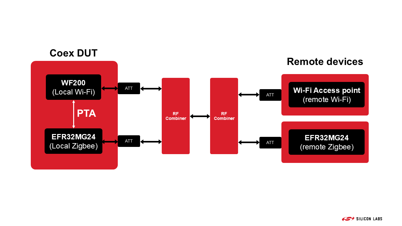
For this, we created a conducted test setup which can be seen below in a simple block diagram. Our DUT (Device Under Test) used 2 radios: a WF200 for Wi-Fi and an EFR32MG24 for Zigbee. These were connected together using a 3-line PTA interface, plus an additional signal that carried the "PA Enabled" signal of the WF200. This latter is needed for the Signal Identifier feature of the MG24, which we will discuss briefly later. The PTA connections were made between the development kits using our Silicon Labs Coexistence Development Kit.
Additionally, all relevant signals of the DUT were monitored using a logic analyzer. This is useful for both debugging and demonstrating correct operation. The Coexistence Development Kit is also useful for this purpose.
The polarities of all PTA signals can be configured through Simplicity Studio. In this case, they were:
REQUEST: active HIGH
GRANT: active LOW
PRIORITY: active LOW
All other monitored signals were set to active HIGH.
All DUTs have been placed inside shielded boxes, and only well isolated RF cables were used for connecting them (these shielded RF boxes are represented by the red rectangles in the picture above).
All the tests described in this application note have been performed using overlapping channels (2412 MHz for Wifi and 2405 MHz for Zigbee).
It is very important to note that the results of these tests depend hugely on the exact setup that is being tested. We believe that the setup we used is good for demonstrating coexistence fundamentals, but the exact numeric results of tests like these can vary wildly from setup to setup.
Testing Process and Measured Parameters#
The question quickly arises: what are the parameters of a system like this that we should be testing? There are quite a few options, from which different ones are relevant for different situations. In the end, Silicon Labs settled on measuring Wi-Fi throughput, Zigbee application level packet loss rate, and the number of Zigbee MAC layer retries.
For a home Wi-Fi system, the metric most commonly used for characterizing a connection is the maximum available throughput, so that is the logical choice. For a more IoT focused Wi-Fi device, this might not be true. For Zigbee, for a low duty cycle network (which is usually the case for a Zigbee application), application layer packet loss rate and the number of retries that occurs for a given number of packets would be the most important number from an end user point of view, since these have the most direct impact on actual application performance. An application layer packet loss means that the packet will never reach its destination, and thus the basic function of the Zigbee communication link is not working; for example, a light doesn't switch on when the user presses the switch. A high number of MAC layer retries has a high impact on the current consumption, and thus battery life, of a battery powered end node trying to send a message, since it has to send it out multiple times instead of just once.
For Wi-Fi throughput testing, Silicon Labs used the industry standard iperf3 software. The laboratory PC, which was connected to the Wi-Fi Access Point through LAN, was running an iperf server, and the WF200 was running a throughput test through the Wi-Fi connection. For Zigbee testing, the Z3Light (for the local Zigbee device) and Z3Switch (for the remote Zigbee device) examples were used, together with the Throughput plugin, which makes it possible to run throughput tests and get the desired metrics afterwards through a simple serial connection.
In these tests, the remote Zigbee device was trying to send packets to the local device every 5 seconds, and the results of this test was recorded. This setup (local Zigbee as the receiver, remote Zigbee as the transmitter) was chosen because RX performance is usually the most problematic. In a Zigbee TX scenario, a simple PTA connections is sufficient since the device can wait for the GRANT signal, then transmit when it is asserted. RX is more complicated, since the Zigbee device has to first detect that there is a transmission, which in itself is impacted by a local active Wi-Fi signal.
Tested Use Cases#
During our testing, 3 different cases have been measured. These were selected to provide a good demonstration on how useful different managed coexistence options can be for a device using multiple radios.
For a detailed description of the options discussed below, please see Zigbee and OpenThread Coexistence with Wi-Fi and Bluetooth Coexistence with Wi-Fi.
Case 1: Unmanaged Coexistence#
In this case, PTA was disabled on both the local Wi-Fi and Zigbee devices. This use case represents devices that are impacted by coexistence but do not implement any management features for it.
Case 2: Managed Coexistence with PWM Enabled#
In this case, a 3-wire PTA configuration was used (GRANT, REQUEST, PRIORITY). The PRIORITY line was set to assert every time the REQUEST line was asserted. This setting is configurable to represent a true priority difference between events in a real application, but since this example situation did not have any high/low priority distinctions, it was not needed.
For this case, the PWM feature was also enabled. This basically means that the Zigbee device asserts REQUEST periodically with a given duty cycle (20% for this testing). This might be needed for more stable RX performance when the Wi-Fi radio is transmitting with a high duty cycle. In such a scenario, there is only a very low chance that the Zigbee radio will be able to detect a Zigbee packet coming in and assert the REQUEST line for RX reception. Periodically giving some air time to the Zigbee radio for listening for packets means that the chance of detecting one (or one of its retries) will be much higher.
The cost of the PWM feature is that the co-located Wi-Fi radio will not be able to transmit in a significant portion of the available air time, even when there is no actual Zigbee activity present.
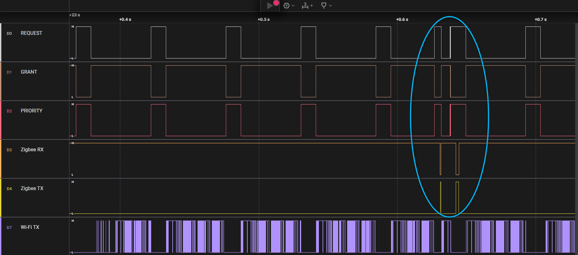
The picture below shows a capture of how the PTA lines behave in this configuration. As can be seen, the REQUEST and PRIORITY lines are regularly asserted (and GRANT as well, when the Wi-Fi DUT grants access to the Zigbee device). It is quite obvious from the Wi-Fi TX line that Wi-Fi maximum throughput would be hindered in such a situation because of the regular gaps in it.
While the PWM feature is active, the PTA lines still function the same way as before. For example, here the Zigbee device was able to detect an incoming frame outside of the PWM window, highlighted in the picture below, so it asserted REQUEST and PRIORITY until it completed the reception and sent back and ACK message. After that, it also used the regular PWM window for a transmission.
Case 3: Managed Coexistence with Signal Identifier Enabled#
For this use case, the basic PTA settings were the same as in Case 2. The biggest difference is that instead of the PWM feature, the Signal Identifier was used.
For this option to be available, another line has to be connected between the two radios, in addition to the 3 wires of the PTA interface. This line needs to be the "PA enabled" signal of the Wi-Fi radio that the Zigbee device can detect.
The Signal Identifier feature lets a low power IoT chip detect a certain type of signal in an extremely short amount of time. The minimum time needed is so low that the Wi-Fi protocol's mandatory IFS (interframe space) is enough for detection to occur. This means, that the Zigbee DUT can detect a valid Zigbee signal even if the Wi-Fi radio is transmitting at a maximum duty cycle.
When using the Signal Identifier feature instead of PWM, Zigbee RX performance and Wi-Fi throughput can both be protected, since this way, the Wi-Fi radio only needs to stop transmitting when a Zigbee packet actually arrives, instead of periodically stopping because of the PWM on the REQUEST line.
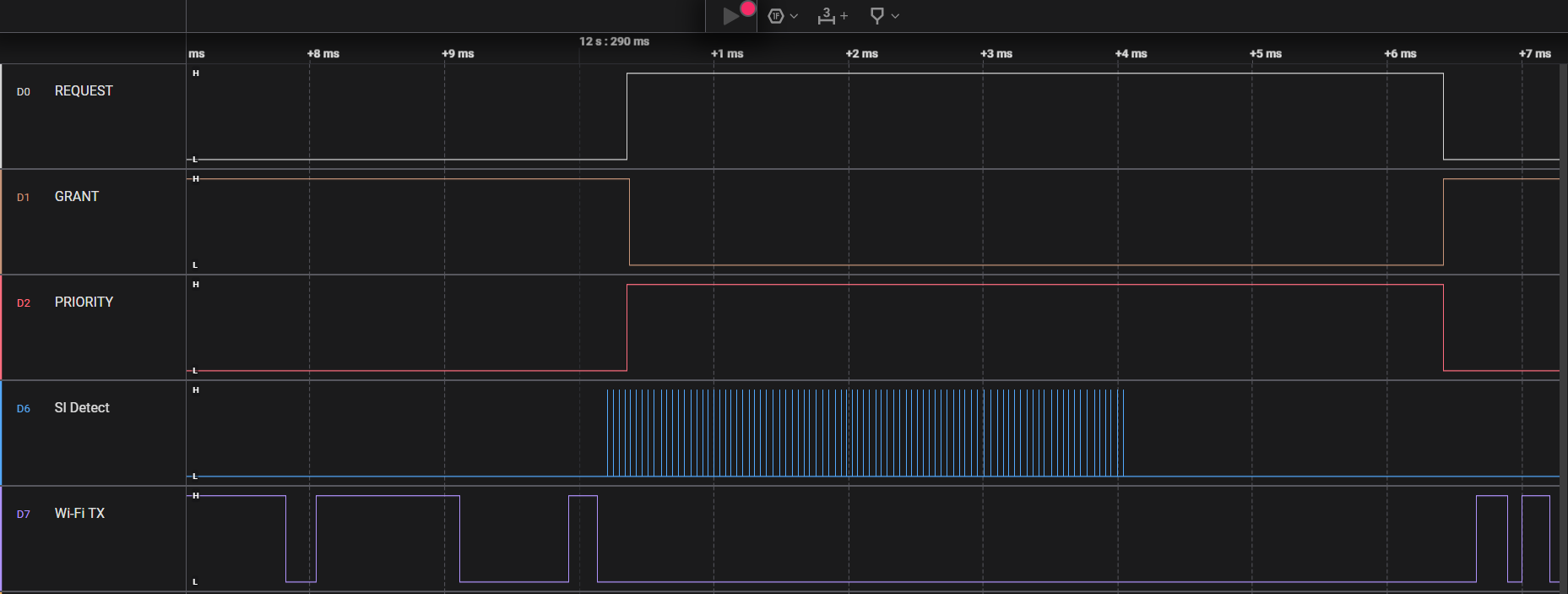
A small demonstration on how the Signal Identifier functions can be seen in the picture below. When the Zigbee radio is notified that the Wi-Fi device is not transmitting, through the de-assertion of the Wi-Fi TX line, the Signal Identifier starts working. If it detects an active Zigbee transmission, it asserts an internal signal, which can be seen on the SI Detect line below. Then, the Zigbee device can assert REQUEST and, if GRANT is then asserted by the Wi-Fi device, receive the expected retry packet.