Configuring Antenna Diversity#
The antenna diversity configuration options available for OpenThread consist of selecting Rx and/or Tx antenna diversity and configuring the underlying peripherals correctly. To configure antenna diversity, you must be familiar with your device’s overall antenna configuration, that is, if it uses a FEM/LNA for either Tx or Rx, and also be familiar with the device’s pin layout. Check the data sheet for your device for these settings or contact Silicon Labs Support if you have questions.
These instructions assume you have installed Simplicity Studio 5 and the OpenThread SDK (Software Development Kit), and that you have a project open in the Simplicity IDE (integrated development environment).
The steps to set up antenna diversity are described in detail below. In summary:
Install the Antenna Diversity component.
Configure the RAIL Utility - Antenna Diversity Configuration component.
Configure Antenna Pin configurations.
Configure the FEM (Optional).
Install Antenna Diversity Component#
On the SOFTWARE COMPONENTS tab, search for antenna in the ‘component’s name’ search field (at the top right).
Under OpenThread components, select the Antenna Diversity component and click Install as shown in the following figure.
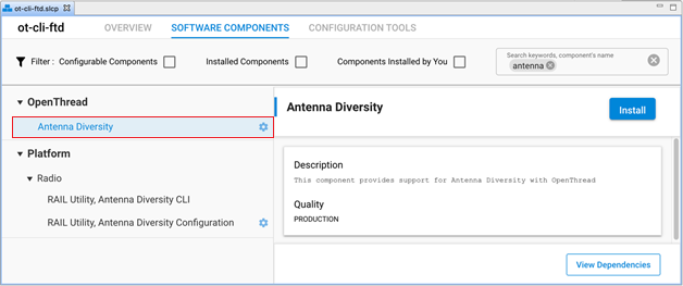
Installing the Antenna Diversity component will install the RAIL Utility, Antenna Diversity Configuration component for your project.
Note: For Silicon Labs OpenThread SDK releases prior to 1.2.0.0, select and install the RAIL Utility, Antenna Diversity Configuration component directly under Platform components.
Configure RAIL Utility - Antenna Diversity Configuration Component#
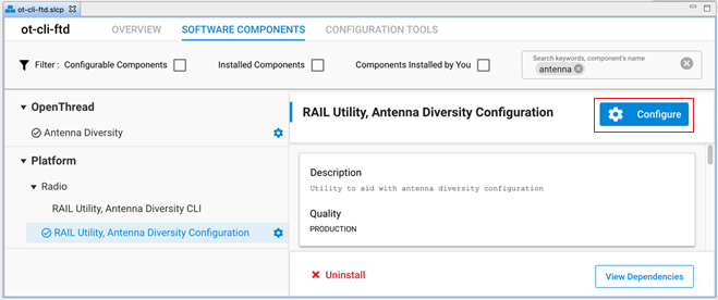
Once the Antenna Diversity Configuration component is successfully installed, click Configure or the configure symbol next to the RAIL Utility - Antenna Diversity Configuration component name as shown in the following figure.
Configure Tx Diversity#
The default configuration in the Antenna Diversity Configuration component for Tx Diversity is disabled. To enable Tx Diversity, select the Enable Antenna Diversity option from the Tx Antenna Diversity Mode drop-down menu as shown in the following figure.
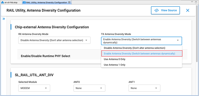
The different options for TX Antenna Diversity Mode are as follows:
Disable Antenna Diversity: Antenna Diversity component does not control ANTENNA_SELECT_GPIO.
Enable Antenna Diversity: Tx antenna selection is dynamic and Tx diversity is enabled.
Use Antenna 0 only: ANTENNA_SELECT_GPIO is set to high during Tx.
Use Antenna 1 only: ANTENNA_SELECT_GPIO is set to low during Tx.
Configure Rx Diversity#
The default configuration in the Antenna Diversity Configuration component for Rx Diversity is disabled. To enable Rx Diversity, select the Enable Antenna Diversity option from the Rx Antenna Diversity Mode drop-down menu as shown in the following figure.
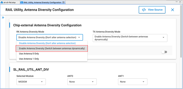
Similar to TX Antenna Diversity Mode, the different options for RX Antenna Diversity Mode are as follows:
Disable Antenna Diversity: Antenna Diversity component does not control ANTENNA_SELECT_GPIO.
Enable Antenna Diversity: Rx antenna selection is dynamic and Rx diversity is enabled.
Use Antenna 0 only: ANTENNA_SELECT_GPIO is set to high during Rx.
Use Antenna 1 only: ANTENNA_SELECT_GPIO is set to low during Rx.
Configure Rx and Tx Diversity#
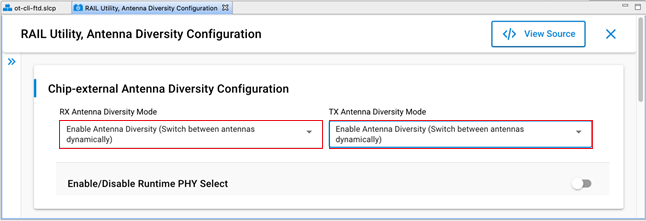
To configure both Rx and Tx antenna diversity, select the Enable Antenna Diversity option for both the Rx and Tx Antenna Diversity Mode as shown in the following figure.
Configure Antenna Pins#
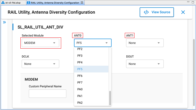
To configure Antenna pins, use the SL_RAIL_UTIL_ANT_DIV section of the component configurations.
The available antenna pins are:
Antenna select (ANT0): Pin used to control the external antenna switch.
Complementary antenna select (ANT1): Pin for the inverted external antenna signal.
For Rx Antenna Diversity (either alone or with Tx diversity), you must select the antenna port pin through the Modem peripheral.
From the Selected Module drop-down menu, select the MODEM option.
Select the pins for Antenna Select (ANT0) and, if applicable, Complementary antenna select (ANT1). The Antenna select signal goes high to select Antenna 0 and low to select Antenna 1.
For Tx Antenna Diversity (being configured alone), you can set the Antenna select (ANT0) and the Complementary antenna select (ANT1) pins either directly or Tx Antenna Diversity can inherit the setting from Modem Peripheral.
Note: Do not modify DCLK, DIN, and DOUT.
Configure the FEM (optional)#
If antenna diversity is implemented using an FEM, you must:
Install the Radio Utility, FEM component.
Configure the component.
Install Radio Utility, FEM Component#
This procedure is similar to the one for Antenna Diversity.
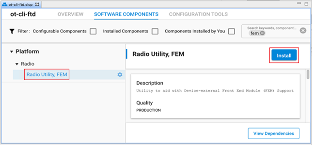
On the SOFTWARE COMPONENTS tab, search for fem in the ‘component’s name’ search field (at the top right).
Under Platform components, select the Radio Utility, FEM component and click Install as shown in the following figure.
Configure the FEM Component#
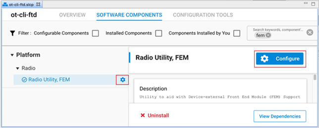
Once the FEM component is successfully installed, click Configure or the configure symbol next to the component name and configure the options as per the FEM datasheet.
Not all FEM configuration options apply to all FEMs. Specifically Bypass and Tx Power only apply to FEMs with the pins to support the features. Check your FEM datasheet for the settings required.
Note: Because there are a limited number of PRS channels, you must take care so they do not conflict with channels that might be selected in other plugins.
The main FEM configuration options are:
Enable RX mode: Configures RX mode on the FEM. This option is disabled by default and must be enabled along with the Antenna Diversity Component for the underlying antenna diversity radio configuration settings to be used. If it is disabled, then the standard radio configuration settings are used.
Enable TX mode: Configures TX mode on the FEM. This option is disabled by default.
Enable Bypass Mode (Optional): Enables communication that bypasses the LNA (Low Noise Amplifier).
Enable TX High Power Mode (Optional): Enables high power Tx, Enable low power Tx if disabled.
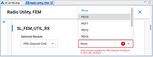
RX PRS channel (SL_FEM_UTIL_RX): PRS Channel for Rx control (FEM pin CRX). If no Tx is defined, it is a dual-use (Rx/Tx) pin. The options are Disabled or a channel number. Select the PRS channel first and then configure it by selecting the port/pin as shown in the following figure.
Sleep PRS channel (SL_FEM_UTIL_SLEEP): PRS channel for sleep control (FEM pin CSD). The options are Disabled or a channel number. If the setting is enabled, it must be configured to be the channel immediately following the RX PRS channel. If set incorrectly, it will result in a compile error. Once a channel is enabled, the PRS channel output pin can be configured.
TX PRS channel (SL_FEM_UTIL_TX): PRS channel for Tx control (FEM pin CTX). The options are Disabled or a channel number. If the setting is disabled, then the software assumes that the FEM pin CRX is a dual use pin. Once a channel is enabled, the PRS channel output pin can be configured.
Bypass Pin (SL_FEM_UTIL_BYPASS): If the FEM has a pin for the bypass signal (CPS), select it.
TX power pin. (SL_FEM_UTIL_TX_HIGH_POWER): If the FEM has a pin for Tx power mode (CHL), select it.