Measured Performance of the Long Range PHYs on FG23#
Conducted Testing#
The following table presents the following measurement results collected on real silicon with the PHYs available in the LR Profile:
Receiver sensitivity corresponding to 1% packet error rate (PER) with 22 byte payload (CRC incl.)
No FEC applied due to the short payload
Similar or better sensitivity numbers can be expected on FG25 and FG28 for the current LR profile PHYs
Overall required link (Rx + Tx) XO accuracy requirement calculated from frequency offset tolerance captures with wanted signal at 3 dB above sensitivity level
0.5 ppm, 39 MHz TCXO was used on our dev boards listed in Radio Boards Supporting Long Range PHY Evaluation used during testing
Frequency Band[MHz] | Data Rate[kbps] | Measured Sensitivity[dBm] | (TX + RX) XO Accuracy[ppm +/-] |
|---|---|---|---|
434/490 | 1.2 | -131.5 | 2.5 |
434/490 | 2.4 | -129 | 5 |
434/490 | 4.8 | -126 | 10 |
434/490 | 9.6 | -123 | 20 |
434/490 | 19.2 | -120 | 40 |
868/915 | 2.4 | -128 | 2.5 |
868/915 | 4.8 | -125 | 5 |
868/915 | 9.6 | -122 | 10 |
868/915 | 19.2 | -119.5 | 20 |
868/915 | 38.4 | -116.5 | 40 |
868/915 | 80 | -113.5 | 80 |
The following tables present basic blocking performance metrics for the 4.8 kbps and the 80 kbps LR PHYs as reference, measured with CW tone as interferer with wanted signal at 3 dB above sensitivity levels. The accuracy of the results is <= +/- 1 dB.
Table: CW blocking performance of 4.8 kbps LR PHY @ 915 MHz
CW blocker offset [MHz] | CW blocker offset [MHz] | CW blocker offset [MHz] | CW blocker offset [MHz] | CW blocker offset [MHz] | CW blocker offset [MHz] | CW blocker offset [MHz] | CW blocker offset [MHz] | |
|---|---|---|---|---|---|---|---|---|
PER [%] | 1 | -1 | 3 | -3 | 10 | -10 | 20 | -20 |
<= 1 | 79 dB | 80 dB | 87 dB | 87 dB | 87 dB | 86 dB | 88 dB | 88 dB |
>= 95 | 85 dB | 85 dB | 92 dB | 92 dB | 92 dB | 92 dB | 94 dB | 94 dB |
Table: CW blocking performance of 80 kbps LR PHY @ 915 MHz
CW blocker offset [MHz] | CW blocker offset [MHz] | CW blocker offset [MHz] | CW blocker offset [MHz] | CW blocker offset [MHz] | CW blocker offset [MHz] | CW blocker offset [MHz] | CW blocker offset [MHz] | |
|---|---|---|---|---|---|---|---|---|
PER [%] | 1 | -1 | 3 | -3 | 10 | -10 | 20 | -20 |
<= 1 | 54 dB | 65 dB | 71 dB | 73 dB | 76 dB | 76 dB | 77 dB | 77 dB |
>= 95 | 58 dB | 69 dB | 74 dB | 77 dB | 82 dB | 82 dB | 84 dB | 84 dB |
Note: the 80 kbps PHY, as all others, has a spreading factor of 8, resulting in a 640 kcps with an Rx BW of 800 kHz. The IF frequency is 450 kHz, injection side is high-side, therefore the image frequency is located at 900 kHz above the carrier. This means that we have a ~800 kHz wide region around 900 kHz above the carrier where the image rejection performance is the dominant factor in blocking performance This explains the asymmetric results at +1 / -1 MHz.
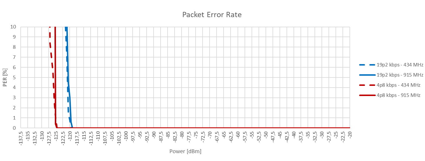
As a reference, packet error rate-based waterfall and frequency offset tolerance curves are provided in the following two figures for the 4.8 and 19.2 kbps PHYs in the 490 and 915 MHz bands.
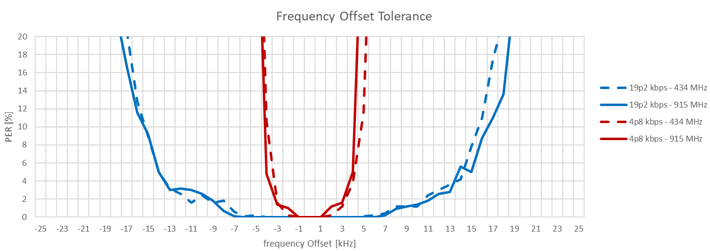
Note: In general, the expected tolerable frequency offset across LR PHYs, at 3 dB above sensitivity levels is +/- symbol rate in Hz. For example, the 4.8 kbps PHY should tolerate +/- 4.8 kHz frequency offset with wanted signal at 3 dB above sensitivity level. The required XO accuracy reflects this fact.