Calibrations#
To reach the maximum performance of the radio, you should enable and implement calibrations. In this document, we will talk about the details on how to enable and implement calibrations, when they can be avoided, and in what situations should they be implemented.
Enable All Calibrations#
Generally, you should enable all calibrations. They do have some drawbacks, and they can be avoided in some cases, but unless you're sure you don't need them, it's best to enable all of them.
If you open an example in Simplicity Studio, the RAIL initialization components will enable calibrations partially. However, the application still needs to implement the calibration callback:
if( events & SL_RAIL_EVENT_CAL_NEEDED ){
  sl_rail_calibrate(rail_handle, NULL, SL_RAIL_CAL_ALL_PENDING);
}
See the Event Handling and Automatic State Transitions tutorial if you're unsure how and where to use this code.
If you want to change this default "enable everything behavior", you can change them in the components RAIL Utility, Initialization (for image rejection and temperature calibration) and RAIL Utility, Power Amplifiers (for PA calibration). Alternatively, you can also call sl_rail_enable_pa_cal() and/or sl_rail_config_cal() in your application's init code.
In the following sections, we'll look into the 3 calibrations available on EFR32.
PA Calibration#
Why Is It Needed?#
The Power Amplifier (PA) has some part-to-part variations at low-power levels. To compensate this, Silicon Labs measures the PA during manufacturing and stores a few calibration constants on the DI page.
On Series 2 devices, PA calibration is enabled by default. On some devices, the API can be used to disable it, and on others, like on EFR32xG23, this API has no effect, and only exists for compatibility reasons.
On Series 1 devices, the 2.4 GHz Low Power PA is not affected by the PA calibrations.
When to Perform This Calibration?#
Call sl_rail_enable_pa_cal() before calling sl_rail_config_cal().
How Long Does It Take?#
Virtually no time. It's just loading some constants from the DI page, not an actual calibration.
What if I Don't Use It?#
When you set to transmit at low power, your output power might be different from part-to-part.
Are There Any Drawbacks?#
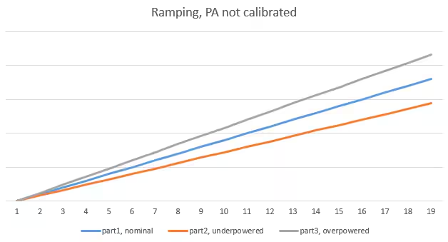
By default, during PA ramp-up, the radio ramps the PA current to a fixed value, which always takes the same time (but results to different power output).


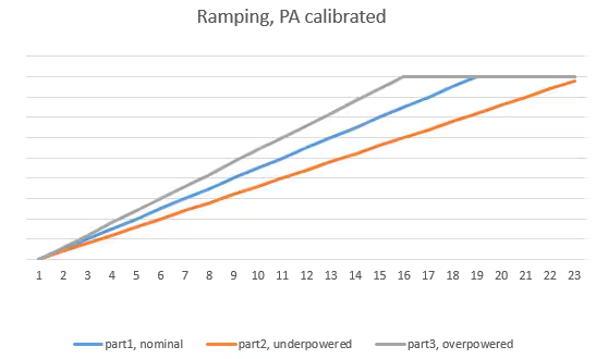
With calibration, the slope will be the same, but it can reach the target output power either faster or slower. To guarantee the scheduling timing, RAIL will set up the slowest ramp time as a delay for the ramp-up. This means that ramping will take slightly longer, and it might reach the top early.


Since we're talking about microseconds here, it's usually not an issue, unless for some reason, you need to be aware of ramping shape and time.
How to Do It?#
The simplest way is the implementation above.
Temperature Calibration#
Why Is It Needed?#
The Voltage Controlled Oscillator (VCO) must be temperature-compensated to generate the expected frequency. This will be performed automatically when the radio enters either the Tx or Rx state from idle, but it might be needed when the radio is in Rx for a long duration with big temperature changes.
When to Perform This Calibration?#
Generally speaking, when RAIL requests it through SL_RAIL_EVENT_CAL_NEEDED. RAIL will request calibration when the temperature changes by 70 °C.
How Long Does It Take?#
Under 100 µs.
What if I Don't Use It?#
There's no need for it if your device does not stay in Rx mode (without channel change), while the temperature can change by a lot.
If you don't calibrate when requested, your receiver frequency might change to the point where reception will be impossible.
Are There Any Drawbacks?#
It's not possible to receive packets while the calibration is running.
How to Do It?#
Call sl_rail_calibrate() or sl_rail_calibrate_temp() from the SL_RAIL_EVENT_CAL_NEEDED event if sl_rail_get_pending_cal() returns SL_RAIL_CAL_TEMP.
Image Rejection Calibration#
Also known as IR or IQ calibration.
Why Is It Needed?#
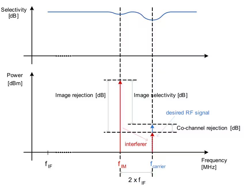
EFR32 implements a superheterodyne receiver, which fundamentally receives signals from two frequency bands: one IF (Intermediate Frequency) above the Local Oscillator (LO) frequency - wanted band, and one IF below the LO frequency
image band (the wanted band can be programmed to be below the LO, in which case image band is above the LO). Image band reception is not desired. It could cause reception issues if there's something on the image band, e.g. another channel or some completely different RF transmission.
The receiver is designed in a way that there is inherently suppression on the image band. The suppression of the image however can be further improved by performing an on-chip calibration. Note that the calibration does not improve receiver sensitivity, and it's not even used for Tx; it only improves signal suppression on the image frequency in Rx mode.


When to Perform This Calibration?#
Once, for each subGHz radio configuration, on each RF path, in the lifetime of the chip. This means it's enough to calibrate during manufacturing, store the result, and apply it later - but it has to be done on every part. In fact, we do this measurement for 2.4 GHz 802.15.4 and BLE and store it in the DI page of the chip. The internal calibration process is not available on 2.4 GHz, but the stored values are quite good for any radio configuration on that band. However, we can't provide calibration values for all the possible sub-GHz radio configurations.
How Long Does It Take?#
The calibration itself takes about 200 ms. Loading a stored value is just a register write, so it's nearly instantaneous.
What if I Don't Use It?#
You will be able to receive from the image frequency easier (i.e., sensitivity on the image band will be better, but very likely still not as good as on the wanted band). This can be harmful, for example if the image frequency is a neighboring channel.
Are There Any Drawbacks?#
Loading a stored value has no drawback. The calibration itself takes quite a long time, and it needs about 3 kB code memory (in Flex 3.0.2, with GCC 7.2.1, on Series 1). On EFR32xG23 and newer parts, it should need less code memory, as part of the algorithm is implemented in the hardware. However, it still needs about 2.3 kB (in Flex 4.3.1, with GCC 10.3.1).
How to Do It?#
The easiest way is the automatic implementation above. RAIL will request calibration when you call sl_rail_config_channels(). However, you can also trigger calibration manually, e.g., at boot.
There are a few more details that are important in multi-phy or multiprotocol environments. We will discuss it in the multiphy article.
IR calibration requires the radio Tx looped back to its Rx, and this cannot be easily done in some configurations. If all of these are true for you, please contact our support team on how to implement IR calibrations:
you have a Series 1 device (such as EFR32xG1/xG12/xG13/xG14)
the matching has split Tx/Rx configuration (practically in case of using FEM)
the target frequency is above 462 MHz
Related Variables in the Radio Configuration
IR Calibration is configured by a variable from rail_config.c, and the end
result is cached in a variable of rail_config.c For details, see the article
on the rail_config.c
file, specifically the
section IR Calibration helpers.
Using the Alternate APIs#
If you can use a "manufacturing test" firmware to run the IR calibration and store it, and only load the value from the end-product application, you can remove the significant code space required by the IR calibration by using the alternate API:
if( events & SL_RAIL_EVENT_CAL_NEEDED ){
  sl_rail_cal_mask_t pending = sl_rail_get_pending_cal(rail_handle);
  if ( pending & SL_RAIL_CAL_ONETIME_IR_CAL ){
    sl_rail_apply_ir_calibration(rail_handle, &stored_ir_value, SL_RAIL_ANTENNA_AUTO);
  } else { //if not IR, it must be temperature on EFR
    sl_rail_calibrate_temp(rail_handle);
  }
}
In the manufacturing firmware, you can use sl_rail_calibrate_ir() to get the IR calibration value. If you never call sl_rail_calibrate() or sl_rail_calibrate_ir() in your application, the calibration code will be removed freeing up code space.
IR Calibrations with Multiple RF Paths#
Some Series 2 devices (e.g., EFR32xG23) have an internal RF switch to support two RF paths.
With these parts, the above recommended APIs calibrate the antenna which was selected with the last parameter.
Antenna Diversity#
If you use the RF switch for antenna diversity, it is recommended to calibrate for both antennas, one by one:
sl_rail_calibrate_ir(rail_handle, NULL, SL_RAIL_ANTENNA_0);
sl_rail_calibrate_ir(rail_handle, NULL, SL_RAIL_ANTENNA_1);
Using
sl_rail_calibrate_ir()
with SL_RAIL_ANTENNA_AUTO is recommended on parts with internal switch, if you
do not want to use antenna diversity. This always calibrates the antenna
configured for use, so it is less error-prone.
Different Matching#
Another common usecase is to have multiple matching circuits (e.g., one for 433 MHz and another for 915 MHz) on the same device, and maybe also with an external switch to use the same antenna. In practice, you will use the two paths with different PHYs.
In this case, it is recommended to rely on RAIL's storage of calibration values for multi-PHY configs (see the Multi-PHY article for more details). However, you have to be careful to select the right matching and antenna for the given PHY before performing the calibration with sl_rail_calibrate() or sl_rail_calibrate_ir().
Stack-Specific IR Calibration#
Bluetooth Low-Energy and OpenThread#
Since BLE and OpenThread operate on the 2.4 GHz band, as it was described above, IR calibration is performed by applying the calibration value from the DI page.
Zigbee#
In case of the Zigbee, the IR calibration is performed at one time, once the radio starts using a band (2.4 GHz, 863 MHz or 915 MHz) first time from the last boot.
On 2.4 GHz band it is a simple memory write. On sub-GHz bands the IQ calibration differs on different device generations:
EFR32xG1 ICs are supplied with the proper calibration stored in the DI page, similarly to the 2.4 GHz band calibration.
All other parts run IR calibration when the device starts using these bands, and the results are retained until reboot.
Z-Wave#
The calibration in the Z-Wave stack is done automatically, during PHY load, implemented in the stack.
