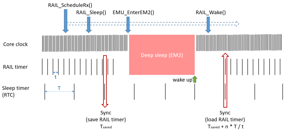
Timer Synchronization and Sleep#
Why Timer Synchronization is Needed#
RAIL internal timebase provides timing used for both timestamping and scheduled transmit/receive operations. However, since the hardware timer from which the RAIL timebase is derived from is the chip's high frequency oscillator (HFXO), it is therefore not available in deep sleep mode (EM2 and lower).
Additionally, the RAIL timebase cannot be derived from a low frequency oscillator as the resolution they provide isn't sufficient. However, accuracy is only required in active transmission or reception. When the radio transceiver is inactive, which is the case in low power energy modes, low frequency clock accuracy is accurate enough. This raises the problem of high frequency/accuracy time base recovery, which is necessary for radio functions when waking up from deep sleep modes.
A mechanism allowing clock conversion from low to high frequency clock domain can be used to recover the radio transceiver timebase. It involves one of the EFR32's Real Time Counter (RTC) which is a hardware timekeeping feature that remains functional in EM2. The RAIL driver software makes sure the low and high frequency time domains are kept synchronized.
Synchronization between high and low frequency clock domain isn't a trivial problem: the typical frequency of the RTC is 32.768 kHz, which indicates a 30 µs resolution (and it might be much worse if RTC is prescaled). If we save the value of both timers at the same time, we immediately have up to 30 µs error, and the same error again when we restore the RAIL timebase. That can amount to 60 µs in some cases, which is catastrophic for highly time sensitive protocols like BLE. For example, the BLE Inter-Frame Space (IFS) is 150 µs for indication, so 60 µs represents 40% timing error.
The solution to that problem is to save/restore the RAIL timer when the RTC timer ticks. This way, the worst case error is twice the RAIL timer resolution, which is 0.5us/2us, depending on the hardware (2us for EFR32xG1, 0.5us for all others).
Note: This refers to the hardware timer used to generate the RAIL timebase. The resolution of the RAIL timebase itself is 1us for all Series 1 and 2 chip except for the EFR32xG1 family that has a resolution of 2us (same as the hardware timer it relies on).
Implementation in RAIL#
Not only RAIL synchronizes the RAIL and RTC timers before entering deep sleep and after wakeup. It also uses RTC compare to set up an interrupt, which will wake up the MCU for the next radio operation (a PRS channel is reserved for this purpose).
If RAIL has been configured to use the power manager, calling sl_rail_init_power_manager() at initialization will automatically perform timer synchronization if the EM transitions is performed by the power manager. Calls to sl_rail_sleep() and sl_rail_wake() are unsupported in such a scenario. Power manager support in RAIL can be terminated by calling the sl_rail_deinit_power_manager() routine.
The following steps indicate how the functionality works:
The application code start by callingsl_rail_init_power_manager() and sl_rail_config_sleep() during init.
The application code schedules a radio operation (e.g. scheduled Tx). RAIL requests EM2 from power manager.
The power manager decides to enter EM2, and notifies all modules that need it, including RAIL.
RAIL synchronizes its hardware and the RTC timers.
RAIL sets up an RTC timer interrupt to trigger before the already set RAIL timer corresponding to the scheduled RX would trigger.
RAIL internal hardware timer is turned off.
The chip enters EM2 sleep.
RTC wakes up the MCU.
The power manager restarts the main oscillator and other required clocks. 10. The power manager notifies all modules that need it, including RAIL that the chip is returned from EM2. 11. RAIL synchronizes the timers. 12. RAIL timer is turned back on. RAIL requests EM1 from the power manager as we're close to the scheduled radio operation.


Note that the internal RAIL hardware timer is still needed to start the actual radio operation, so step 11 must be finished before the RAIL timer should be turned back on. This means RAIL must know the time it takes to perform steps 8-11, and set the RTC timer earlier by this amount, to guarantee that the RAIL timer is running by the time the radio operation must start. This time must be identified by the application if power manager is not being used.
Calling the
sl_rail_config_sleep()
routine before the first synchronization is mandatory for timer synchronization:
this function enables (SL_RAIL_CONFIG_TIMERSYNC_ENABLED) or disables
(SL_RAIL_CONFIG_TIMERSYNC_DISABLED) timer synchronization in RAIL, depending
on the sl_rail_sleep_config_t value in the sl_rail_timer_sync_config_t
argument. This will be handled internally by the power manager. With this
argument the used RTCC and PRS channel can also be specified. The set of the
available RTC timers varies on different chip families. You can select the
appropriate RTC timer in the Sleep Timer component's configuration. The default
values are:
PRS channel 7
A platform specific RTC (Usually ProRTC, if not available, compare channel 0 of RTC/RTCC)
It is recommended to use the power manager driven synchronization mechanism. However, if you are interested in using low energy modes without using the power manager, you can visit the old RAIL Tutorial: Timer Synchronization and Sleep article or the examples codes provided in docs.silabs.com.
Prerequisites#
For the operations above, RAIL needs:
The RTC timer should be free to use (for the synchronization).
An RTC compare channel should be free to use (for waking up the MCU).
A PRS channel is needed (so the synchronization can happen exactly when the RTC ticks).
The RTC timer is automatically initialized and the synchronization is
managed by the Sleep Timer service component, while the Power Manager
component handles the EM transitions when it is possible.
Series 2 parts have a dedicated RTC timer for this purpose.
