BLE Packet Error Rate#
Introduction#
This application demonstrates how to configure the necessary parameters to start transmitting or receiving BLE PER packets.
Setting Up#
To use this application, the following hardware, software and project setup is required.
Hardware Requirements#
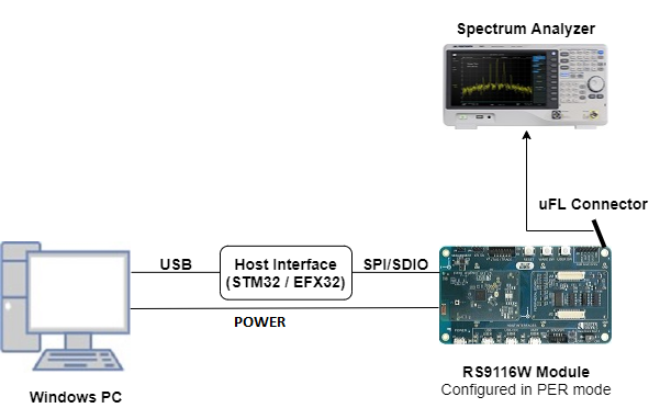
Windows PC with Host interface (UART / SPI / SDIO).
Silicon Labs RS9116 Wi-Fi Evaluation Kit
Host MCU Eval Kit. This example has been tested with:
Silicon Labs WSTK + EFR32MG21
Silicon Labs WSTK + EFM32GG11
Spectrum Analyzer and/or Power Analyzer

Software Requirements#
Embedded Development Environment
For Silicon Labs EFx32, use the latest version of Simplicity Studio
For STM32, use licensed Keil IDE
Application Build Environment#
Platform#
The application is designed to run on any one of the following host platforms
Host Interface#
By default, the application is configured to use the SPI bus for interfacing between host platforms EFR32MG21 or STM32F411 Nucleo and RS9116W EVK.
The application may also be configured to use the SDIO bus for interfacing between the host platform EFM32GG11 and RS9116W EVK.
Project Configuration#
The Application is provided with the project folder containing Simplicity Studio and Keil project files.
Simplicity Studio
The Simplicity Studio project is used to evaluate the application on EFR32MG21.
EFR32 Host Platform
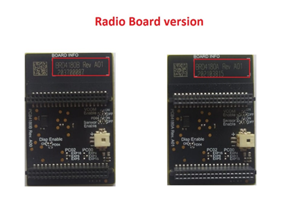
If the radioboard is BRD4180A or BRD4181A, then access the path
<SDK>/examples/featured/ble_per/projects/ble_per-brd4180a-mg21.slsprojIf the radioboard is BRD4180B or BRD4181B, then access the path
<SDK>/examples/featured/ble_per/projects/ble_per-brd4180b-mg21.slsprojThe radioboard version is shown in the following image

EFM32GG11 Host Platform
The Simplicity Studio project is used to evaluate the application on EFM32GG11.
Project path
<SDK>/examples/featured/ble_per/projects/ble_per-brd2204a-gg11.slsproj
Keil Project
The Keil project is used to evaluate the application on STM32.
Project path:
<SDK>/examples/featured/ble_per/projects/bt_per-nucleo-f411re.uvprojx
Bare Metal/RTOS Support#
This application supports bare metal and RTOS environment. By default, the application project files (Simplicity Studio and Keil) are provided with bare metal configuration.
Application Configuration Parameters#
The application can be configured to suit your requirements and development environment. Read through the following sections and make any changes needed.
Modifications to rsi_ble_per.c#
Transmit mode
  #define RSI_CONFIG_PER_MODE  RSI_BLE_PER_TRANSMIT_MODE
  #define BLE_TRANSMIT_CMD_ID  0x13
Receive mode
  #define RSI_CONFIG_PER_MODE  RSI_BLE_PER_RECEIVE_MODE
  #define BLE_RECEIVE_CMD_ID   0x14
Payload type
  #define DATA_PRBS9                  0x00
  #define DATA_FOUR_ONES_FOUR_ZEROES  0x01
  #define DATA_ALT_ONES_AND_ZEROES    0x02
  #define DATA_PRSB15                 0x03
  #define DATA_ALL_ONES               0x04
  #define DATA_ALL_ZEROES             0x05
  #define DATA_FOUR_ZEROES_FOUR_ONES  0x06
  #define DATA_ALT_ZEROES_AND_ONES    0x07
Channel type
  #define LE_ADV_CHNL_TYPE  0   // Advertising channel
  #define LE_DATA_CHNL_TYPE 1   // Data channel
Transmit Packet Length
#define BLE_TX_PKT_LEN 32 // Length of Tx packet [0 .. 255]Channel numbers
  #define BLE_RX_CHNL_NUM  10   // Receive channel number [0 .. 39]
  #define BLE_TX_CHNL_NUM  10   // Transmit channel number [0 .. 39]
BLE PHY Rate
  #define LE_ONE_MBPS        1
  #define LE_TWO_MBPS        2
  #define LE_125_KBPS_CODED  4
  #define LE_500_KBPS_CODED  8
  #define BLE_PHY_RATE       LE_ONE_MBPS
Scrambler seed
#define SCRAMBLER_SEED 0 // Seed for whitening. 0 = disable whitening.Transmit Mode
   #define BURST_MODE       0
   #define CONTINUOUS_MODE  1
   #define TX_MODE          BURST_MODE
Hopping Type
  #define NO_HOPPING      0
  #define FIXED_HOPPING   1
  #define RANDOM_HOPPING  2
  #define HOPPING TYPE    NO_HOPPING
Antenna select
  #define ONBOARD_ANT_SEL  2
  #define EXT_ANT_SEL      3
  #define ANT_SEL          EXT_ANT_SEL
RF Type
   #define BLE_EXTERNAL_RF  0
   #define BLE_INTERNAL_RF  1
   #define RF_TYPE          BLE_INTERNAL_RF
RF Chain
  #define NO_CHAIN_SEL       0
  #define WLAN_LP_CHAIN_BIT  1
  #define BT_HP_CHAIN_BIT    2
  #define BT_LP_CHAIN_BIT    3
  #define RF CHAIN           BT_HP_CHAIN_BIT
PLL Mode
  #define PLL_MODE_0  0
  #define PLL_MODE_1  1
  #define PLL_MODE    PLL_MODE_0
Loopback Mode
  #define LOOP_BACK_MODE_DISABLE  0
  #define LOOP_BACK_MODE_ENABLE   1
  #define LOOP_BACK_MODE          LOOP_BACK_MODE_DISABLE
Memory Usage Requirements
#define BT_GLOBAL_BUFF_LEN 15000 // The number of bytes required by the application and driverModifications to rsi_ble_config.h#
Modifications are not needed to run this example, the following is for informational purposes only.
   #define RSI_BLE_PWR_INX           30
   #define RSI_BLE_PWR_SAVE_OPTIONS  BLE_DISABLE_DUTY_CYCLING
Opermode command parameters
   #define RSI_FEATURE_BIT_MAP             FEAT_SECURITY_OPEN
   #define RSI_TCP_IP_BYPASS               RSI_DISABLE
   #define RSI_TCP_IP_FEATURE_BIT_MAP      TCP_IP_FEAT_DHCPV4_CLIENT
   #define RSI_CUSTOM_FEATURE_BIT_MAP      FEAT_CUSTOM_FEAT_EXTENTION_VALID
   #define RSI_EXT_CUSTOM_FEATURE_BIT_MAP  0
Testing the Application#
Loading the RS9116W Firmware#
See Getting started with PC to load the firmware into RS9116W EVK. The firmware binary is located in the directory <SDK>/firmware/
Building the Application on the Host Platform#
EFX32 Platform
Refer to EFx32 Getting Started, to setup EFR32 & EFM32 host platforms.
Import the EFR32/EFM32 project from
<SDK>/examples/eatured/ble_per/projectsSelect the appropriate
.slsprojproject file to suit your EFRx32 radioboard OR select the*.brd2204a-gg11.slsprojproject for the EFM32GG11 board.
Compile and flash the project to the EFx32
Debug the project and pause execution
If the RS9116W reset pin is NOT connected to the EFx32, press the RS9116W EVK Reset button
Free run the project
Proceed to Verifying Operation
STM32 Platform
Refer to STM32 Getting Started
Open the project
<SDK>/examples/featured/ble_per/projects/ble_per-nucleo-f411re.uvprojxin Keil IDE.Build and Debug the project, pause execution
If the RS9116W reset pin is NOT connected to the STM32, press the RS9116W EVK reset button
Run the project on the STM32
Proceed to Verifying Operation
Verifying Operation#
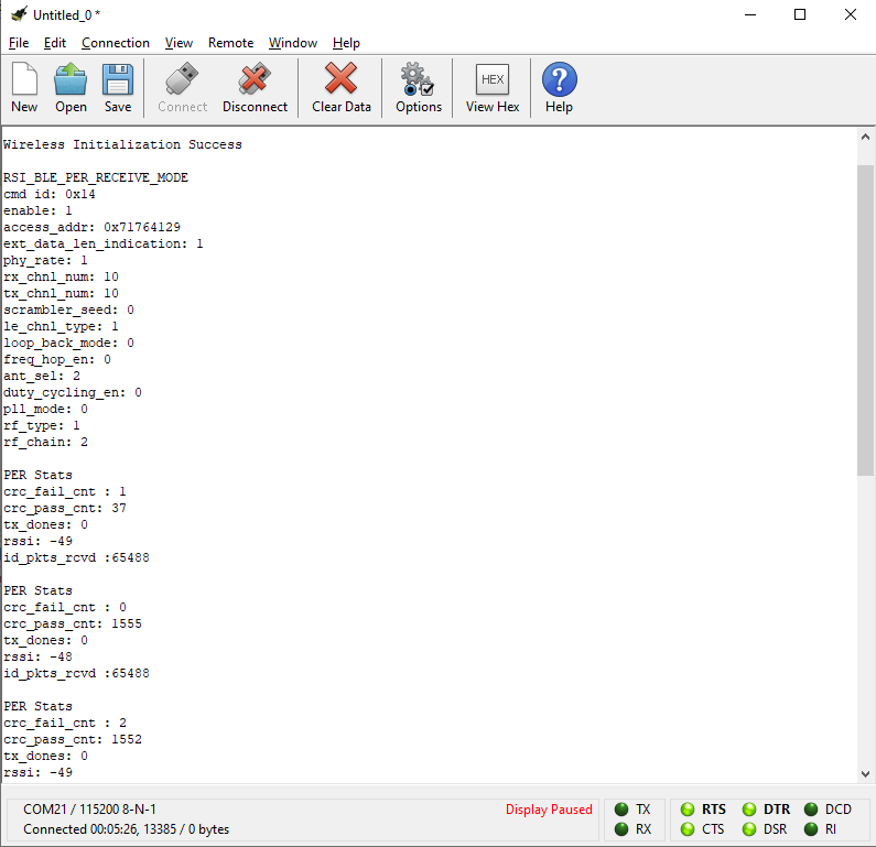
A terminal output shows the following text during receive testing. Receive PER statistics are regularly printed to the terminal.

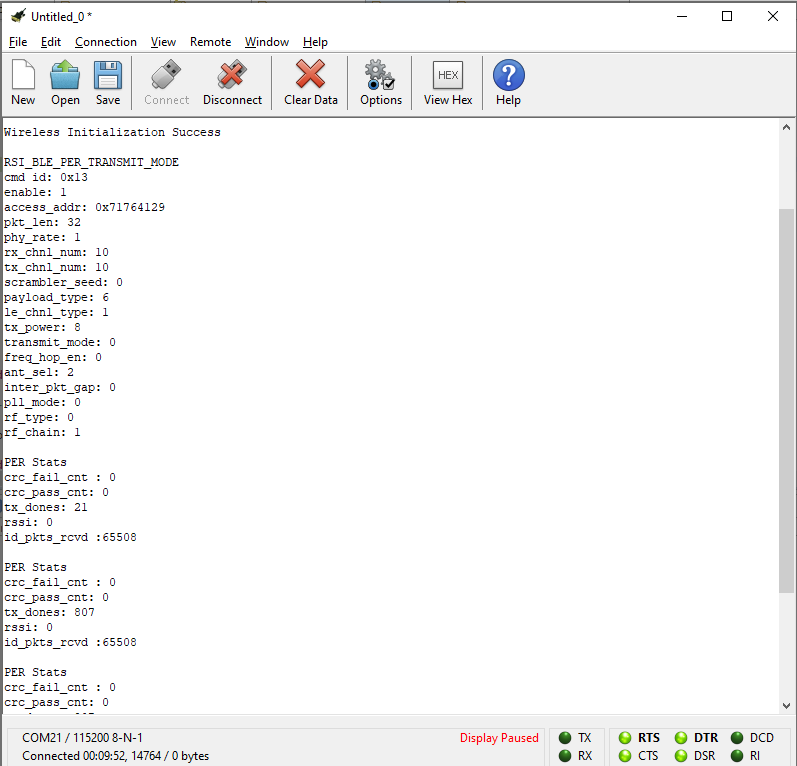
A terminal output shows the following text during transmit testing.

When transmitting, a spectrum analyser may be used to see transmitted packets (and the transmit spectrum) as shown in the following image.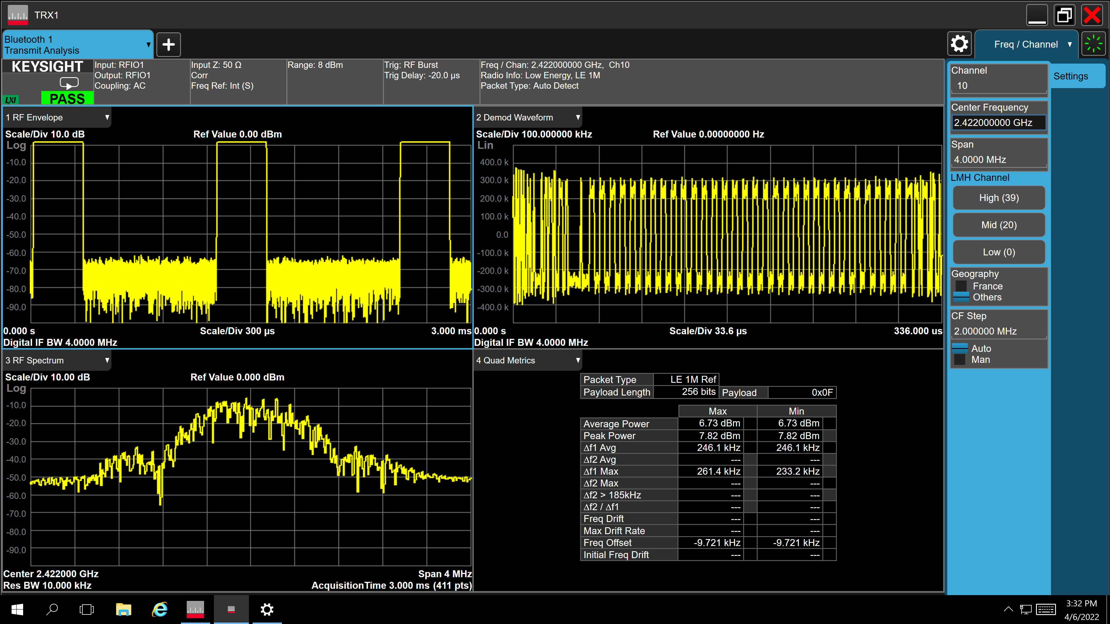

Compressed Debug Logging#
To enable the compressed debug logging feature please refer to Logging User Guide
