Sample Applications#
The sample setup consists of two types of applications, the Initiator and the Reflector. The setup uses the two-way ranging scenario. This is a connection-based measurement method where the Initiator scans for the Reflector and connects to it. After a connection is established, both the Initiator and Reflector send signals and packets to measure phase and time. The Reflector sends the measured phase and time back to the Initiator using GATT service and characteristics. The Initiator then combines all the information to calculate distance.
The Simplicity SDK (SiSDK) provides sample projects for the CS Initiator and CS Reflector devices that can be run in two modes of operation—SoC Mode and NCP Mode.
The sample projects for EFR32xG24 device can be found in SSv5.
SoC Mode Sample Applications#
In SoC mode, the Bluetooth stack and the application (including the RTL library) run on the SoC/EFR32xG24 device. SiSDK provides the following two Studio sample projects supporting this mode of operation.
bt_cs_soc_initiator: Bluetooth – SoC CS Initiator
bt_cs_soc_reflector: Bluetooth – SoC CS Reflector
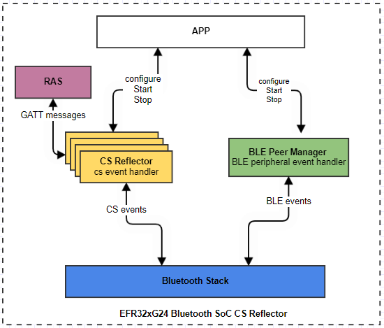
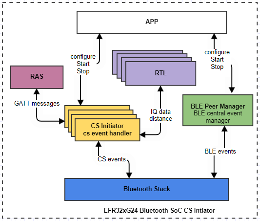
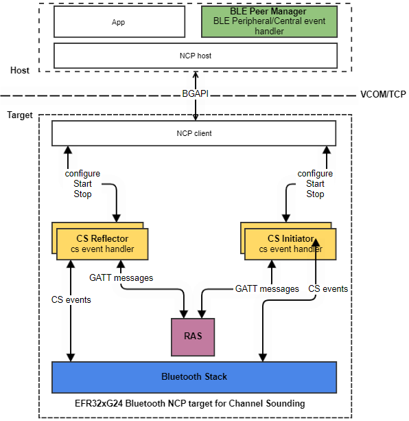
The applications consist of software components aimed at handling CS and general BLE activities and interfacing with the RTL library to yield distance estimation. The diagram below depicts a high-level software architecture of the SoC CS Initiator and Reflector sample applications.
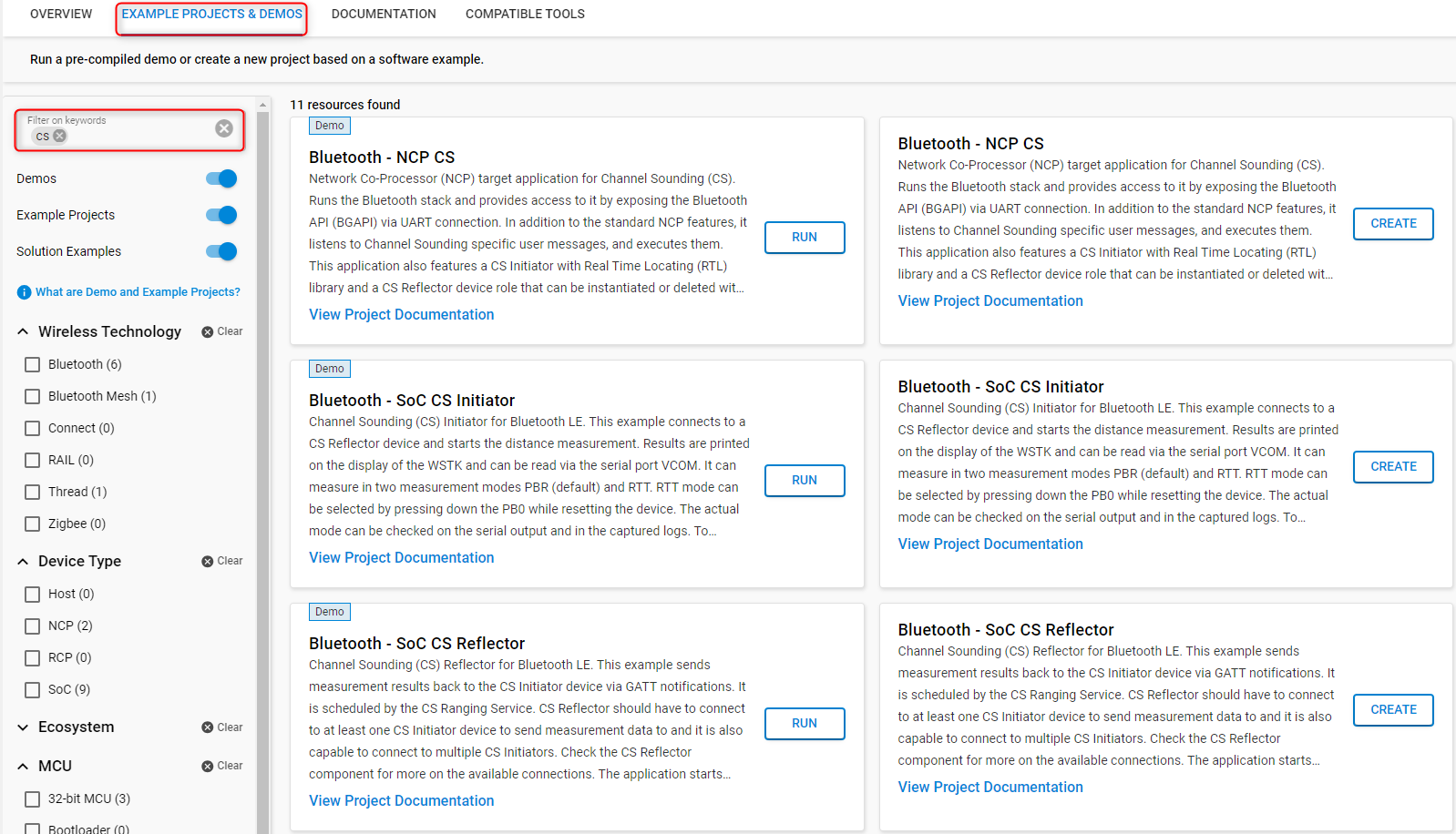
To access the projects in SSv5, in the Launcher perspective (1), select your device from the Adapter Debug window (2). In the Overview tab (3), choose the latest Simplicity SDK Suite, and then go to the EXAMPLE PROJECTS & DEMOS tab (5).

Once you are in the EXAMPLE PROJECTS & DEMOS tab, use the CS filtering keyword to see the sample applications. Click CREATE to create the project.
All the CS example projects supported on the BRD4198A and BRD2606A boards are also available as pre-built demos. For quick testing, you can run the demos by clicking RUN. This will flash the required bootloader and the corresponding sample application to your device.
Bluetooth – SoC CS Reflector#
The main software components of the Bluetooth SoC CS Reflector are:
BLE Peer Manager
CS Reflector
CS RAS
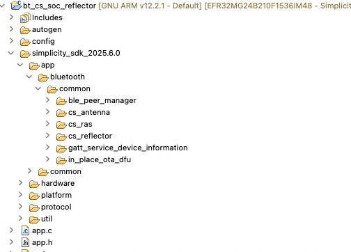
Project Walkthrough#
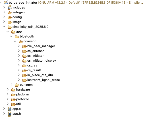
The project contains the C related files under the folder <SDK_Folder>/app/bluetooth/common/.
The BLE Peer Manager is responsible for implementing the GAP Peripheral roles of the Reflector device. These include configuring, starting, and stopping advertising. It accomplishes these tasks through the Bluetooth stack API calls: sl_bt_advertiser_set_timing(), sl_bt_legacy_advertising_start(), and sl_bt_advertiser_stop(), respectively. Before advertising is started, the advertising set is created, and the advertising data is generated using sl_bt_advertiser_create_set() and sl_bt_legacy_advertiser_generate_data(), respectively. These are done in the ble_peer_manager_peripheral.c file.
The CS Reflector component is responsible for setting the maximum CS transmission power and enabling the CS Reflector role on the device for a specific connection by calling the sl_bt_cs_set_default_settings() API. This component also handles CS related events: evt_cs_security_enable_complete, which indicates that the CS Security Enable procedure has completed, evt_cs_procedure_enable_complete, which indicates the start of the CS procedure by the Initiator, and evt_cs_result, which is triggered by the local controller when a new CS result is available. These are done in the cs_reflector.c file.
The CS RAS component is responsible for parsing RAS GATT messages and creating RAS GATT responses.
Usage#
Select the Bluetooth - SoC CS Reflector sample application, and build and flash it to a device. This sample application requires the bootloader-apploader type of bootloader.
After starting up, it should be advertising with the name CS RFLCT. By default, the Reflector allows up to 4 connections. This value can be changed in the Connection software component. In multiple connection use cases, it is advised to use a longer measurement interval.
Bluetooth – SoC CS Initiator#
The main software components of the Bluetooth SoC CS Initiator are:
BLE Peer Manager
CS Initiator
RTL library
CS RAS
Project Walkthrough#
The project contains the C related files under the folder <SDK_Folder>/app/bluetooth/common/.
The BLE Peer Manager is responsible for implementing the BLE central roles of the Initiator device. This includes configuring the scanning parameters, starting/stopping the scanner, and initiating/closing a connection with a Reflector device. It achieves these by calling the Bluetooth stack APIs: sl_bt_scanner_set_parameters(), sl_bt_scanner_start()/sl_bt_scanner_stop(), sl_bt_connection_open()/sl_bt_connection_close(), respectively.
The CS Initiator component is responsible for CS related activities. These include, setting the default parameters for CS transmission power and device role using sl_bt_cs_set_default_settings(), and ensuring that the requirements for starting a CS procedure are met.
Before a CS procedure is started:
The CS capability exchange procedure should take place. This is done by calling
sl_bt_cs_read_remote_supported_capabilities(). If no capability exchange has been initiated for the connection by the host and if there is no cached copy of the capabilities of the remote device, then the controller will initiate the CS capability exchange procedure.The connection between the peer devices must be encrypted. This is done by calling
sl_bt_sm_increase_security().The CS configuration is created and configured using
sl_bt_cs_create_config()andsl_bt_cs_set_procedure_parameters ()API calls, respectively.The CS security information is exchanged by calling
sl_bt_cs_security_enable(). The Deterministic Random Bit Generator (DRBG) is seeded from security information exchanged at this step.
After these steps, the CS procedure is started using sl_bt_cs_procedure_enable() API call.
The CS Initiator is also responsible for handling CS related events triggered by the local controller and providing the CS procedure data to the RTL library, which then calculates the distance. These are done inside cs_initiator.c file.
The CS RAS component is responsible for parsing RAS GATT messages and creating RAS GATT responses.
The RTL library is responsible for doing the actual distance estimation.
Usage#
Select the Bluetooth - SoC CS Initiator application, and build and flash it to the device. This sample application requires the bootloader-apploader type of bootloader.
On the BRD4198A board, the initiator will display the measured distance on the LCD mounted on the main board as shown below. The LCD display will also show the measurement mode, algorithm mode, raw distance, the likelihood of the measured value, and the RSSI based distance estimation. These calculated parameters are displayed for each reflector connection (up to 4).

The device will also send the distances via UART. Open a console application on the PC to see the logs:
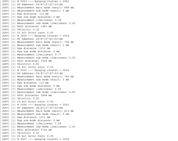
In the logs:
Ranging Counter: A counter that increments every time the ranging data is received by the RAS client. A mismatch between the CS procedure counter and the ranging counter can indicate that the procedures were aborted or other issues causing the measurements to fail.Measurement main mode result: The estimated distance value using CS in the main mode.Measurement submode result: The estimated distance value using CS in the submode, if enabled.Raw distance: The estimated distance value using CS in the main mode without post-filtering. The post-filtering removes any large undesired jumps in the distance reported.Raw submode distance: The estimated distance value using CS in the submode (if enabled) without post-filtering.Measurement likeliness: The probability that the CS distance estimate using main mode is correct. High values (close to 1) typically indicate accurate estimates, while low values (closer to 0) suggest a higher likelihood of error.Measurement submode likeliness: The probability that the CS distance estimate using submode (if enabled) is correct.RSSI distance: The RSSI based distance estimation.Velocity: Velocity estimate calculated from PBR measurements. Negative velocity indicates an approaching target. This metric is supported only in PBR real-time fast mode.CS bit error rate: The number of bit errors detected (valid only in RTT mode).
When there are multiple initiator instances to connect with multiple reflectors, the initiator instance that is tied to the reflector can be distinguished by the connection handle and the reflector's address. Note that the maximum number of connections supported by the initiator is 4, which is the default configuration (CS_INITIATOR_MAX_CONNECTIONS) in the SoC initiator example application.
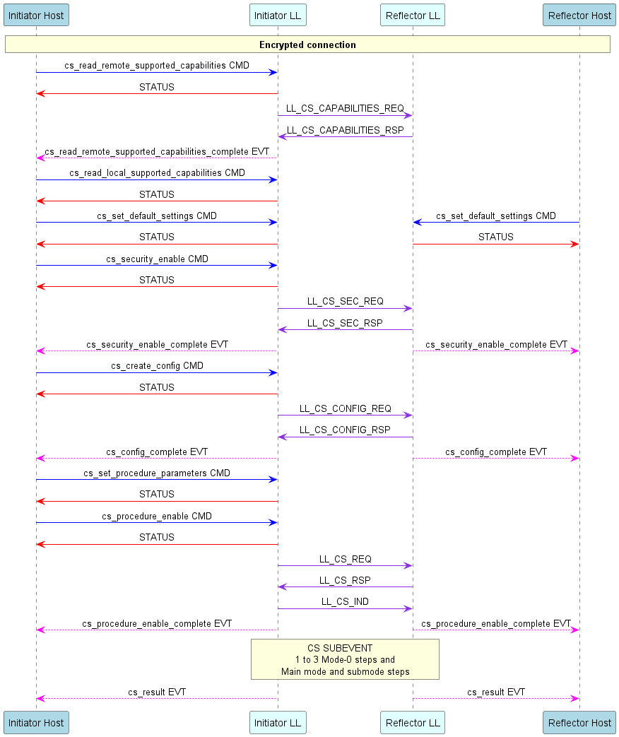
Channel Sounding Sequence Chart#
The following sequence diagram illustrates the message exchange between the Initiator and Reflector devices, based on the implementation of our sample applications. The diagram shows the BGAPI commands and events between the controller/LL and host of both devices, and the actual PHY PDUs exchanged between the Initiator and Reflector.
NCP Mode Sample Applications#
The Silicon Labs Bluetooth SDK also includes NCP sample applications that support channel sounding. In NCP mode, the EFR32xG24 device functions as NCP target or coprocessor, working with a host controller that functions as an NCP host. The NCP host and target communicate on a serial interface using the BGAPI protocol.
Starting with version 2024.6.0, a multi-role NCP architecture is introduced for channel sounding. This architecture allows running multiple instances with similar or different roles simultaneously. To realize this architecture, the Bluetooth SDK offers:
A Studio example project for NCP target (app/Bluetooth/example)
bt_cs_ncp: Bluetooth - NCP for Channel Sounding
A host example for the NCP host (app/Bluetooth/example_host)
bt_cs_host: supports the multi-role NCP host
In multi-role NCP architecture, the Bluetooth stack and RTL library are run on the SoC, whereas the application is run on the host machine.
Key features of the multi-role NCP architecture:
As the name suggests, this architecture allows multiple instances* to run with different CS roles; that is, Initiator and Reflector roles.
The Initiator and Reflector roles are integrated on the NCP target side. As a result, the host application can act as a Reflector, an Initiator, or both.
The distance estimation is done on the NCP target, and only the measurement results are sent to the host using CS specific BGAPI commands, thereby reducing the load on serial communication.
*Up to 4 simultaneous connections are supported. This means that the number of instances (Initiator and Reflector combined) cannot exceed 4.
NCP Interface#
The NCP provides a high-level interface to the host application. The host can configure, start a Reflector, or Initiator instance on the NCP target by calling sl_bt_user_cs_service_message_to_target().
Any asynchronous CS event triggers an sl_bt_evt_user_cs_service_message_to_host_id event on the host. The host then parses this event to extract the specific CS event, which can be:
CS result
CS Log data from RTL, Initiator, or Reflector
Error events
This occurs in app.c file of bt_cs_host project.
Building the Multi-Role NCP Projects#
For the target, in Simplicity Studio Launcher perspective, select the Bluetooth - NCP for Channel Sounding, and build and flash it to the board. This sample application requires the bootloader-uart-bgapi type of bootloader.
For the Host application, go to app\bluetooth\example_host\bt_cs_host. For testing purposes, you can build the application by simply calling $ make.
When you are developing, however, Silicon Labs recommends that you first generate the project using the export feature of the makefile. This feature allows copying all the SiSDK files that belong to the project into the export folder. After the project files are exported, the export directory will be your working directory that is completely detached from the SiSDK but has the same folder structure inside. With export, it is clear at glance which files belong to the project.
To generate your multi-role NCP host, open a terminal, go to app\bluetooth\example_host\bt_cs_host, and call the following command:
$ make export
A custom export folder can be also specified using the EXPORT_DIR variable.
$ make export EXPORT_DIR=/c/users/username/my_bt_cs_host
After generating the project, you can build it by:
Navigating to the exported project directory
$ cd /c/users/username/my_bt_cs_host/app/bluetooth/example_host/bt_cs_hostRunning the
$ makecommand
See the required tools and more information about building an NCP Host application here.
Running the Multi-Role NCP Host Application#
After the project is built, an executable file bt_cs_host.exe is generated inside the exe folder. Run the application using the following command:
$ ./exe/bt_cs_host.exe -t <tcp_address> | -u <serial_port> [-b <baud_rate>] [-f] [-l <log_level_filter>] [-m <cs_mode>] [-R <max_reflector_instances>] [-I <max_initiator_instances>] [-F <reflector_ble_address>] [-r] [-w] [-o] [-h]
Options | Description |
|---|---|
-t | Target TCP/IP connection parameters (if WSTK is connected via Ethernet). <address> IP address of the WSTK board. |
-u | Target USB serial connection parameter (if WSTK is connected via USB). <serial_port> COM port (Windows) or device file (POSIX) to be opened. |
Optional Parameters | Description |
-b | Baudrate can be given if the connection is established via serial port. <baud_rate> Baud rate of the serial connection (default: 115200). |
-f | Disable flow control (RTS/CTS), default: enabled |
-l | Application log level filter. <level>: Integer representing log level. 0: Critical. 1: Critical, error. 2: Critical, error, warning. 3: Critical, error, warning, info (default). 4: Critical, error, warning, info, debug. |
-m | CS main mode <cs_main_mode>: number corresponding to CS main mode, default: 2, PBR 1: RTT 2: PBR. |
-M | CS submode <cs_sub_mode>: number corresponding to CS submode, default: No sub mode 1: RTT 255: no submode Note: Only main mode = PBR, submode = RTT supported now |
-R | Maximum number of reflector instances. <max_reflector_instances>: 0 to 4 (default: 1). |
-I | Maximum number of initiator instances <max_initiator_instances>: 0 to 4 (default: 1). |
-F | Enable reflector BLE address filtering. <reflector_ble_address> e.g -F 68:12:EF:34:18:AB or 6812EF3418AB |
-w | Use wired antenna offset. |
-o | Object tracking mode, default: 0 <o> 0: Moving object tracking (up to 5 km/h). 1: Stationary object tracking. 2: Moving object tracking fast (REAL_TIME_FAST) |
-p | Pre-set parameters for channel map selection, default: 2 ( <p> 0: 1: 2: 3: |
-a | Antenna configuration index for antenna switching, default: 7 0 : Single antennas on both sides 1 : Dual antenna initiator & single antenna reflector 4 : Single antenna initiator & dual antenna reflector 7 : Dual antennas on both sides |
-q | Antenna usage for CS SYNC packets, default: 0xFE ( 1 : use antenna ID1 only 2 : use antenna ID2 only 0xFE : Switching between antennas for each channel |
-s | Optimized procedure scheduling <o> 0: Optimized for frequency update 1: Optimized for energy consumption 2: Custom Note: Default is frequency optimized procedure scheduling |
-T | Enable RTT trace including BGAPI messages and RTL log Note that the RTT blocks the target if no client is connected. |
-P | Use 1M connection PHY Note: Default is 2M |
-h | Displays the help menu. |

Code Size#
Compile-time code and memory allocation can be checked with arm-none-eabi-size and arm-none-eabi-objdump.
The following sizes were measured with the out-of-box CS applications:
Application | Flash (B) | Static RAM (B) | Heap Reservation (B) |
|---|---|---|---|
| 401,056 | 49,844 | 212,292 |
| 448,268 | 65,144 | 196,992 |
| 277,068 | 34,460 | 227,676 |
Flash = text+data (code and initialized data image). Static RAM = .data + .bss + .stack + RAM-resident code/data. Heap Reservation = reserved heap section size at compile time.
Run-time heap usage is use-case specific. To monitor application heap usage, refer to the Memory Manager API. For guidance on optimizing resource usage, see the respective application's README.
CPC Support#
The CS Initiator sample application also supports the CPC over NCP feature. For details about how to add the CPC interface to the project refer to Using NCP with CPC. This covers the basic setup of the host application on a standard Linux system. It is also possible to use OpenWRT based systems as a host. Contact Silicon Labs for a sample setup and instructions.