Single Locator Sample Application#
Locators are more complex than asset tags. They control an array of antennas rather than a single antenna, precisely sample incoming signals, and can optionally calculate angle values from the received signal. Because of the resource limitations of the EFR32, all locator sample applications supported in Bluetooth SDK v3.x use Network Co-Processor (NCP) mode. In this mode, the Bluetooth stack runs on the EFR32 (the NCP target), while the application runs on a host, such as a microcontroller (MCU) or PC.
The Bluetooth SDK v3.x provides one sample project for the EFR32 NCP AoA locator target (Bluetooth AoA - NCP locator) and one sample app for a locator host (bt_aoa_host_locator). The NCP target and host sample project can be found in Simplicity Studio.
The NCP AoA locator application is common to all variants, including connection-based, connectionless, and Silicon Labs proprietary modes. However, configure the locator host with the appropriate CTE mode at runtime.
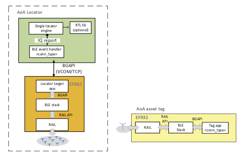
The physical interface between the AoA locator host and the NCP AoA locator can use either a virtual COM port over USB (VCOM) or TCP/IP. When using TCP/IP, the WSTK and antenna board can be physically separated from the host, provided the host can reach the NCP AoA locator by using its IP address.
NCP AoA Locator Sample Application#
The Bluetooth SDK v3.x provides the Bluetooth AoA - NCP locator example project to support an NCP AoA locator that can receive and sample CTEs transmitted by asset tags.
The NCP AoA locator (EFR32) is responsible for:
Running the Bluetooth stack
Enabling the CTE receiver feature
IQ sampling
Antenna switching
Mirroring the BGAPI interface to UART
The CTE receiver feature is enabled automatically by installing the AoA Receiver components, which is default in the Bluetooth AoA - NCP locator project.
Also, the Bluetooth AoA - NCP locator project has two main additional components:
Periodic Advertising Synchronization: enables the periodic advertising synchronization feature.
RAIL Utility, AoX: supports antenna pin configuration.
To test the NCP AoA locator application:
Create Bluetooth AoA - NCP locator project in Simplicity Studio 6.
Build the project.
Flash it to an EFR32xG22 device with an antenna array (that is, to a Silicon Labs Direction Finding board).
The sample does not contain a bootloader. By default, a new device is factory-programmed with a bootloader. If you have a new device, haven’t cleared the bootloader region for your part or have a supported bootloader image already flashed on your device, you do not need to flash a bootloader. Once you have installed a bootloader image, it remains installed until you erase the device. If you need to load a bootloader, select an example, such as SPI Flash Storage Bootloader (single image), and build it and flash it as described above. For more information about the Gecko Bootloader, see Silicon Labs Gecko Bootloader User’s Guide for GSDK 4.0 and Higher (series 1 and 2 devices) or Silicon Labs Gecko Bootloader User’s Guide for Series 3 and Higher.
Single AoA Locator Host Application#
The AoA locator host application is responsible for:
Controlling the stack, for example to find tags, connect to them, sync on periodic advertisings, and so on.
Initializing a buffer for IQ samples, and receiving the IQ samples from the stack.
Using the RTL library to calculate angles from the IQ samples (optional).
Publishing of angle/IQ reports, and subscription of config and correction topics to the MQTT broker.
The AoA locator relies on several software components to accomplish the above-mentioned tasks. The main software components that characterize the operation of the AoA locator are aoa_angle and aoa_cte. The aoa_angle software component is responsible for feeding the raw IQ samples to the RTL library and calculate the angle values. On the other hand, the aoa_cte component handles the implementation of different CTE receiving modes—connection, connectionless, and Silabs modes. The type of CTE mode can be set at runtime via MQTT, without recompiling or restarting the application manually.
Connection Based CTE Receiving Locator Host#
In a connection based CTE mode, the locator must:
Find a connectable advertising tag with a CTE service.
Connect to the asset tag.
Discover the GATT database.
Enable CTE using the Constant Tone Extension Enable characteristic.
Send a CTE request and receive a CTE response.
Collect and convert IQ samples into common IQ report format.
Once the IQ report is available, the angle is calculated and published to the MQTT broker using the aoa_cte_on_iq_report() callback.
In the background, the aoa_cte_on_iq_report() calls the aoa_calculate() API, which leverages the RTL library to calculate the angle. The angle data is then published to the MQTT report by calling mqtt_publish().
Connectionless CTE Receiving Locator Host#
CTEs can also be received in connectionless mode using Bluetooth periodic advertisements. In this case, the locator must:
Find the asset tag with a CTE service by its advertisement.
Sync on the periodic advertisement.
Enable CTE receiver in connectionless mode using periodic advertising.
Collect and convert IQ samples into a common IQ report format.
Once the IQ report is available, the angle is calculated and published to the MQTT broker using the aoa_cte_on_iq_report() callback.
In the background, the aoa_cte_on_iq_report() calls the aoa_calculate() API, which leverages the RTL library to calculate the angle. The angle data is then published to the MQTT report by calling mqtt_publish().
Silabs Proprietary CTE Receiving Locator Host#
CTEs can also be received in extended advertising using Silabs mode. In this approach, the locator must:
Find the asset tag by its advertisement.
Enable receiving CTE in Silicon Lab’s enhanced mode.
Collect and convert IQ samples into common IQ report format.
Once the IQ report is available, the angle is calculated and published to the MQTT broker using the aoa_cte_on_iq_report() callback.
In the background, aoa_cte_on_iq_report() calls the aoa_calculate() API, which uses the RTL library to calculate the angle. The resulting angle data is then published to the MQTT report by calling mqtt_publish().
Building the Single AoA Locator Host Sample Application#
Building AoA Locator on Windows#
Currently, MinGW-w64 is the only supported build environment on Windows. The makefiles make sure that the gcc is used with a proper prefix (x86_64-w64-mingw32-). The recommended build environment on Windows is MSYS2.
Download and install MSYS2: https://www.msys2.org/.
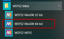
Open the Mintty bash. Make sure to start Mingw-w64 64 (mingw64.exe) when launching Mintty. 32-bit versions of MYSYS2 will not work.
Install
gcc.pacman -S make mingw-w64-x86_64-gccInstall mosquito library with the same prefix as the
gcc.pacman -Sy mingw-w64-x86_64-mosquitto
To build the project:
Create a new Bluetooth AoA - Host Locator project in Simplicity Studio 6
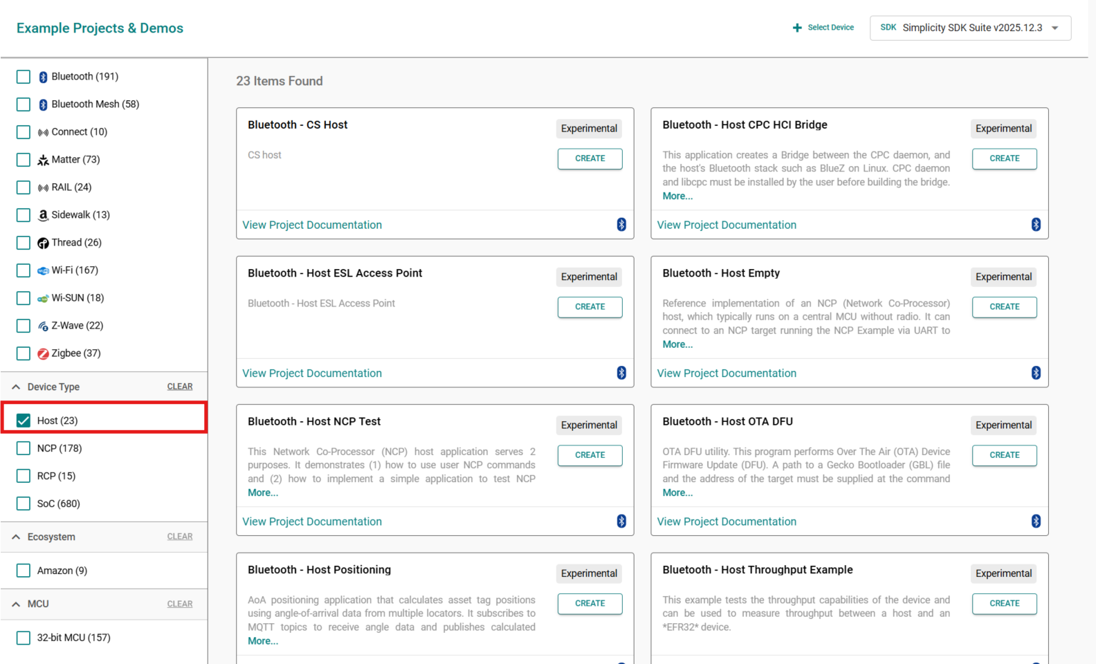
At the Target Device select the option Part and WIN32
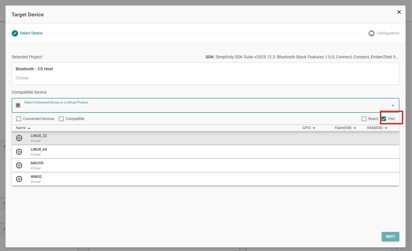
Build the project
make -f bt_aoa_host_locator.MakefileThe build output is created in a new build/debug/ folder.
Building AoA Locator on Linux#
The RTL library is built for Ubuntu 18 LTS 64-bit. The makefile is written so that it recognizes the Linux environment and automatically uses the Linux version of the RTL library.
To build the project:
Install mosquitto library if it’s not installed yet.
sudo apt install libmosquitto-dev
To build the project:
Create a new Bluetooth AoA - Host Locator project in Simplicity Studio 6
At the Target Device select the option Part and LINUX
Build the project
make -f bt_aoa_host_locator.MakefileThe build output is created in a new build/debug/ folder.
Building AoA Locator on Embedded Linux#
Create a new Bluetooth AoA - Host Locator project in Simplicity Studio 6
At the Target Device select the option Part and the LINUX
At section With Project Files select Copy contents and for Target IDE select Makefile(GCC)
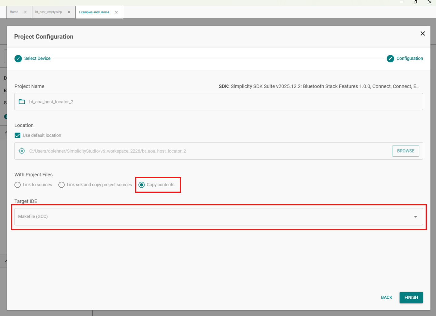
Change the compiler to the desired one in the makefile or copy exported GSDK files to the home folder of the target Cortex-A device (for example, Raspberry Pi).
scp -r bt_aoa_host_locator pi@raspberrypi.local:~
Additional steps in case of copy:
Start SSH connection with Raspberry Pi.
ssh pi@raspberrypi.localInstall mosquitto libraries if it's not installed yet.
sudo apt install libmosquitto-devChange to the project folder
cd ~/bt_aoa_host_locatorBuild the project using the make command.
AoA Locator Configuration#
The AoA locator configuration is an important step in angle estimation. The host application, of course, can be started without a configuration when using the default settings with Silicon Lab’s dual polarized antenna board (i.e BRD4191A). In all other cases, modifying the configuration before or during runtime becomes mandatory.
The SDK host example project provides a template JSON config file locator_config.json inside the config folder of the sample app in the SDK bluetooth_le_app\example_host. The host application can parse the config JSON passed through CLI input. The file has a simple JSON format containing key/value pairs of different configuration option, including the antenna type (mode), CTE configuration, angle estimation parameters, the allowed list of tags, and angle masks. The following shows a prototype configuration for a single locator:
{
"version":1,
"aoxMode":"SL_RTL_AOA_MODE_REAL_TIME_BASIC",
"antennaMode":"SL_RTL_AOX_ARRAY_TYPE_4x4_DP_URA",
"antennaArray":[
0,
1,
2,
3,
4,
5,
6,
7,
8,
9,
10,
11,
12,
13,
14,
15
],
"angleFiltering":true,
"angleFilteringWeight":0.6,
"angleCorrectionTimeout":5,
"angleCorrectionDelay":3,
"cteMode":"SILABS",
"cteSamplingInterval":3,
"cteLength":20,
"slotDuration":1,
"reportMode":"ANGLE",
"allowList":[
"ble-pd-AAAAAAAAAAAA",
"ble-pd-BBBBBBBBBBBB"
],
"azimuthMask":[
{
"min":0.0,
"max":10.0
},
{
"min":20.0,
"max":30.0
},
{
"min":40.0,
"max":50.0
}
],
"elevationMask":[
{
"min":0.0,
"max":10.0
},
{
"min":20.0,
"max":30.0
},
{
"min":40.0,
"max":50.0
}
]
}Antenna Mode#
The antennaMode specifies the type of antenna array board supported by the RTL library. The default antenna type is SL_RTL_AOX_ARRAY_TYPE_4x4_DP_URA — Silicon Lab’s 4x4 dual polarized antenna array (i.e BRD4191A). Refer to the API reference manual for all other antenna types/modes supported by the RTL library.
Antenna Array#
The antennaArray defines the antenna switching sequence according to the antenna numbers shown on the board, with index starting from 0. To understand the relation between the antenna switching sequence and the board’s pin logic, refer to A Silicon Labs Dual Polarized Antenna Array Board (BRD4191A).
CTE Mode#
The cteMode determines the type of CTE receiving mode of the locator. The default CTE mode is SILABS. To track asset tags transmitting CTE in other modes, you must set the value of this config parameter accordingly. Set this attribute to:
CONN for connection based CTE mode.
CONN_LESS for connectionless CTE mode.
SILABS for Silicon Labs proprietary CTE mode.
Report Mode#
The reportMode determines whether the host application calculates angle or publishes the raw IQ data received from the NCP target directly to the MQTT broker. The default report mode is ANGLE.
The report mode is an important configuration parameter especially if you want to use your own custom algorithm to calculate angle from raw IQ data. In this case, enable IQ sample report mode using IQREPORT value for this parameter.
Allowed List#
The allowList tells the locator the list of asset tags to track. This improves the performance of the system by searching only asset tags that are only in the list.
Note that the template config JSON file has pseudo addresses of tags for the allowed list. If you start the host application using the config option, please make sure that you have modified the list with the right addresses of your tags. You can also empty the “allowList” like below to track every tag that the locator can find.
"allowList":[
]Angle Masks#
The azimuth and elevation masks in the locator’s config file tell the estimator in which range NOT to search for the tag. For instance, if a locator is next to a wall, and the asset tag is to be searched in the room, then the locator should look for an azimuth Angle of Arrival in a 180° range instead of a 360° range. Similarly, if the locator is in the corner, it may be enough to search in a 90° angle range only. This improves both reliability and computation time. When the azimuth and elevation masks are configured, the RTL lib will set the weighting of the angle values inside the masked region to zero and will not return values inside the masked region. Instead, it chooses the next highest value outside the masked region. A locator may have more than one angle masks, for both azimuth and elevation.
The azimuth and elevation masks are independent of the coordinate system and are related to angle directions of each individual boards. 0°, 45°, 90°, 135°, 180°, -135°, -90°, and -45° directions are indicated on the antenna array board. Once you place the board, you can easily tell in which direction you want to search for the tag. Consider the following setup where the blue area is the desired tracking space. The red lines on the locators indicate the masked regions where the estimator will not search for the tag.
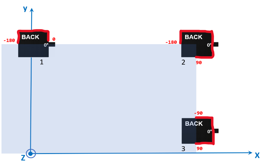
For this setup, the config files for each locator should look like the following:
config_locator1.json
{
"azimuthMask": {
"min": -180.0,
"max": 0.0
}
}config_locator2.json
{
"azimuthMask": {
"min": -180.0,
"max": 90.0
}
}config_locator3.json
{
"azimuthMask": {
"min": -90.0,
"max": 90.0
}
}Note that the template config JSON file contains a range of azimuth and elevation angle mask values. If you start the host application using the config option, please make sure that you have modified the values according to your need. You can also empty the arrays as below to track the tags on a full range.
"azimuthMask":[
],
"elevationMask":[
]Angle Correction Time Out and Angle Correction Delay#
These parameters control the logic for how long the corrections from the angle feedback feature of the positioning host last after issuing one. Refer to Running the Positioning Sample App to learn more about the angle feedback mechanism.
The angleCorrectionTimeOut value indicates that the angle correction will be cleared if angleCorrectionTimeOut amount of IQ reports are received without receiving a new correction message.
The angleCorrrectionDelay value indicates that the correction values with a sequence number more than angleCorrectionDelay apart from the last report are considered outdated and will be ignored.
The angle parameters, including angle filtering, correction timeout, etc, override the default values of the corresponding configuration parameters defined in bluetooth_le_app\example_host<sample app>\config\locator_config.json
The locator configuration can also be defined with the visual tool AoA Analyzer, provided in Simplicity Studio. The purpose of AoA Analyzer is twofold:
It can create a configuration file without the need to manually edit the .json file, to ease the configurations process.
It can apply the configuration for a single locator board and run the RTL library to estimate angles from the incoming data (without the need of running any host sample application).
To learn more about AoA Analyzer, refer to Using the Bluetooth® Direction Finding Tool Suite. Note that the locator configuration file created by the AoA Analyzer must be exported to be compatible with the host applications, as described in the same document.
Updating AoA Locator Configuration Through MQTT#
The whole configuration file or specific configuration parameters of the AoA locator host application can be updated through MQTT on the fly without rebuilding and rerunning the application. This is done by publishing the configuration update with the specific config topic that the broker can use to forward the message to interested subscribers.
The AoA locator subscribes to two configuration topics, which can be used to update configuration changes during runtime. The formats of these topics are:
silabs/aoa/config/<locator_id\>silabs/aoa/config
The silabs/aoa/config/<locator_id\> topic can be used when configuring just one locator, whereas the silabs/aoa/config topic can be used to configure more than one locator in a multi-locator setup.
Running a Single AoA Locator Host Sample Application#
After the project is built, an executable file bt_aoa_host_locator.exe is generated inside the build/debug folder. Run the application using the following command:
bt_aoa_host_locator.exe -t <tcp_address> | -u <serial_port> [-b <baud_rate>] [-f] [-l <log_level_filter>] [-m <mqtt_address>[:<port>]] [-c <config>] [-h]
Options:
-t TCP/IP connection option.
`<address>` TCP/IP address of the dev board.-u UART serial connection option.
<serial_port> Serial port assigned to the dev board by the host system. (COM# on Windows, /dev/tty# on POSIX)Optional parameters:
-b Baud rate of the serial connection.
`<baud_rate>` Baud rate of the serial connection (default: 115200)-f Disable flow control (RTS/CTS), default: enabled
-l Application log level filter.
<level> Integer representing the log level, default: 4.
0 : Critical.
1 : Critical, error.
2 : Critical, error, warning.
3 : Critical, error, warning, info.
4 : Critical, error, warning, info, debug.-m MQTT broker connection parameters.
`<address>` Address of the MQTT broker (default: localhost)
`<port>` Port of the MQTT broker (default: 1883)-c Locator configuration file.
<config> Path to the configuration fileIf you are using the MQTT Explorer to monitor the MQTT messages on your PC, make sure the port and host are configured as shown in the following figure:
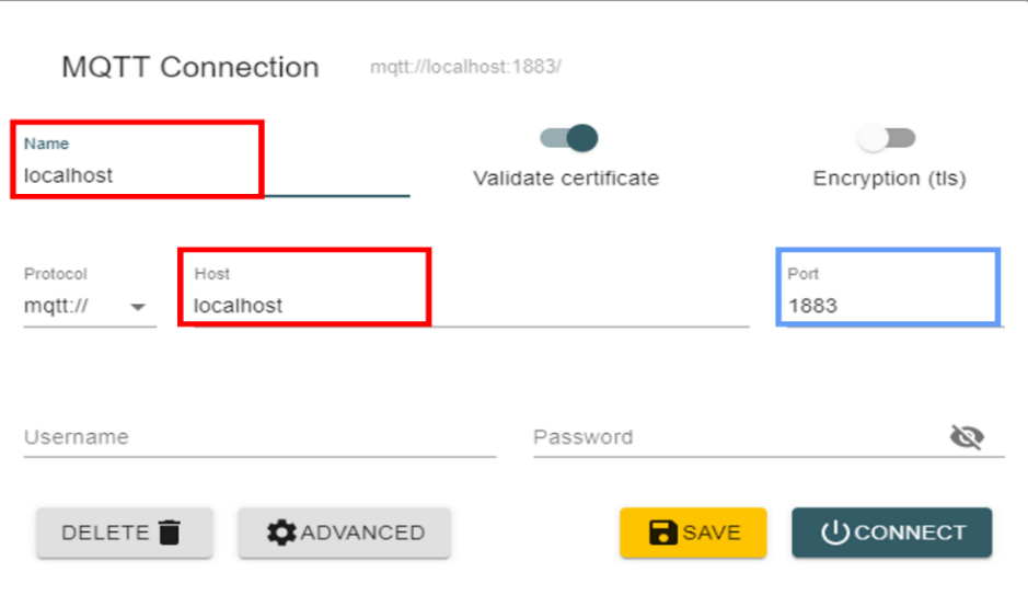
Angle reports are published to the MQTT topic silabs/aoa/angle/<locator_id>/<tag_id>.
In case the reportMode is set to IQREPORT, raw IQ reports are published to the MQTT topic silabs/aoa/iq_report/<locator_id>/<tag_id>.
The locator_id and tag_id are formed as ble-<ADDRESS_TYPE>-<BLE_ADDRESS>, where <ADDRESS_TYPE> is either sr for static random or pd for public device. <BLE_ADDRESS> is the 6-byte Bluetooth address without separators, using uppercase hexadecimal letters.
Regardless of the CTE receiving mode, the AoA host application provides a common interface for the angle data structure to the MQTT broker. A prototype of the angle data looks like:
{
"azimuth":60.0,
"azimuth_stdev":5.0,
"elevation":120.0,
"elevation_stdev":10.0,
"distance":2.5,
"distance_stdev":0,
"sequence":123
}When IQREPORT mode is enabled, the MQTT message containing the raw IQ data looks like:
{
"channel":13,
"rssi":-50,
"sequence":123,
"samples":[23, 105, 106, -10, 2, -108, ...]
}To test the AoA locator host sample application:
Flash a tag device (such as a Thunderboard BG22) with a bootloader and:
Connection-based sample app as described in Connection-Based Asset Tag Sample Application to test CONN mode.
Connectionless sample app as described in Connectionless Asset Tag Sample Application to test CONN_LESS mode.
Silabs sample app as described in Silicon Labs Enhanced (Silabs proprietary) Asset Tag Sample Application to test SILABS mode.
Flash a NCP AoA locator board with the antenna array attached to a WSTK (such as BRD4191A) with a bootloader and the NCP AoA locator firmware as described in NCP AoA Locator Sample Application. Refer to the Direction Finding Solution Guide to learn how to program BRD4191A using Simplicity Studio 6.
Make sure you have the correct build environment: Building the Single AoA Locator Host Sample Application.
Make sure you have installed Mosquitto MQTT broker: Prerequisites.
Navigate to the
/bt_aoa_host_locator/build/debugfolder.Attach the WSTK to the PC and find the port number of the virtual COM port over JLink, for example by opening a terminal program that lists serial ports:
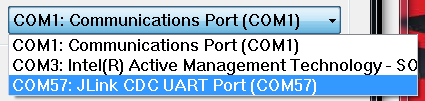
Start the host application from a command line with the COM port number. For example:
./bt_aoa_host_locator -u COM57.Alternatively, connect to your WSTK via Ethernet and start the application using its IP address. For example:
./bt_aoa_host_locator -t 192.168.1.2.If the application gets stuck at the beginning, push the reset button on the WSTK.
If the application exits at the beginning with an MQTT error, make sure that the mosquitto service is running in the background. For example, on Windows:
a. Open the Task Manager.
b. If you see the simplified view, click More details.
c. Open the Services tab.
d. Find the mosquitto service.
e. If it is stopped, right-click it, and click Start. If it is running, right-click it, and click Restart.
Open MQTT Explorer for a structured overview of the MQTT messages (angle data). Now you should see something like this:
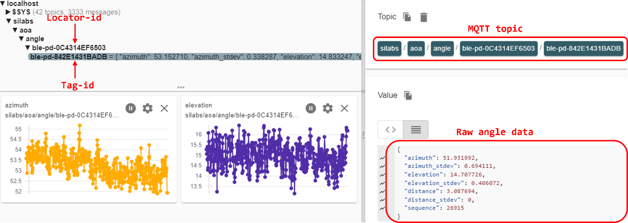
Note that steps 7 and 8 start the application using the default settings. By default, the host application starts the locator using SILABS CTE mode. If you want to test other CTE modes, you can do so on the fly through the MQTT broker using the config topic, without recompiling or restarting the application. Alternatively, you can modify the config JSON file according to your need, and start the application using the config option like this:
./bt_aoa_host_locator -u COM57 -c ../config/locator_config.json.Now, try updating the configuration of your locator by modifying any config parameters you want to see take effect. You can do so easily using the MQTT Explorer “Publish” window. For example, when testing the connection-based CTE, change the CTE mode to CONN, simply by publishing the following MQTT message using the
silabs/aoa/config/<locator_id>topic.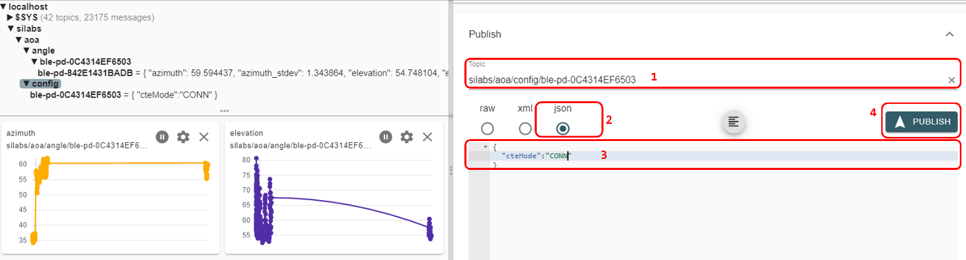
Note that the Silicon Labs proprietary approach supports scalability up to hundreds of asset tags. This approach uses the proprietary Silicon Labs CTE protocol, which improves the scalability and has low memory consumption on the AoA receiver, even with hundreds of tags. In practice this approach can support an unlimited number of tags, although a large number of tags may result in collisions on the advertising channels.
In contrast, the Connection-based and Connectionless standard solutions need more memory for the stack to keep information related to the connection status and periodic advertising syncs, respectively. Also, establishing connections or periodic advertising syncs can be time consuming, and therefore puts an absolute limit on the number of tags (about 1-50 tags on a xG22 device).
When tracking more than one tag, it is strongly recommended to disable application debug logging, as it can accumulate latencies and significantly impact the system’s real-time tracking performance.
To disable the logs, open app_log_config.h in <SDK Installation Location>|app|bluetooth|common_host|app_log|config and make the following change:
#define APP_LOG_ENABLE 0The RTL also provides IQ sample quality analysis report. The sample quality is indicated as a jitter if there is huge deviation on the antennas’ signal level between snapshots. The feature is disabled by default. To enable the feature, change the log level filter to debug level in app_log_config.h.
#define APP_LOG_LEVEL_FILTER_THRESHOLD APP_LOG_LEVEL_DEBUGIt is recommended to enable IQ sample quality analysis only for debugging purpose as it could have performance implications on the host machine.
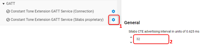
In addition, when tracking more than one tag, it is important to increase the CTE advertising interval from the default value (which is 20 ms) to at least 100 ms to prevent the locator’s UART from being congested, and more importantly avoid packet collisions. The advertising interval can be changed using the project configurator via Bluetooth > GATT > Constant Tone Extension GATT Service (Silabs proprietary) and changing the value from 32 to 160.