Sample Applications#
The sample setup consists of two types of applications, the Initiator and the Reflector. The setup uses the two-way ranging scenario. This is a connection-based measurement method where the Initiator scans for the Reflector and connects to it. After a connection is established, both the Initiator and Reflector send signals and packets to measure phase and time. The Reflector sends the measured phase and time back to the Initiator using GATT service and characteristics. The Initiator then combines all the information to calculate distance.
In general, the Simplicity SDK (SiSDK) provides sample projects for the CS Initiator and CS Reflector devices that can be run in two modes of operation—SoC Mode and NCP Mode.
The sample projects for EFR32xG24 device can be found in SSv5.
SoC Mode Sample Applications#
In SoC mode, the Bluetooth stack and the application (including the RTL library) run on the SoC/EFR32xG24 device. SiSDK 2024.12.x provides the following two Studio sample projects supporting this mode of operation.
bt_cs_soc_initiator: Bluetooth – SoC CS Reflector
bt_cs_soc_reflector: Bluetooth – SoC CS Initiator
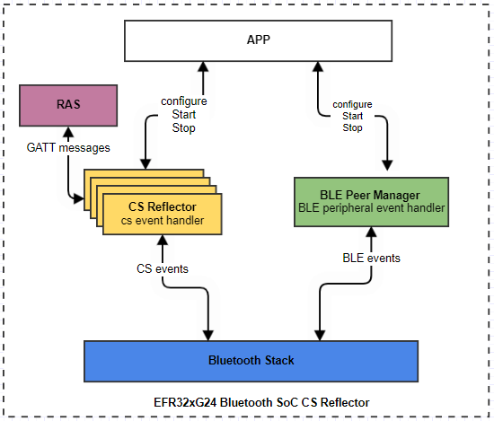
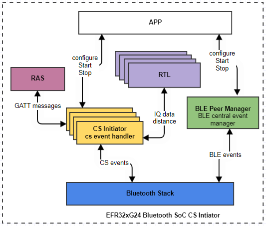
The applications consist of software components aimed at handling CS and general BLE activities and interfacing with the RTL library to yield distance estimation. The diagram below depicts a high-level software architecture of the SoC CS Initiator and Reflector sample applications.
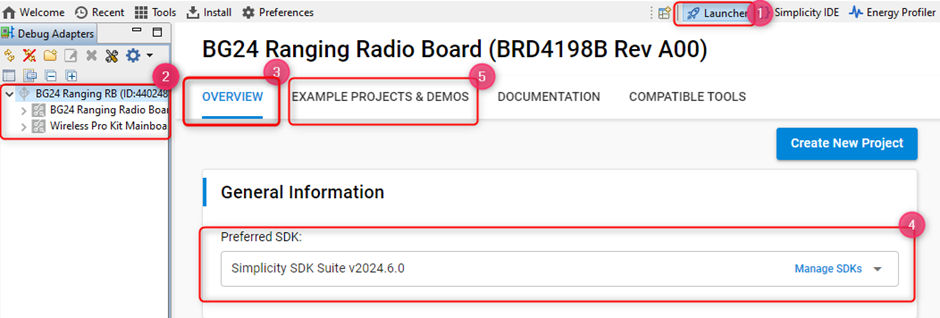
To access the projects in SSv5, in the Launcher perspective (1), select your device from the Adapter Debug window (2). In the Overview tab (3), choose the latest Simplicity SDK Suite, and then go to the EXAMPLE PROJECTS & DEMOS tab (5).
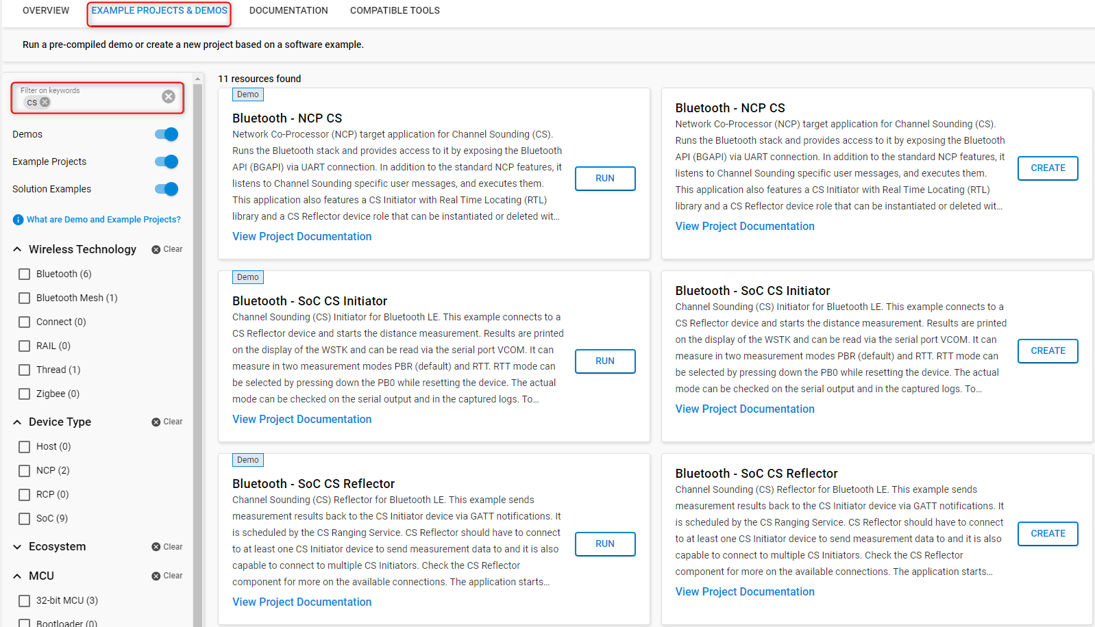
Once you are in the EXAMPLE PROJECTS & DEMOS tab, use the CS filtering keyword to see the sample applications. Click CREATE to create the project.
All the CS example projects supported on the BRD4198A and BRD2606A boards are also available as pre-built demos. For quick testing, you can run the demos by clicking RUN. This will flash the required bootloader and the corresponding sample application to your device.
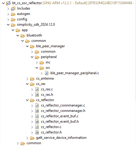
Bluetooth – SoC CS Reflector#
The main software components of the Bluetooth SoC CS Reflector are:
BLE Peer Manager
CS Reflector
CS RAS
Project Walkthrough#
The project contains the C related files under the folder <SDK_Folder>/app/bluetooth/common/.
The BLE Peer Manager is responsible for implementing the BLE peripheral roles of the Reflector device. These include configuring, starting, and stopping advertising. It accomplishes these tasks through the Bluetooth stack API calls: sl_bt_advertiser_set_timing(), sl_bt sl_bt_legacy_advertising_start(), and sl_bt_advertiser_stop(), respectively. Before advertising is started, the advertising set is created, and the advertising data is generated using sl_bt_advertiser_create_set() and sl_bt_legacy_advertiser_generate_data(), respectively. These are done in the ble_peer_manager_peripheral.c file.
The CS Reflector component is responsible for setting the maximum CS transmission power and enabling the CS Reflector role on the device for a specific connection by calling the sl_bt_cs_set_default_settings() API. This component also handles CS related events: evt_cs_security_enable_complete, which indicates that the CS Security Enable procedure has completed, evt_cs_procedure_enable_complete, which indicates the start of the CS procedure by the Initiator, and evt_cs_result, which is triggered by the local controller when a new CS result is available. These are done in the cs_reflector.c file.
The CS RAS component is responsible for parsing RAS GATT messages and creating RAS GATT responses.
Usage#
Select the Bluetooth - SoC CS Reflector sample application, and build and flash it to a device. This sample application requires the bootloader-apploader type of bootloader.
After starting up, it should be advertising with the name CS RFLCT. By default, the Reflector allows up to 4 connections. This value can be changed in the Connection software component. In multiple connection use cases, it is advised to use a longer measurement interval.
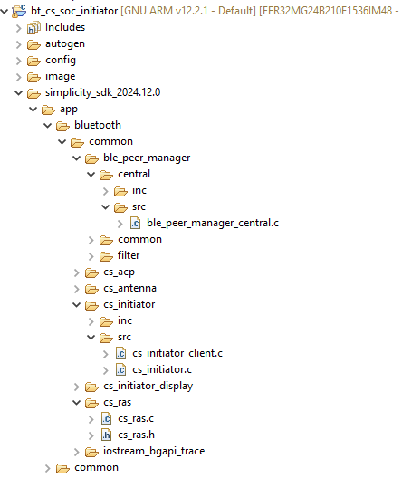
Bluetooth – SoC CS Initiator#
The main software components of the Bluetooth SoC CS Initiator are:
BLE Peer Manager
CS Initiator
RTL library
CS RAS
Project Walkthrough#
The project contains the C related files under the folder <SDK_Folder>/app/bluetooth/common/.
The BLE manager is responsible for implementing the BLE central roles of the Initiator device. This includes configuring the scanning parameters, starting/stopping the scanner, and initiating/closing a connection with a Reflector device. It achieves these by calling the Bluetooth stack APIs: sl_bt_scanner_set_parameters(), sl_bt_scanner_start()/sl_bt_scanner_stop(), sl_bt_connection_open()/sl_bt_connection_close(), respectively.
The CS Initiator component is responsible for CS related activities. These include, setting the default parameters for CS transmission power and device role using sl_bt_cs_set_default_settings(), and ensuring that the requirements for starting a CS procedure are met.
Before a CS procedure is started:
The CS capability exchange procedure should take place. This is done by calling
sl_bt_cs_read_remote_supported_capabilities(). If no capability exchange has been initiated for the connection by the host and if there is no cached copy of the capabilties of the remote device, then the controller will intiate the CS capability exchange procedure.The connection between the peer devices must be encrypted. This is done by calling
sl_bt_sm_increase_security().The CS configuration is created and configured using
sl_bt_cs_create_config()andsl_bt_cs_set_procedure_parameters ()API calls, respectively.The CS security information is exchanged by calling
sl_bt_cs_security_enable(). The Deterministic Random Bit Generator (DRBG) is seeded from security information exchanged at this step.
After these steps, the CS procedure is started using sl_bt_cs_procedure_enable() API call.
The CS Initiator is also responsible for handling CS related events triggered by the local controller and providing the CS procedure data to the RTL library, which then calculates the distance. These are done inside cs_initiator.c file.
The CS RAS component is responsible for parsing RAS GATT messages and creating RAS GATT responses.
The RTL library is responsible for doing the actual distance estimation.
Usage#
Select the Bluetooth - SoC CS Initiator application, and build and flash it to the device. This sample application requires the bootloader-apploader type of bootloader.
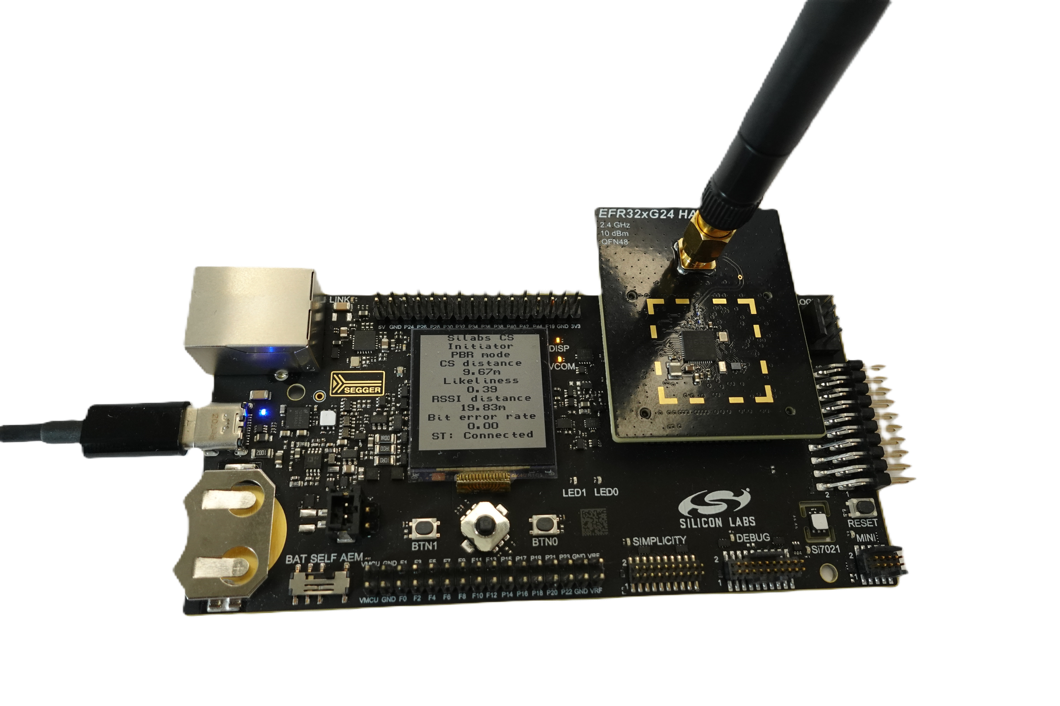
On the BRD4198A board, the initiator will display the measured distance on the LCD mounted on the main board as shown below. The LCD display will also show the Bit Error Rate (BER), the likelihood of the measured value, and RSSI based distance estimation. Note that the BER is applicable in RTT mode only.
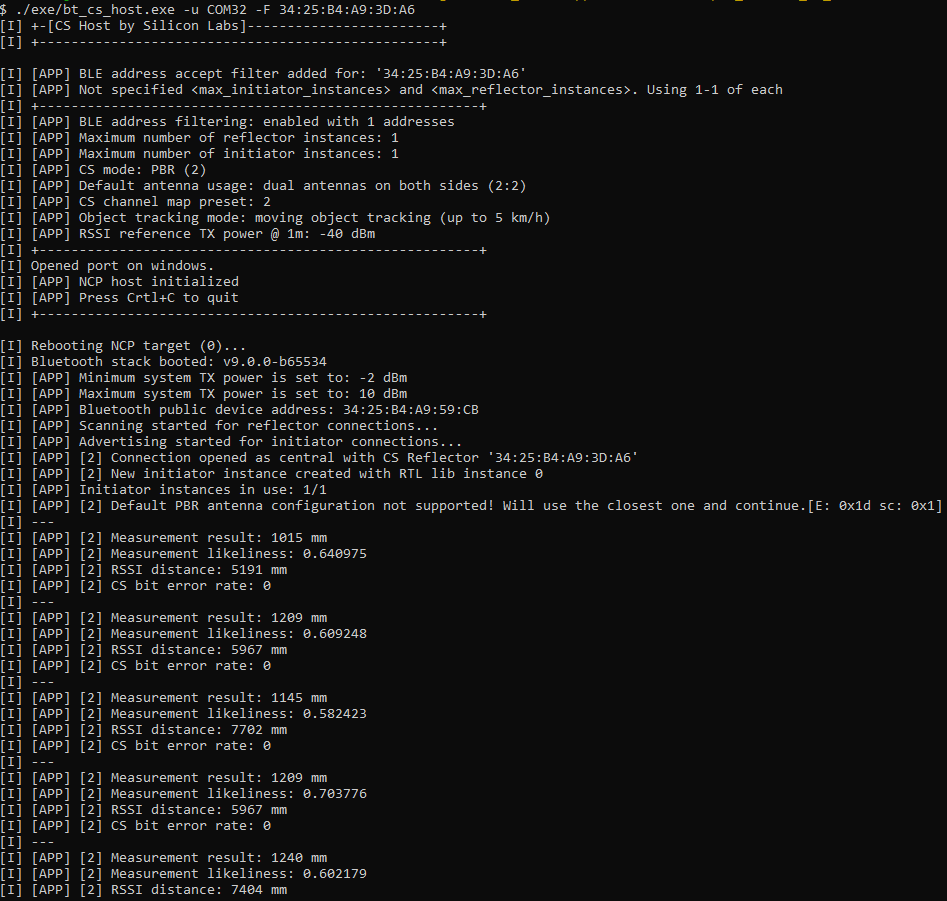
The device will also send the distances via UART. Open a console application on the PC to see the logs:
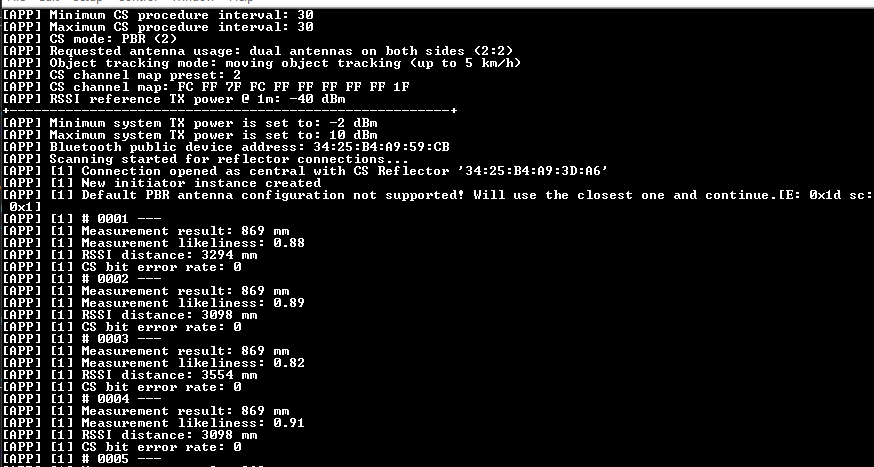
In the logs:
Measurement result: The estimated distance value using CS.Likeliness: The probability that the CS distance estimate is correct. High values (close to1) typically indicate accurate estimates, while low values (closer to 0) suggest a higher likelihood of error.RSSI distance: The RSSI based distance estimation.CS bit error rate: The number of bit errors detected (valid only in RTT mode).
Channel Sounding Sequence Chart#
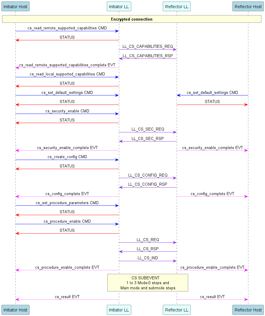
The following sequence diagram illustrates the message exchange between the Initiator and Reflector devices, based on the implementation of our sample applications. The diagram shows the BGAPI commands and events between the controller/LL and host of both devices, and the actual PHY PDUs exchanged between the Initiator and Reflector.
Configuration Options#
Several configuration options can be modified for the initiator and reflector devices to meet the requirements of different use cases.
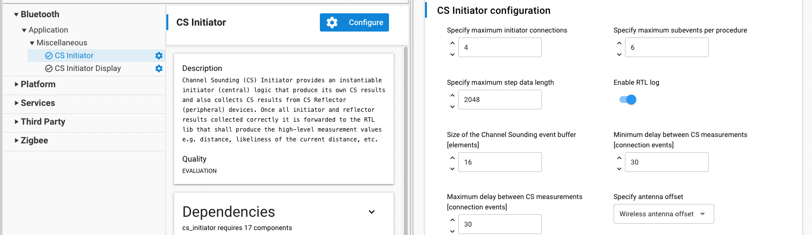
The CS initiator and procedure configurations can be modified via the CS Initiator component under Bluetooth -> Application -> Miscellaneous in the Component Editor of the NCP/SoC projects. The source file is located in
config/cs_initiator_config.h.
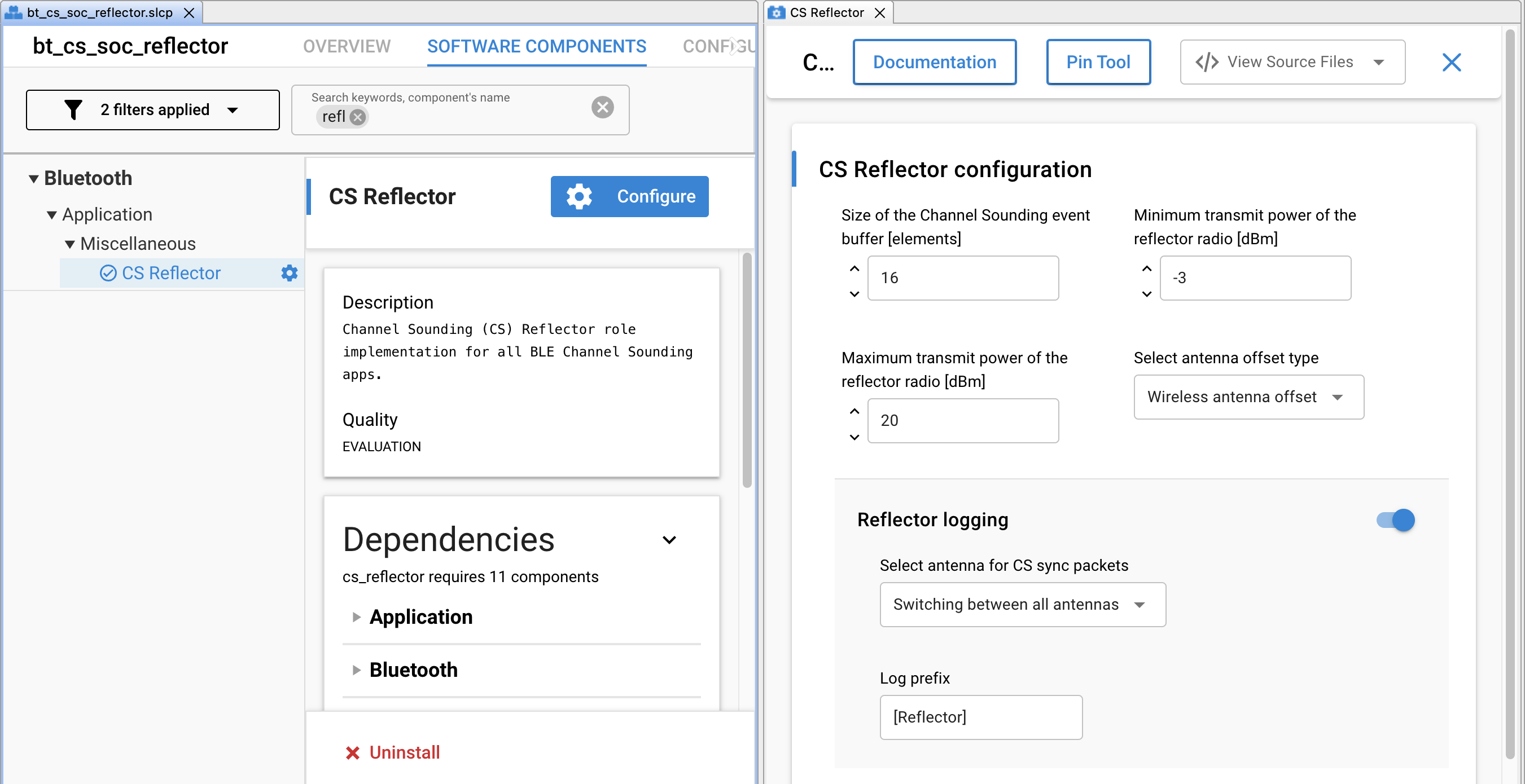
Similarly, the CS Reflector configurations can be modified via the CS Reflector component. The source file is located in
config/cs_reflector_config.h.
The most common and useful configurations are described in the following sections with references to the corresponding macro in the configuration header files.
Configuring the Antenna Offset#
For Silicon Labs development boards (Ex: BRD4198A, BRD2606A), the distance offset caused by the antenna group delay is already calibrated and configured in the initiator and reflector sample applications.
For custom boards, the default value of SL_RAIL_UTIL_CS_ANTENNA_OFFSET_WIRELESS_CM is configured to 0. The antenna offset(s) must be determined for each antenna by following the wireless distance calibration procedure as described in Section 4 of AN1493. It can then be configured in config/sl_rail_util_cs_antenna_offset_config.h or via the RAIL Utility, CS Antenna Offset component under Platform -> Radio in the Software Component Editor.
// <a.1 SL_RAIL_UTIL_CS_ANTENNA_OFFSET_WIRELESS_CM> Antenna wireless offset array in centimeters <-32768..32767>
// <d> { 0 }
#define SL_RAIL_UTIL_CS_ANTENNA_OFFSET_WIRELESS_CM { 0 }Changing the Antenna Configuration#
CS Tone#
The Antenna Configuration Index (ACI) during CS tone exchanges as described in Fundamentals is configured by the initiator. By default, the ACI is set to 7 where the initiator and reflector devices use 2 antennas each. The supported ACI values depend on the number of antennas on the device. BRD2606A supports ACI values 0, 1, 4, and 7. It can be changed inconfig/cs_initiator_config.h or in the CS initiator component as needed.
// <o CS_INITIATOR_DEFAULT_CS_TONE_ANTENNA_CONFIG_IDX_REQ> CS tone antenna configuration requested
// <i> Use all the available antennas that can be supported
// <i> Value: 0. 1 antenna path, [1:1] antenna [initiator:reflector]
// <i> Value: 1. 2 antenna path, [2:1] antenna
// <i> Value: 2. 3 antenna path, [3:1] antenna (not supported)
// <i> Value: 3. 4 antenna path, [4:1] antenna (not supported)
// <i> Value: 4. 2 antenna path, [1:2] antenna
// <i> Value: 5. 3 antenna path, [1:3] antenna (not supported)
// <i> Value: 6. 4 antenna path, [1:4] antenna (not supported)
// <i> Value: 7. 4 antenna path, [2:2] antenna
// <CS_ANTENNA_CONFIG_INDEX_SINGLE_ONLY=> 1 antenna path, [1:1] antenna
// <CS_ANTENNA_CONFIG_INDEX_DUAL_I_SINGLE_R=> 2 antenna path, [2:1] antenna
// <CS_ANTENNA_CONFIG_INDEX_SINGLE_I_DUAL_R=> 2 antenna path, [1:2] antenna
// <CS_ANTENNA_CONFIG_INDEX_DUAL_ONLY=> 4 antenna path, [2:2] antenna
// <i> Default: CS_ANTENNA_CONFIG_INDEX_DUAL_ONLY
#define CS_INITIATOR_DEFAULT_CS_TONE_ANTENNA_CONFIG_IDX_REQ CS_ANTENNA_CONFIG_INDEX_DUAL_ONLYFor custom board designs based on EFR32xG24 SoC where ACI values 2, 3, 5, and 6 can be supported and there are two antenna select GPIO pins, they should be on the same port. This allows switching both GPIOs in a single LDMA instruction, and thus enables the lowest possible antenna switching time (t_sw) value.
The GPIO(s) for antenna switching is configured in the RAIL Utility, AoX component found under Platform -> Radio in the Component Editor.
CS SYNC#
For devices with multiple antennas, the antennas can be configured for CS SYNC packet reception. By default, the CS sync antenna configuration is set to CS_SYNC_SWITCHING where the device cycles through the available antennas in a repetitive order from 0x01 to 0x04. On the initiator, it can changed in the config/cs_initiator_config.h file or in the CS Initiator component. On the reflector, it can be changed in the config/cs_reflector_config.h file or in the CS Reflector component.
Changing the CS Mode#
By default, the initiator uses the PBR mode. To switch to RTT mode, modify CS_INITIATOR_DEFAULT_CS_MODE in config/cs_initiator_config.h and set it to 1.
// <1=> RTT
// <2=> PBR
#define CS_INITIATOR_DEFAULT_CS_MODE 2Changing Connection Interval#
By default, the connection event interval is set to 7.5 ms. This setting can be changed in the config/cs_initiator_config.h. The connection interval is defined in units of 1.25ms, and ranges between 6 and 3200. The true value in ms is Value x 1.25 ms.
// <i> Default: 6
#define CS_INITIATOR_DEFAULT_MIN_CONNECTION_INTERVAL 6
// <i> Default: 6
#define CS_INITIATOR_DEFAULT_MAX_CONNECTION_INTERVAL 6Changing CS Procedure Parameter—CS Procedure Interval#
The procedure interval is defined as the number of connection events between consecutive measurement procedures.
Note that the max and min CS intervals are ignored if the maximum procedure count is set to 1. In this case, the procedure interval is limited by the time it takes to restart the procedure. Restarting a procedure consumes 9 connection intervals. CS_REQ, CS_RSP, CS_IND consumes 2, after which the devices have 7 intervals to prepare for the procedure.
By default, the interval between CS measurement procedures is set to 30 for a stable setup, even with multiple connections. If only one connection is used, this interval can be reduced to increase the refresh rate. When reducing the procedure interval, keep in mind that the interval must also accommodate enough time for the initiator to complete distance calculations. Increasing the number of antenna paths and channels used will result in more data, thereby requiring a longer procedure interval.
This setting can be changed in the config/cs_initiator_config.h.
#ifndef CS_INITIATOR_DEFAULT_MIN_PROCEDURE_INTERVAL
#define CS_INITIATOR_DEFAULT_MIN_PROCEDURE_INTERVAL (30)
#endif
#ifndef CS_INITIATOR_DEFAULT_MAX_PROCEDURE_INTERVAL
#define CS_INITIATOR_DEFAULT_MAX_PROCEDURE_INTERVAL (30)
#endifThe procedure interval is a crucial parameter, as it is used when calculating the CS sample frequency. For example, if the connection interval is 20ms and the CS procedure interval is 15, the sample interval would be 20ms * 15 = 300ms, resulting in a sample frequency of 3.3 Hz.
Changing CS Procedure Parameter—Maximum Procedure Count#
This defines the maximum number of CS procedures to be scheduled. If set to 0, the CS procedure continues in free-running mode until explicitly stopped. If set to 1, the procedure will stop after running once, after which it is restarted by the application. Keep in mind that restarting the CS procedure, consumes 9 connection intervals, and will therefore result in slower sample frequencies. Refer to our known issues for more information on current limitations regarding free running mode.
This setting can be changed in config/cs_initiator_config.h.
// <0=> Free running
// <1=> Start new procedure after one finished
// <i> Default: 1
#define CS_INITIATOR_DEFAULT_MAX_PROCEDURE_COUNT 1Changing CS Maximum TX Power#
The reference board supports a maximum TX power of 10 dBm. This value can be changed in the config/cs_initiator_config.h file.
// <i> Default: 20
#define CS_INITIATOR_DEFAULT_MAX_TX_POWER 20Enabling/Disabling Algorithm Logs#
The RTL logs can be enabled or disabled in the SoC Initiator, allowing for the capture of raw IQ samples from both the Initiator and Reflector devices for post-processing. This feature is enabled by default. To disable it, set CS_INITIATOR_RTL_LOG to 0 in the config/cs_initiator_config.h file.
#ifndef CS_INITIATOR_RTL_LOG
#define CS_INITIATOR_RTL_LOG (1)
#endifChanging Algorithm Mode#
In general, two algorithm modes are supported:
SL_RTL_CS_ALGO_MODE_REAL_TIME_BASIC: use this mode to track moving targets.SL_RTL_CS_ALGO_MODE_STATIC_HIGH_ACCURACY: use this mode to estimate the distance of stationary objects.
By default, the initiator uses the REAL_TIME mode. STATIC mode can be selected by pressing Button 1 on the WSTK at startup. Press BTN1 on the WSTK while resetting the device to select STATIC mode.
Alternatively, you can change this setting in the config/cs_initiator_config.h file.
// <SL_RTL_CS_ALGO_MODE_REAL_TIME_BASIC=> Real time basic
// <SL_RTL_CS_ALGO_MODE_STATIC_HIGH_ACCURACY=> Static high accuracy
// <i> Default: SL_RTL_CS_ALGO_MODE_REAL_TIME_BASIC
#define CS_INITIATOR_DEFAULT_ALGO_MODE SL_RTL_CS_ALGO_MODE_REAL_TIME_BASICImportant notes:
In STATIC mode, a valid distance estimation is produced for every 100 CS procedure. Hence, extra care must be taken to the returned error code by the algorithm.
SL_RTL_ERROR_ESTIMATION_IN_PROGRESS is returned by
sl_rtl_cs_processandsl_rtl_cs_get_distance_estimatemethods when distance estimation is not ready.SL_RTL_ERROR_SUCCESS is returned by
sl_rtl_cs_processandsl_rtl_cs_get_distance_estimatemethods when distance estimation is ready.
In STATIC mode, the algorithm estimates distances with a resolution of 0.1 meters.
There is currently no observable difference in the results between STATIC and REAL_TIME modes in RTT.
Changing Number of Channels#
The standard defines 79 RF channels with 1 MHz spacing in the 2.4 GHz band, with channel indices ranging from 0 to 78. The allowed range for channel sounding usage is a minimum of 15 channels and a maximum of 72 channels. Channels with indices 0, 1, 23, 24, 25, 77 and 78 are excluded due to overlap with primary advertising channels.

By default, the examples use all the allowed channels. However, this can be adjusted if using fewer channels is necessary to prioritize speed and energy efficiency over the highest possible accuracy.
The channel map can be set by selecting the desired preset value to CS_INITIATOR_DEFAULT_CHANNEL_MAP_PRESET in config/cs_initiator_config.h.
// <CS_CHANNEL_MAP_PRESET_LOW=> Low
// <CS_CHANNEL_MAP_PRESET_MEDIUM=> Medium
// <CS_CHANNEL_MAP_PRESET_HIGH=> High
// <CS_CHANNEL_MAP_PRESET_CUSTOM=> Custom
// <i> Default: CS_CHANNEL_MAP_PRESET_HIGH
#define CS_INITIATOR_DEFAULT_CHANNEL_MAP_PRESET CS_CHANNEL_MAP_PRESET_HIGHThe table below summarizes the supported channel map preset values defined in the cs_channel_map_preset_t enum type.
Preset | Channel spacing | Number of channels | Channel map |
|---|---|---|---|
| 1 | 72 | {0xFC, 0xFF, 0x7F, 0xFC, 0xFF, 0xFF, 0xFF, 0xFF, 0xFF, 0x1F} |
| 2 | 37 | {0x54, 0x55, 0x55, 0x54, 0x55, 0x55, 0x55, 0x55, 0x55, 0x15} |
| 1 | 20 | {0x00, 0x00, 0x00, 0xC0, 0xFF, 0xFF, 0x03, 0x00, 0x00, 0x00} |
| 1 | Minimum: 20 Maximum: 72 |
Each hex byte array represents a channel map, where each bit in a byte corresponds to one channel. A 1 indicates that the channel is enabled, while a 0 indicates it is disabled. The bytes are arranged in big-endian order, while the bits within each byte are in little-endian order.
In general:
A higher number of channels enhances the robustness of distance estimation by reducing large outliers.
Larger channel spacing reduces the maximum possible range that can be measured due to aliasing effect. For more details, refer to Channel Sounding Fundamentals.
If CS_CHANNEL_MAP_PRESET_CUSTOM is chosen, the application will use CS_CUSTOM_CHANNEL_MAP, which is defined in config/cs_initiator_config.h.
By default, custom preset enables all the 72 channels. You can customize it by modifying CS_CUSTOM_CHANNEL_MAP array. However, the custom channel map has certain limitations, and you must configure it with these limitations in mind:
A custom channel map can be between channel
2and channel22, and must contain minimum 20 channels with 1MHz spacing, i.e no channel can be skipped.A custom channel map can be between channel
26and channel76, and must contain minimum 20 channels with 1MHz spacing, i.e no channel can be skipped.A custom channel map can be the same as
CS_CHANNEL_MAP_PRESET_HIGH.
// <i> Default: { 0xFC, 0xFF, 0x7F, 0xFC, 0xFF, 0xFF, 0xFF, 0xFF, 0xFF, 0x1F }
#define CS_CUSTOM_CHANNEL_MAP { 0xFC, 0xFF, 0x7F, 0xFC, 0xFF, 0xFF, 0xFF, 0xFF, 0xFF, 0x1F }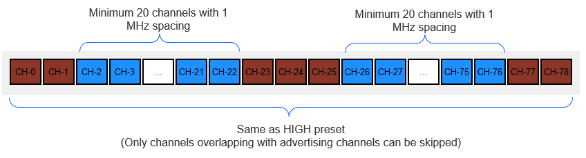
The CS Initiator component uses the sl_rtl_util_validate_bluetooth_cs_channel_map() API to validate a custom channel map. If the requirements are not met, the application closes the connection and terminates with the error code 0x24: CS_ERROR_EVENT_INITIATOR_FAILED_TO_GET_CHANNEL_MAP.
Note that, for RTT, only the CS_CHANNEL_MAP_PRESET_HIGH is currently supported.
NCP Mode Sample Applications#
The Silicon Labs Bluetooth SDK also includes NCP sample applications that support channel sounding. In NCP mode, the EFR32xG24 device functions as NCP target or coprocessor, working with a host controller that functions as an NCP host. The NCP host and target communicate on a serial interface using the BGAPI protocol.
Starting with version 2024.6.0, a multi-role NCP architecture is introduced for channel sounding. This architecture allows running multiple instances with similar or different roles simultaneously. To realize this architecture, the Bluetooth SDK offers:
A Studio example project for NCP target (app/Bluetooth/example)
bt_cs_ncp: Bluetooth - NCP for Channel Sounding
A host example for the NCP host (app/Bluetooth/example_host)
bt_cs_host: supports the multi-role NCP host
In multi-role NCP architecture, the Bluetooth stack and RTL library are run on the SoC, whereas the application is run on the host machine.
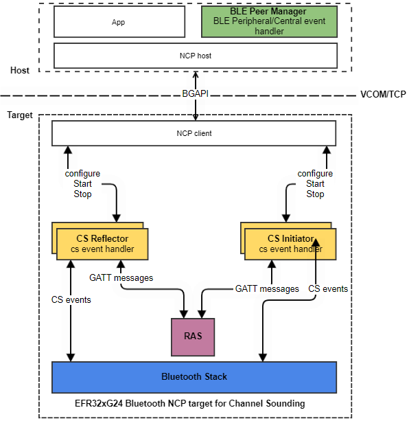
Key features of the multi-role NCP architecture:
As the name suggests, this architecture allows multiple instances* to run with different CS roles; that is, Initiator and Reflector roles.
The Initiator and Reflector roles are integrated on the NCP target side. As a result, the host application can act as a Reflector, an Initiator, or both.
The distance estimation is done on the NCP target, and only the measurement results are sent to the host using CS specific BGAPI commands, thereby reducing the load on serial communication.
*Up to 4 simultaneous connections are supported. This means that the number of instances (Initiator and Reflector combined) cannot exceed 4.
NCP Interface#
The NCP provides a high-level interface to the host application. The host can configure, start a Reflector, or Initiator instance on the NCP target by calling sl_bt_user_cs_service_message_to_target().
Any asynchronous CS event triggers an sl_bt_evt_user_cs_service_message_to_host_id event on the host. The host then parses this event to extract the specific CS event, which can be:
CS result
CS Log data from RTL, Initiator, or Reflector
Error events
This occurs in app.c file of bt_cs_host project.
Building the Multi-Role NCP Projects#
For the target, in Simplicity Studio Launcher perspective, select the Bluetooth - NCP for Channel Sounding, and build and flash it to the board. This sample application requires the bootloader-uart-bgapi type of bootloader.
For the Host application, go to app\bluetooth\example_host\bt_cs_host. For testing purposes, you can build the application by simply calling $ make.
When you are developing, however, Silicon Labs recommends that you first generate the project using the export feature of the makefile. This feature allows copying all the SiSDK files that belong to the project into the export folder. After the project files are exported, the export directory will be your working directory that is completely detached from the SiSDK but has the same folder structure inside. With export, it is clear at glance which files belong to the project.
To generate your multi-role NCP host, open a terminal, go to app\bluetooth\example_host\bt_cs_host, and call the following command:
$ make export
A custom export folder can be also specified using the EXPORT_DIR variable.
$ make export EXPORT_DIR=/c/users/username/my_bt_cs_host
After generating the project, you can build it by:
Navigating to the exported project directory
$ cd /c/users/username/my_bt_cs_host/app/bluetooth/example_host/bt_cs_hostRunning the
$ makecommand
See the required tools and more information about building an NCP Host application here.
Running the Multi-Role NCP Host Application#
After the project is built, an executable file bt_cs_host.exe is generated inside the exe folder. Run the application using the following command:
$ ./exe/bt_cs_host.exe -t <tcp_address> | -u <serial_port> [-b <baud_rate>] [-f] [-l <log_level_filter>] [-m <cs_mode>] [-R <max_reflector_instances>] [-I <max_initiator_instances>] [-F <reflector_ble_address>] [-r] [-w] [-o] [-h]
Options | Description |
|---|---|
-t | Target TCP/IP connection parameters (if WSTK is connected via Ethernet). <address> IP address of the WSTK board. |
-u | Target USB serial connection parameter (if WSTK is connected via USB). <serial_port> COM port (Windows) or device file (POSIX) to be opened. |
Optional Parameters | Description |
-b | Baudrate can be given if the connection is established via serial port. <baud_rate> Baud rate of the serial connection (default: 115200). |
-f | Disable flow control (RTS/CTS), default: enabled |
-l | Application log level filter. <level>: Integer representing log level. 0: Critical. 1: Critical, error. 2: Critical, error, warning. 3: Critical, error, warning, info (default). 4: Critical, error, warning, info, debug. |
-m | CS mode <cs_mode>: number corresponding to CS Mode. 1: RTT. 2: PBR (default). |
-I | Maximum number of initiator instances <max_initiator_instances>: 0 to 4 (default: 1). |
-R | Maximum number of reflector instances. <max_reflector_instances>: 0 to 4 (default: 1). |
-F | Enable reflector BLE address filtering. <reflector_ble_address> e.g -F 68:12:EF:34:18:AB |
-w | Use wired antenna offset. |
-o | Object tracking mode, default: 0 <o> 0: Moving object tracking (up to 5 km/h). 1: Stationary object tracking. |
-p | Pre-set parameters for channel map selection, default: 2 ( <p> 0: 1: 2: 3: |
-a | Antenna configuration index for antenna switching, default: 7 0 : Single antennas on both sides 1 : Dual antenna initiator & single antenna reflector 4 : Single antenna initiator & dual antenna reflector 7 : Dual antennas on both sides |
-q | Antenna usage for CS SYNC packets, default: 0xFE ( 1 : use antenna ID1 only 2 : use antenna ID2 only 0xFE : Switching between antennas for each channel |
-P | Use 1M connection PHY Note: Default is 2M |
-h | Displays the help menu. |
CPC Support#
The CS Initiator sample application also supports the CPC over NCP feature. For details about how to add the CPC interface to the project refer to the NCP Application Note. This covers the basic setup of the host application on a standard Linux system. It is also possible to use OpenWRT based systems as a host. Contact Silicon Labs for a sample setup and instructions.
Accessing Raw CS Step Data#
For more information on accessing and parsing raw step data from our sample applications, refer to our step data parser on Github.