Configurable Timer (CT) Architecture#
The Configurable Timer (CT) in the Silicon Labs SiWx917 device is a flexible, high-performance timing engine built within the Arm® Cortex-M4 subsystem. It provides deterministic timing, precise control, and broad configurability for applications requiring reliable timing, waveform generation, or event measurement.
You can configure each CT counter independently or synchronize multiple counters to achieve coordinated timing behavior across your system.
Peripheral Overview#
The CT peripheral enables precise time control and versatile signal operations in the SiWx917. Each timer can operate individually or in synchronization with another counter for coordinated waveform generation or event capture.
Key Features#
Two independent 16-bit counters (Counter0 and Counter1)
Programmable clock and event sources for timer ticks
Counter modes: Up, Down, and Up-Down
One input and two output signals per counter
Pulse-width modulation (PWM) with flexible duty cycles and waveforms
Output modulation and programmable toggling on input triggers
Event capture for measuring signal transitions
Direct memory access (DMA) integration for low-latency, jitter-free data handling
Interrupt generation for compare, capture, and overflow events
These features allow you to design real-time control systems, generate high-speed PWM signals, and measure external input events with precision.
Software Architecture#
The SiWx917 Configurable Timer software stack uses a layered architecture to ensure modularity, scalability, and ease of integration. This approach simplifies application development and provides consistent APIs across timer peripherals.
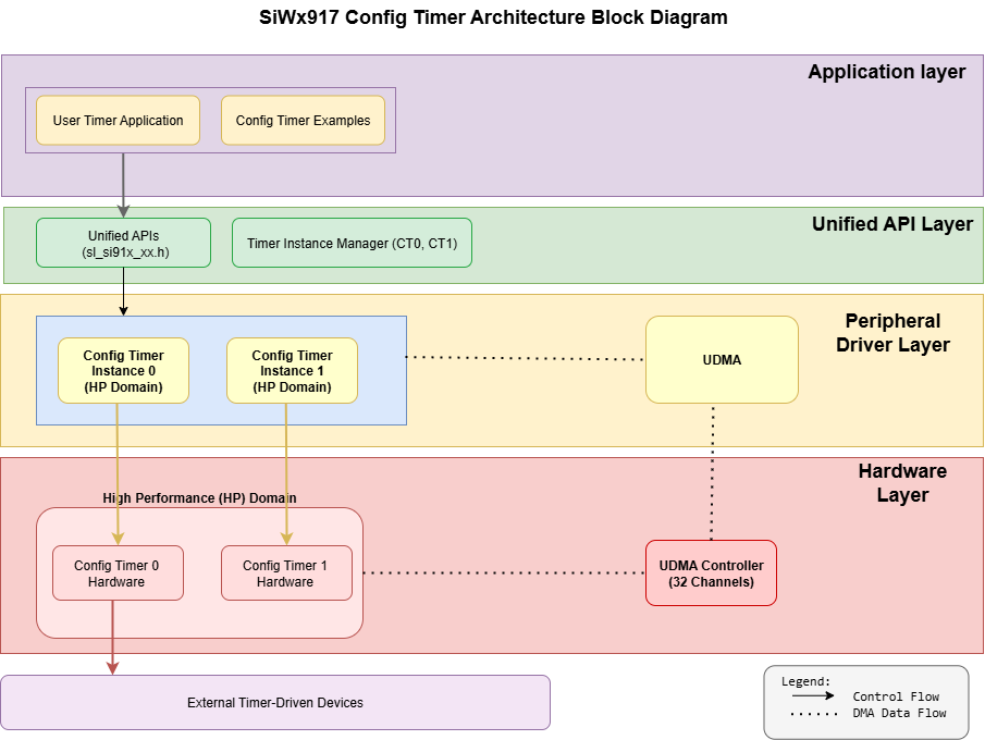
Layer Overview#
Layer | Description |
|---|---|
Application Layer | Implements timer-driven application logic, such as PWM control, event counting, or waveform generation using the CT driver APIs. |
Unified API Layer | Provides high-level driver APIs for initialization, configuration, control, and event handling. It abstracts hardware details and ensures consistent integration with other SiWx917 drivers. |
Peripheral Driver Layer | Handles register access, interrupt servicing, and DMA operations. This layer manages low-level control of CT hardware resources. |
Hardware Layer | Represents the CT block within the SiWx917 SoC, including counters, compare units, input/output channels, and connections to the system clock tree. |
This modular design ensures reliable operation, easy debugging, and maintainable code when scaling your timing solution.
Directory Structure in WiSeConnect Software Development Kit (SDK)#
In the WiSeConnect SDK, CT driver components are organized under the unified driver framework.
The following structure shows where CT-related files are located.
wiseconnect/
├── components/
│ └── device/
│ └── silabs/
│ └── si91x/
│ └── mcu/
│ └── drivers/
│ ├── unified_api/ // Main CT component
│ │ ├── inc/
│ │ │ └── sl_si91x_config_timer.h // Public API header
│ │ ├── src/
│ │ │ └── sl_si91x_config_timer.c // Implementation
│ │ ├── config/
│ │ │ └── sl_si91x_config_timer_config.h // UC configuration
│ │ └── component/
│ │ └── sl_config_timer.slcc // Component configuration
│ └── peripheral_drivers/ // Low-level CT library
│ ├── inc/
│ │ └── rsi_ct.h // Hardware abstraction
│ ├── src/
│ │ └── rsi_ct.c // Low-level implementation
│ └── component/
│ └── rsilib_ct.slcc // Low-level component
├── examples/
│ └── si91x_soc/
│ └── peripheral/
│ ├── config_timer/ // Basic CT examples
│ └── config_timer_dma/ // CT with DMA examples
├── resources/
├── defaults/
└── sl_config_timer.h // Default configurationNote: The SDK path uses “si91x” for folder naming consistency across related product families, but the driver implementation and APIs apply directly to SiWx917 devices.
Clock and Power Management#
The Configurable Timer (CT) is part of the High-Performance (HP) domain in the SiWx917 device. It delivers precise, deterministic timing when the HP domain is active and automatically suspends during transitions to low-power states.
This approach ensures optimal energy efficiency without compromising timing reliability.
When the HP domain is active, the CT operates with full functionality and deterministic timing.
When the system enters low-power mode, the CT (core timer) power domain is gated off, and the CT becomes non-operational while the core is in sleep. After the core wakes up, the CT must be reinitialized to resume its functionality.
Note: You do not need to configure clock or power registers manually. The WiSeConnect SDK and Simplicity Studio automatically manage CT clock and power control when you add or configure CT components in your project.
Power Domain Overview#
The SiWx917 device includes two Configurable Timer instances, both located in the MCU HP domain. This placement allows access to high-frequency clocks for precise, low-jitter timing applications.
CT Instance | Base Address | Domain | Description |
|---|---|---|---|
CT0 |
| MCU HP Domain | High-precision timing and PWM generation |
CT1 |
| MCU HP Domain | Parallel or synchronized timing operations |
Dependencies#
Before using the Configurable Timer, make sure the following dependencies are met:
WiSeConnect SDK installed and configured in Simplicity Studio.
Project
.slcpconfiguration file includes the CT components.Universal Configurator (UC) used to set timer mode, direction, and trigger sources.
Power-state management handled automatically through the HP domain.
GPIO configuration for CT input/output pins using the UC pin tool or driver APIs.
DMA buffers used for updating Output Compare values, are located in standard RAM to ensure optimal performance.
For complete setup and configuration guidance (including component selection, UC setup, and code generation), refer to the Configurable Timer Initialization and Configuration Guide.