Analog Peripherals Architecture#
The SiWx917 system-on-chip (SoC) integrates a flexible set of analog peripherals, including the analog-to-digital converter (ADC) and digital-to-analog converter (DAC), in both high-performance (HP) and ultra-low-power (ULP) variants. These peripherals support precise sensing, waveform generation, low-power monitoring, and high-throughput data acquisition for a wide range of embedded applications.
This section provides an architectural overview of the ADC and DAC subsystems, including operating modes, data paths, power-domain behavior, and integration with the WiSeConnect software development kit (SDK).
Peripheral Overview#
SiWx917 provides two analog peripheral classes.
High-performance (HP) ADC and DAC#
Optimized for high sampling rates and performance-critical applications.
Operate in PS4 (active) and PS3 (active) power states.
Support direct memory access (DMA) for high-throughput operation.
Suitable for waveform generation and rapid sampling.
Ultra-low-power (ULP) ADC and DAC#
Designed for low-frequency, energy-efficient monitoring.
Remain active in deeper power states, including PS2.
Provide lower maximum sampling rates with significantly reduced current consumption.
Suitable for battery-powered, always-on sensing applications.
System Dependencies#
To use analog peripherals effectively, ensure the following dependencies are in place:
WiSeConnect SDK installed and configured in Simplicity Studio.
Simplicity Studio project configuration (
.slcp) that includes ADC and DAC components.Universal Configurator (UC) used to configure sampling rates, modes, and thresholds.
Clock management provided by the microcontroller unit (MCU) clock architecture.
Power management determined by the active power state (PS2 through PS4).
General-purpose input/output (GPIO) pins configured for analog operation.
DMA buffers allocated in ULP memory for optimal power efficiency.
Reference voltage (VREF) defined for accurate conversions.
For installation, setup, and configuration, see the Analog Peripherals Initialization and Configuration Guide.
Key Features#
ADC Features#
The auxiliary analog-to-digital converter (AUXADC) supports single-ended and differential inputs and produces 12-bit digital output with optional noise averaging.
Its VREF can connect directly from the battery-backed supply (VBAT) in low-dropout (LDO) bypass mode or from the auxiliary LDO output.
Supported operating modes:
Single-ended input with noise averaging
Single-ended input without noise averaging
Differential input with noise averaging
Differential input without noise averaging
Shutdown mode
DAC Features#
The auxiliary digital-to-analog converter (AUXDAC) converts 10-bit digital input values into analog voltages ranging from (5 × VDD / 36) to (31 × VDD / 36). The supply voltage (VDD) ranges from 1.8 V to 3.6 V.
Key characteristics include:
Dual output pins through multiplexing.
Operational and shutdown modes.
Monotonic voltage output.
FIFO and static operation supported.
ADC Architecture#
The ADC controller provides 12-bit resolution and supports high-speed sampling for performance-critical applications.
Sampling capabilities:
Up to 2.5 MSPS
Functional highlights include:
Up to 16 channels with DMA support.
Static (single) and FIFO (continuous) modes.
Single-ended or differential inputs.
Dual buffering (ping/pong) for loss-free sampling.
Optional noise averaging for precision applications.
ADC Directory Structure (WiSeConnect SDK)#
wiseconnect/
├── components/
│ └── device/silabs/si91x/mcu/drivers/
│ ├── peripheral_drivers/
│ │ ├── inc/rsi_adc.h
│ │ └── src/rsi_adc.c
│ ├── unified_api/
│ │ ├── inc/sl_si91x_adc.h
│ │ └── src/sl_si91x_adc.c
├── examples/
│ └── si91x_soc/peripheral/
│ ├── sl_si91x_adc_fifo_mode
│ ├── sl_si91x_adc_static_mode
│ └── sl_si91x_ulp_adcDAC Architecture#
The DAC controller provides 10-bit resolution and supports sampling rates up to 5 MHz.
Core capabilities include:
Static (DC output) and FIFO (waveform generation) modes.
Sampling rates from 63 samples per second (SPS) to 5 mega samples per second (MSPS).
Configurable FIFO thresholds for interrupt generation.
Monotonic design to ensure smooth analog output.
DAC Directory Structure (WiSeConnect SDK)#
wiseconnect/
├── components/
│ └── device/silabs/si91x/mcu/drivers/
│ ├── peripheral_drivers/
│ │ ├── inc/rsi_dac.h
│ │ └── src/rsi_dac.c
│ ├── unified_api/
│ │ ├── inc/sl_si91x_dac.h
│ │ └── src/sl_si91x_dac.c
├── examples/
│ └── si91x_soc/peripheral/
│ ├── sl_si91x_dac
│ └── sl_si91x_ulp_dacAnalog Peripherals Software Architecture#
The analog peripherals software stack uses a layered design to provide hardware abstraction, modularity, and power efficiency.
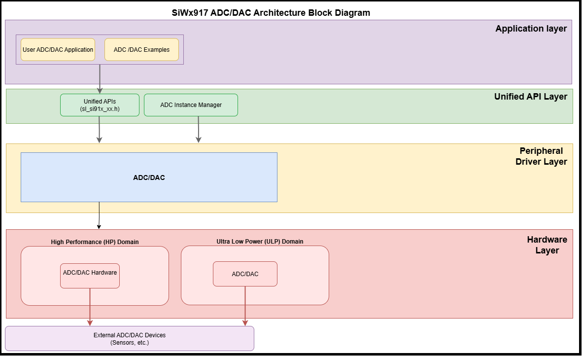
Software Layers#
Application layer: User applications and SDK examples.
Unified API layer: High-level APIs for initialization and data handling.
Peripheral driver layer: Low-level hardware access.
Hardware layer: Physical ADC and DAC peripherals in the SiWx917 SoC.
This structure supports code reuse and high-throughput sampling through DMA.
Clock and Power Management#
The SDK manages clock and power domains for analog peripherals automatically.
High-performance state (PS4 and PS3): In this mode, the ADC operates with a 40 MHz crystal oscillator as the source clock, enabling maximum sampling frequency performance.
Ultra-low-power state (PS2): In this mode, the ADC can operate using a 32 MHz internal RC clock, making it well-suited for low-power applications.
You typically do not need manual clock register configuration. For advanced tuning, see the hardware reference manual or the Analog Peripherals Low Power Instance Guide.
Power Domain Overview#
Domain | Peripherals | Power States | Description |
|---|---|---|---|
High-Performance (HP) | ADC, DAC | PS4, PS3 | Optimized for high-speed sampling. |
Ultra-Low-Power (ULP) | ULP_ADC, ULP_DAC | PS4, PS3, PS2 | Designed for low-power continuous monitoring. |
Base address:
HP AUX ADC/DAC Controller —
0x2404_3800
Dependencies#
Analog peripherals rely on coordinated hardware and software components:
Hardware interfaces: ADC and DAC registers, analog I/O, and VREF inputs.
System components: Clock and power management, DMA, and interrupts.
SDK components: WiSeConnect SDK, driver libraries, and CMSIS headers.
Development tools: Simplicity Studio, Universal Configurator, and pin configuration tools.