Implement the Hardware Abstraction Layer#
This section explains how to define the HAL API functions using host MCU platform-specific drivers.
GPIO Handling#
For the SDK v3.x’s HAL to communicate to SiWx917™ NCP through the host MCU platform, certain GPIOs on the host MCU platform should be configured. The following tables explain the GPIOs on SiWx917 NCP that need to be configured by the host MCU.
Note: The BRD8045A Board Pins indicate the EXP Interface (J100) Pin numbers. The BRD8045C Pins indicate the SPI Shield Interface( P101, P102, P103, and P104) Pin numbers. Check the Schematics of BRD8045A and BRD8045C for more details.
Common GPIOs#
Signal name | Pin name on chip as per SiWx917 NCP datasheet | BRD8045A EXP Adapter Board Pin | BRD8045C Shield Adapter Board Pin | I/O direction to host MCU | Description |
|---|---|---|---|---|---|
Reset | RESET_N | J100.11 | P101.2 | Output | The host MCU must use this GPIO to reset the SiWx917 NCP. |
Low Power GPIOs#
Signal name | Pin name of chip as per SiWx917 NCP datasheet | BRD8045A EXP Adapter Board Pin | BRD8045C Shield Adapter Board Pin | I/O direction to host MCU | Description |
|---|---|---|---|---|---|
Sleep/Wake indications from SiWx917 NCP | UULP_VBAT_GPIO_0 / SLEEP_IND_FROM_DEV | J100.7 | P103.5 | Input | The host MCU must use this GPIO to get sleep/wake indications from SiWx917 NCP. |
Sleep/Wake requests from host MCU | UULP_VBAT_GPIO_2 / HOST_BYP_ULP_WAKEUP | J100.9 | P103.3 | Output | The host MCU must use this GPIO to make sleep/wake requests to SiWx917 NCP . |
Communication Interface GPIOs#
Currently, the SDK v3.x supports SPI and UART interfaces. Let us go through the interface signals connected between the host MCU and the SiWx917 NCP.
SPI Interface#
For SPI interface, the host MCU should be configured as SPI master and SiWx917 should be configured as SPI Slave. For SPI interface, an additional signal – GPIO interrupt signal needs to be configured at the host MCU.
Signal name | Pin name of chip as per SiWx917 NCP datasheet | BRD8045A EXP Adapter Board Pin | BRD8045C Shield Adapter Board Pin | I/O direction to host MCU | Description |
|---|---|---|---|---|---|
SPI Clock | GPIO_25/SPI_CLK | J100.8 | P101.6 | Output | The host MCU must use this GPIO to source SPI Clock for data synchronization |
SPI MISO | GPIO_28/SPI_MISO | J100.6 | P101.5 | Input | The host MCU must use this GPIO to receive data/command responses from SiWx917 NCP |
SPI MOSI | GPIO_27/SPI_MOSI | J100.4 | P101.4 | Output | The host MCU must use this GPIO to send data/commands to SiWx917 NCP |
SPI CS | GPIO_26/SPI_CSN | J100.10 | P101.3 | Output | The host MCU must use this GPIO to select the SiWx917 chip as its slave whenever it wants to communicate to SiWx917 NCP |
GPIO Interrupt | GPIO_29/SPI_INTR | J100.13 | P101.1 | Input | The host MCU must use this GPIO to get frame pending interrupts from SiWx917 NCP |
GPIO Interrupt Handling for SPI Interface#
The SiWx917 NCP shall raise frame pending interrupt to the host MCU indicating that it is about to send a frame. Upon reception of frame, the SDK v3.x’s NCP_HOST_BUS_RX_EVENT event should be set, for the SDK v3.x to process the incoming frame. This requires a GPIO Interrupt to be configured at the host end. The GPIO Interrupt should contain a logic that would set NCP_HOST_BUS_RX_EVENT event.
For example:
For STM32, the GPIO Interrupt Pin selected is PA9. The Interrupt Request (EXTI9_5_IRQn) related to PA9 GPIO is enabled. As per STM32F411RE, the Interrupt Request (EXTI9_5_IRQn) is mapped to EXTI9_5_IRQHandler(). The EXTI9_5_IRQHandler() should contain a logic to set the NCP_HOST_BUS_RX_EVENT event and clear the interrupt as well. This can be done by setting NCP_HOST_BUS_RX_EVENT (BIT(2)) using osEventFlagsSet() function or by calling the utility function sl_si91x_bus_rx_irq_handler() (prototype is present at components/device/silabs/si91x/wireless/inc/sl_rsi_utility.h).
For EFR32xG24, the GPIO Interrupt Pin selected is PA7. For the Interrupts that arrive on Odd Pin numbers (here PA7 is an Odd pin number), the interrupt/callback handler that shall be invoked is GPIO_ODD_IRQHandler(). The GPIO_ODD_IRQHandler() should contain a logic to set the NCP_HOST_BUS_RX_EVENT event and clear the interrupt as well.
UART Interface#
For UART interface, no additional GPIO interrupt signal is needed.
Signal name | Pin name of chip as per SiWx917 NCP datasheet | BRD8045A EXP Adapter Board Pin | BRD8045C Shield Adapter Board | Pin I/O direction to host MCU | Description |
|---|---|---|---|---|---|
UART RX | GPIO_8/UART1_RX | J100.14 | P103.1 | Output | The host MCU must use this GPIO to receive data/command responses from SiWx917 NCP |
UART TX | GPIO_9/UART1_TX | J100.12 | P103.2 | Input | The host MCU must use this GPIO to send data/commands to SiWx917 NCP |
UART CTS | GPIO_15/UART1_CTS | Not yet routed | Not yet routed | Input | The host MCU must use this GPIO to receive CTS signal |
UART RTS | GPIO_12/UART1_RTS | Not yet routed | Not yet routed | Output | The host MCU must use this GPIO to send RTS signal |
Mapping to the Host#
Choose the host MCU GPIOs and map them to SiWx917 NCP as mentioned above.
For EFR32xG24, the mapping is as follows with a SPI interface:
Signal name | Pin name of chip as per SiWx917 NCP datasheet | EFR32xG24 Pin number |
|---|---|---|
SPI Clock | GPIO_25/SPI_CLK | PC3 |
SPI MISO | GPIO_28/SPI_MISO | PC2 |
SPI MOSI | GPIO_27/SPI_MOSI | PC1 |
SPI CS | GPIO_26/SPI_CSN | PC0 |
GPIO Interrupt | GPIO_29/SPI_INTR | PA7 |
Sleep/Wake indications from SiWx917 NCP | UULP_VBAT_GPIO_0 / SLEEP_IND_FROM_DEV | PA5 |
Sleep/Wake requests from host MCU | UULP_VBAT_GPIO_2 / HOST_BYP_ULP_WAKEUP | PD2 |
Reset | RESET_N | PA6 |
For STM32, the mapping is as follows with a SPI interface:
Signal name | Pin name of chip as per SiWx917 NCP datasheet | STM32 Pin number |
|---|---|---|
SPI Clock | GPIO_25/SPI_CLK | PA5 |
SPI MISO | GPIO_28/SPI_MISO | PA6 |
SPI MOSI | GPIO_27/SPI_MOSI | PA7 |
SPI CS | GPIO_26/SPI_CSN | PB6 |
GPIO Interrupt | GPIO_29/SPI_INTR | PA9 |
Sleep/Wake indications from SiWx917 NCP | UULP_VBAT_GPIO_0 / SLEEP_IND_FROM_DEV | PB5 |
Sleep/Wake requests from host MCU | UULP_VBAT_GPIO_2 / HOST_BYP_ULP_WAKEUP | PA10 |
Reset | RESET_N | PC7 |
Create HAL Files#
Two HAL files should be created. One is a c header file to keep track of definitions of GPIOs and the other is a c source file to define HAL functions.
It is important to keep track of definitions for GPIO Ports and Pins used for interfacing SiWx917 with host MCU for better readability and maintenance. The GPIO definitions should be provided in a file name
sl_board_configuration.hand this file should be included in your application project. For this, create a header file with namesl_board_configuration.hand include it in your project.For
sl_board_configuration.hin case of EFR32xG24, refer here.For
sl_board_configuration.hin case of STM32, create a new folder with namestm32f411rewithin the Sample STM32 Project atcomponents/device/silabs/si91x/wireless/host_mcuand add all the GPIO definitions.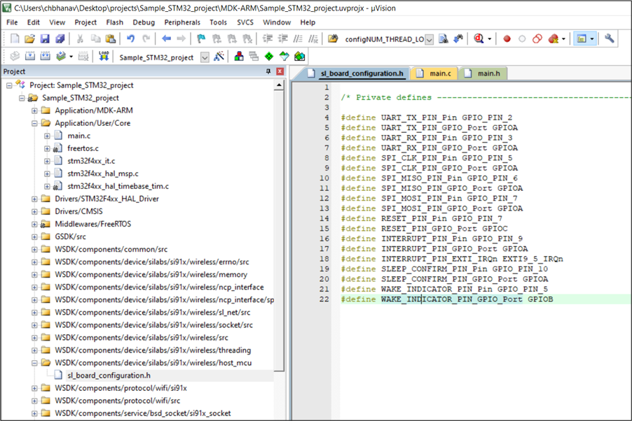
The C source file should be created to define the HAL API functions. The HAL API functions prototypes are present in the file
sl_si91x_host_interface.hlocated atWSDK/components/device/silabs/si91x/wireless/inc. The function definitions for EFR32xG24 and STM32 shall be explained in the following sections.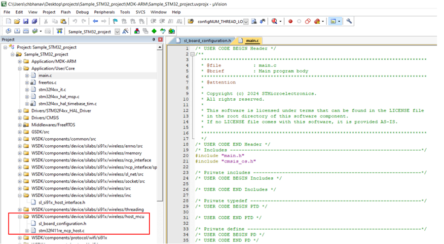
The following HAL API functions are explained in the following sections. There are listed here in alphabetical order:
sl_si91x_host_clear_sleep_indicator | sl_si91x_host_deinit | sl_si91x_host_disable_bus_interrupt | sl_si91x_host_enable_bus_interrupt | sl_si91x_host_enable_high_speed_bus | sl_si91x_host_get_wake_indicator | sl_si91x_host_hold_in_reset | sl_si91x_host_init | sl_si91x_host_release_from_reset | sl_si91x_host_set_sleep_indicator | sl_si91x_host_spi_transfer | sl_si91x_host_uart_transfer
Host Initialization Functions#
The following functions are covered in this section. These are mentioned in the sequence in which they occur in the flow of an application:
sl_si91x_host_init | sl_si91x_host_deinit
sl_si91x_host_init#
Prototype#
sl_status_t sl_si91x_host_init(sl_si91x_host_init_configuration *config);
Description#
In this function, the host must configure the interface-related, low power, common GPIOs and Interrupts that are required to communicate with SiWx917 NCP.
Parameters#
The sl_si91x_host_init_configuration structure is defined as below:
typedef sl_status_t (*sl_si91x_host_rx_irq_handler)(void);
typedef void (*sl_si91x_host_rx_done_handler)(void);
typedef struct {
sl_si91x_host_rx_irq_handler rx_irq;
sl_si91x_host_rx_done_handler rx_done;
} sl_si91x_host_init_configuration;The structure can be passed as NULL or can be used as a utility to set SDK v3.x’s Bus RX event upon receiving an Incoming frame pending Interrupt from the SiWx917 NCP for SPI Interface. For details, see the GPIO Interrupt Handling for SPI Interface section.
Return values#
SL_STATUS_OK - if the host initialization is successful.
SL_STATUS_FAIL - if the host initialization fails.
Note: These status codes are from sl_status.h file of GSDK.
Examples#
EFR32: Refer here for the definition of function.
STM32:
sl_status_t sl_si91x_host_init(sl_si91x_host_init_configuration *config)
{
UNUSED_PARAMETER(config);
uint32_t status = 0;
//! Initialize the host platform GPIOs
MX_GPIO_Init();
//! Initialize DMA
MX_DMA_Init();
//! Initialize SPI
MX_SPI1_Init();
if (init_error != 0) {
return SL_STATUS_FAIL;
}
return SL_STATUS_OK;
}sl_si91x_host_deinit#
Prototype#
sl_status_t sl_si91x_host_deinit(void);
Description#
In this function, the host must de-initialize the things related to SiWx917 if any, such as memory allocation.
Parameters#
None
Return values#
SL_STATUS_OK - if the host deinitialization is successful.
SL_STATUS_FAIL - if the host deinitialization fails.
Examples#
EFR32: Refer here for the definition of function.
STM32:
sl_status_t sl_si91x_host_deinit(void)
{
return SL_STATUS_OK;
}Host Interface Functions#
The following functions are covered in this section for various types of interfaces between the application and the SiWx91x network processor for the Serial Peripheral Interface (SPI), and Universal Asynchronous Receiver-Transmitter (UART) interface respectively:
sl_si91x_host_spi_transfer | sl_si91x_host_enable_high_speed_bus | sl_si91x_host_uart_transfer
sl_si91x_host_spi_transfer#
Prototype#
sl_status_t sl_si91x_host_spi_transfer(const void *tx_buffer, void *rx_buffer, uint16_t buffer_length);
Description#
In this function, the host must write an implementation to transfer/receive data to/from the SiWx917 through the SPI interface.
Parameters#
tx_buffer - a void pointer that points to the address of data buffer to be transmitted to the SiWx91x NCP
rx_buffer - a void pointer that points to the address of data buffer to be received from the SiWx91x NCP
buffer_length - Length of data to be transmitted/received
Note: In the SDK v3.x, for certain sl_si91x_host_spi_transfer() API calls, the tx_buffer and rx_buffer are passed as NULL.
Return values#
SL_STATUS_OK - if successful.
SL_STATUS_FAIL - if fails.
Examples#
EFR32: Refer here for the definition of function.
STM32:
#define SPI_BUFFER_LENGTH 1600
uint8_t spi_buffer[SPI_BUFFER_LENGTH];
sl_status_t sl_si91x_host_spi_transfer(const void *tx_buffer, void *rx_buffer, uint16_t buffer_length)
{
if (rx_buffer == NULL) {
rx_buffer = spi_buffer;
}
if (tx_buffer == NULL) {
tx_buffer = spi_buffer;
}
#ifdef DMA_ENABLED
HAL_SPI_TransmitReceive_DMA(&hspi1, (uint8_t *)tx_buffer, (uint8_t *)rx_buffer, buffer_length);
while (!dma_tx_rx_completed) {
}
dma_tx_rx_completed = 0;
#else
HAL_SPI_TransmitReceive(&hspi1, (uint8_t *)tx_buffer, (uint8_t *)rx_buffer, buffer_length, 10);
#endif
return SL_STATUS_OK;
}sl_si91x_host_enable_high_speed_bus#
Prototype#
void sl_si91x_host_enable_high_speed_bus();
Description#
In case of using SPI with high clock frequency> 25 MHz, the host must initialize the interface with a clock frequency less than 25 MHz. In this function, a logic should be implemented to switch the host’s SPI Clock frequency to > 25 MHz. This function can be left empty if SPI Clock frequency > 25 MHz is not required.
Parameters#
None
sl_si91x_host_uart_transfer#
Prototype#
sl_status_t sl_si91x_host_uart_transfer(const void *tx_buffer, void *rx_buffer, uint16_t buffer_length);
Description#
In this function, the host must write an implementation to transfer/receive data to/from the SiWx917 through the UART interface.
Parameters#
tx_buffer - a void pointer that points to the address of data buffer to be transmitted to the SiWx91x NCP
rx_buffer - a void pointer that points to the address of data buffer to be received from the SiWx91x NCP
buffer_length - Length of data to be transmitted/received
Return values#
SL_STATUS_OK - if successful.
SL_STATUS_FAIL - if fails.
Examples#
EFR32: Refer here for the definition of function.
STM32: To be implemented.
Return values#
None
GPIO Functions#
The following functions are covered in this section for reset, sleep indicator, and wake indicator GPIOs respectively:
sl_si91x_host_hold_in_reset | sl_si91x_host_release_from_reset | sl_si91x_host_set_sleep_indicator | sl_si91x_host_clear_sleep_indicator | sl_si91x_host_get_wake_indicator
sl_si91x_host_hold_in_reset#
Prototype#
void sl_si91x_host_hold_in_reset(void);
Description#
This function should contain the host platform specific GPIO function call to drive the RESET_N GPIO from high to low (resets the SiWx917 NCP).
Parameters#
None.
Return values#
None
Examples#
EFR32:
void sl_si91x_host_hold_in_reset(void)
{
GPIO_PinModeSet(RESET_PIN.port, RESET_PIN.pin, gpio-ModePushPull, 1);
GPIO_PinOutClear(RESET_PIN.port, RESET_PIN.pin);
} STM32:
void sl_si91x_host_hold_in_reset(void)
{
HAL_GPIO_WritePin(RESET_PIN_GPIO_Port, RESET_PIN_Pin, GPIO_PIN_RESET);
}sl_si91x_host_release_from_reset#
Prototype#
void sl_si91x_host_release_from_reset(void);
Description#
This function should contain the host platform specific GPIO function call to drive the RESET_N GPIO high (releases SiWx917 from reset).
Parameters#
None
Return values#
None
Examples#
EFR32:
void sl_si91x_host_release_from_reset(void)
{
GPIO_PinModeSet(RESET_PIN.port, RESET_PIN.pin, gpioMode-WiredOrPullDown, 1);
}STM32:
void sl_si91x_host_release_from_reset(void)
{
HAL_GPIO_WritePin(RESET_PIN_GPIO_Port, RESET_PIN_Pin, GPIO_PIN_SET);
}sl_si91x_host_set_sleep_indicator#
Prototype#
void sl_si91x_host_set_sleep_indicator(void);
Description#
This function should contain the host platform specific GPIO function call to assert UULP_VBAT_GPIO_2/ HOST_BYP_ULP_WAKEUP GPIO.
Parameters#
None
Return values#
None
Examples#
EFR32:
void sl_si91x_host_set_sleep_indicator(void)
{
GPIO_PinOutSet(SLEEP_CONFIRM_PIN.port, SLEEP_CONFIRM_PIN.pin);
} STM32:
void sl_si91x_host_set_sleep_indicator(void)
{
HAL_GPIO_WritePin(SLEEP_CONFIRM_PIN_GPIO_Port, SLEEP_CONFIRM_PIN_Pin, GPIO_PIN_SET);
}sl_si91x_host_clear_sleep_indicator#
Prototype#
void sl_si91x_host_clear_sleep_indicator(void);
Description#
This function should contain the host platform specific GPIO function call to de-assert UULP_VBAT_GPIO_2/ HOST_BYP_ULP_WAKEUP GPIO.
Parameters#
None
Return values#
None
Examples#
EFR32:
void sl_si91x_host_clear_sleep_indicator(void)
{
GPIO_PinOutClear(SLEEP_CONFIRM_PIN.port, SLEEP_CONFIRM_PIN.pin);
} STM32:
void sl_si91x_host_clear_sleep_indicator(void)
{
HAL_GPIO_WritePin(SLEEP_CONFIRM_PIN_GPIO_Port, SLEEP_CONFIRM_PIN_Pin, GPIO_PIN_RESET);
}sl_si91x_host_get_wake_indicator#
Prototype#
uint32_t sl_si91x_host_get_wake_indicator(void);
Description#
This function should contain the host platform specific GPIO function call to get the value of UULP_VBAT_GPIO_0/ SLEEP_IND_FROM_DEV GPIO.
Parameters#
None
Return values#
0 - Low
1 - High
Examples#
EFR32:
uint32_t sl_si91x_host_get_wake_indicator(void)
{
return GPIO_PinInGet(WAKE_INDICATOR_PIN.port, WAKE_INDICATOR_PIN.pin);
}STM32:
uint32_t sl_si91x_host_get_wake_indicator(void)
{
return HAL_GPIO_ReadPin(WAKE_INDICATOR_PIN_GPIO_Port, WAKE_INDICATOR_PIN_Pin);
}GPIO Interrupt Functions#
The following functions are covered in this section. These are mentioned in the sequence in which they occur in the flow of an application:
sl_si91x_host_enable_bus_interrupt | sl_si91x_host_disable_bus_interrupt
sl_si91x_host_enable_bus_interrupt#
Prototype#
void sl_si91x_host_enable_bus_interrupt(void);
Description#
This function should contain the host platform-specific function calls that enables the GPIO-based interrupts (SPI_INTR) from the SiWx91x NCP.
Parameters#
None
Return values#
None
Examples#
EFR32:
#define NCP_RX_IRQ GPIO_ODD_IRQn
void sl_si91x_host_enable_bus_interrupt(void)
{
NVIC_ClearPendingIRQ(NCP_RX_IRQ);
NVIC_EnableIRQ(NCP_RX_IRQ);
} STM32:
void sl_si91x_host_enable_bus_interrupt(void)
{
HAL_NVIC_EnableIRQ(EXTI9_5_IRQn);
}For STM32 host platform, the appropriate Interrupt Requests (EXTI9_5_IRQn) relevant to the GPIO pin (INTERRUPT_PIN_Pin) has been enabled.
sl_si91x_host_disable_bus_interrupt#
Prototype#
void sl_si91x_host_disable_bus_interrupt(void);
Description#
This function should contain the host platform-specific function calls that disables the GPIO-based interrupts (SPI_INTR) from the SiWx91x NCP.
Parameters#
None
Return values#
None
Examples#
EFR32:
#define NCP_RX_IRQ GPIO_ODD_IRQn
void sl_si91x_host_disable_bus_interrupt(void)
{
NVIC_DisableIRQ(NCP_RX_IRQ);
}STM32:
void sl_si91x_host_disable_bus_interrupt(void)
{
HAL_NVIC_EnableIRQ(EXTI9_5_IRQn);
}