Inter-Integrated Circuit (I²C) Architecture#
This topic describes the Inter-Integrated Circuit (I²C) architecture for the SiWx917 platform and how to use it effectively in your applications. It introduces the hardware blocks, software layers, power domains, and required tools. Examples reference the WiSeConnect SDK and Simplicity Studio IDE.
Peripheral Overview#
The SiWx917 SoC includes three I²C controllers designed to support a wide range of application needs:
High-Performance I²C controllers (I2C0 and I2C1): These operate in the high-performance domain, supporting standard to high-speed modes (up to 3.4 Mbps). They are ideal for peripherals that require fast or frequent communication, such as displays, high-speed sensors, or external memory devices.
Ultra-Low-Power (ULP) I²C controller: This controller operates in the low-power domain and remains active even in low-power states. It is best suited for battery-powered applications that require continuous or periodic communication with sensors while minimizing energy consumption.
All I²C controllers support key features such as programmable timing, FIFO buffering, interrupt-driven or DMA-based operation, and reliable multi-device communication.
I²C Frame Format#
I²C communication is structured into frames, which define how devices on the bus exchange data. Each frame contains addressing, control signals, and data bytes, ensuring reliable communication across multiple devices connected to the same bus.
A typical I²C frame follows this sequence:
START condition: Initiates communication and alerts all devices on the bus.
Device address + Read/Write bit: Identifies the target device (7-bit or 10-bit address).
ACK/NACK: The addressed device acknowledges (ACK) or signals not acknowledge (NACK).
Data transfer: One or more 8-bit data bytes are sent, each followed by an ACK/NACK.
STOP or RESTART condition: Ends the communication or signals another transfer.
This structure ensures that multiple peripherals can share the same SDA/SCL lines without conflict.
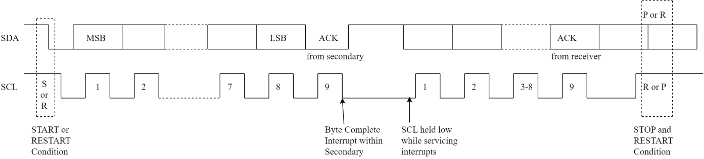
Figure: Typical I²C transfer showing SDA/SCL signals, START/STOP/RESTART conditions, and ACK/NACK pulses.
Key Features#
Flexible speed options
Supports all standard I²C speeds:Standard (100 kbps) for legacy sensors
Fast (400 kbps) for most modern peripherals
Fast-mode Plus (1 Mbps) for higher throughput
High-Speed mode (3.4 Mbps) for demanding applications
Leader or follower operation
Can act as the leader (controller) to manage connected peripherals, or as a follower (target) when another device controls the communication.
Multi-device communication
Supports 7-bit and 10-bit addressing, with combined-format transfers for mixed addressing schemes — enabling communication with multiple devices on the same bus.
Robust and reliable communication
Built-in clock synchronization and bus-clear features ensure stable operation, even on congested or noisy I²C lines.
Programmable SDA hold time helps maintain proper timing across a wide variety of I²C devices.
Efficient data handling
Integrated transmit and receive buffers reduce CPU load.
DMA support enables high-speed data transfers with minimal software overhead.
Bulk transmit mode in follower mode supports efficient large data transfers.
Flexible operation modes
Works in both interrupt-driven (low-latency, event-based) and polled (simpler implementation) modes.
Backward compatibility ensures smooth integration with legacy I²C devices (fast and high speed mode devices).
Low-power optimization
ULP I²C can continue transfers using DMA in PS2/PS1 low-power states, while the main processor is sleeping.
Extends battery life in IoT applications by allowing sensor polling without fully waking the MCU.
Architecture notes
The I²C block is attached to an AMBA APB register interface with FIFO logic to keep register access coherent with on-wire transfers.
I²C Software Architecture#
The SiWx917 I²C software architecture uses layered abstraction to provide clarity, modularity, and scalability for embedded development. The following figure shows the structure and flow.
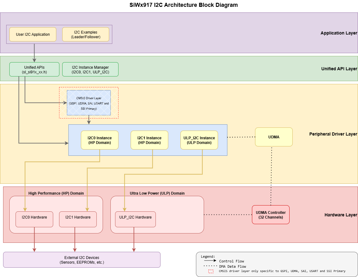
Figure: I²C software architecture.
Core Components#
Application Layer
The application code or the example projects that make I²C API calls (leader/follower use cases).Unified API Layer
High-level driver APIs for initialization, configuration, and data transfer.Peripheral Driver Layer
Low-level drivers that interact with the I²C hardware instances (I2C0, I2C1 in the HP domain and ULP_I2C in the ULP domain) via the registers.Hardware Layer
The physical I²C peripheral within the SiWx917 system on chip (SoC).
Note on CMSIS Layer
A generic CMSIS-Driver abstraction exists on this platform for some peripherals, but it does not apply to I²C here (kept in diagram for completeness).
How the layers work together#
Control path: App → Unified API → Peripheral driver → I²C instance (I2C0/I2C1/ULP_I2C).
Data path (optional): For larger writes, the driver programs UDMA so the controller can move bytes from memory to the I²C TX FIFO with minimal CPU work (TX-only DMA).
Design Benefits at a Glance#
Unified API hides hardware details so that the application code stays portable across I2C0, I2C1, and ULP_I2C.
Modular layering (App → API → Driver → Hardware) simplifies integration and long-term maintenance.
HP and ULP domains lets the application target either peak throughput (HP) or extended battery life (ULP) without changing app code.
UDMA integration enables efficient transfers with minimal CPU load.
Clear separation of concerns improves readability, makes extensions easier, and speeds up debugging.
Instance capabilities at a glance#
Instance | Domain | Max speed | DMA | Low-power behavior |
|---|---|---|---|---|
I2C0 / I2C1 | HP | Standard (100 kbit/s), Fast (400 kbit/s), Fast-mode Plus (Fm+, 1 Mbit/s), High-Speed (3.4 Mbit/s) | TX-only | Available in PS4/PS3 Active |
ULP_I2C | ULP | Standard (100 kbit/s), Fast (400 kbit/s) | TX-only | Available in the low-power domain (PS2 Active); suitable for low-power transfers |
Why This Matters to Your Application#
You call a single API; the driver selects the right instance and handles timing registers, FIFOs, and interrupts.
Use UDMA for bulk writes to reduce CPU load; for reads, rely on FIFO + IRQs (DMA is write/TX-only on I²C).
Choose ULP_I2C when you need periodic sensor writes while the M4 sleeps (PS1/PS2).
Directory Structure in WiSeConnect SDK#
wiseconnect/
├── components/
│ └── device/
│ └── silabs/
│ └── si91x/
│ └── mcu/
│ └── drivers/
│ ├── unified_peripheral_drivers/
│ │ ├── inc/
│ │ │ └── sl_si91x_peripheral_i2c.h
│ │ └── src/
│ │ └── sl_si91x_peripheral_i2c.c
│ └── unified_api/
│ ├── inc/
│ │ └── sl_si91x_i2c.h
│ └── src/
│ └── sl_si91x_i2c.c
├── examples/
│ └── si91x_soc/
│ └── peripheral/
│ ├── sl_si91x_i2c_driver_leader
│ ├── sl_si91x_i2c_driver_leader_using_transfer_api
│ ├── sl_si91x_i2c_driver_follower
│ └── sl_si91x_ulp_i2c_driver_leaderClock and Power Management#
On SiWx917, I²C clocks and power domains are managed by the platform. Peripherals are clock-gated by default, and the SDK enables what’s required when you add and configure an I²C component in Simplicity Studio.
High-performance I²C (I2C0, I2C1)
Available in PS4/PS3 Active. Use these instances when you need Fast-mode Plus (Fm+, 1 Mbit/s) or High-Speed (3.4 Mbit/s) data rates.Ultra-low-power I²C (ULP_I2C)
Available in PS4/PS3/PS2 Active and intended for battery-powered designs and other low-power use cases. Supports Standard (100 kbit/s) and Fast (400 kbit/s).
You typically don’t need to touch clock or power registers directly—WiSeConnect SDK and Simplicity Studio handle these details during component configuration.
For advanced use or troubleshooting, see the SiWx917 hardware reference manual, WiSeConnect SDK documentation, and the I²C low-power instance guide.
Power Domain Overview#
The SiWx917 SoC provides three I²C controllers, designed to balance performance and power efficiency.
I2C0 and I2C1 (High-performance domain)#
I2C0 (base address: 0x4401_0000)
I2C1 (base address: 0x4704_0000)
Available in active power states (PS4, PS3), these controllers support full-speed communication and are best suited for peripherals that require higher throughput or frequent data exchange (for example, displays, memory, or high-speed sensors).
Supports standard, fast, fast-mode plus, and high-speed modes (up to 3.4 Mbps)
ULP I²C (Ultra-low-power domain)#
ULP I²C (base address: 0x2404_0000)
Available in PS4, PS3, and PS2 states, this controller allows communication to continue even in lower power modes. It is ideal for battery-powered applications, periodic sensor polling, and always-on monitoring use cases.
Dependencies (Setup Checklist)#
Before using I²C on SiWx917, ensure the following:
WiSeConnect SDK (installed and configured in Simplicity Studio).
Simplicity Studio configuration; your
.slcpfile must include I²C components.Configure parameters (frequency, addressing mode, thresholds) using the Universal Configurator (UC).
Clock source and divider settings managed by the MCU clock architecture.
Power-state management; I²C availability depends on PS2, PS3, and PS4.
General-purpose input/output (GPIO) configuration; initialize SDA and SCL pins using
sl_si91x_i2c_pin_init().Place DMA buffers in ULP memory for best performance in low-power modes.
For detailed instructions on installation, configuration, and initialization, see the I²C initialization and configuration guide.