Set Up the Wi-SUN PHY Mode Switch Configuration#
Mode Switch Configuration with the Radio Configurator#
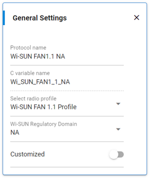
Once a new RAILtest project is created, the Radio Configurator opens automatically. You can then select the Wi-SUN FAN 1.1 Profile. The Radio Configurator provides a set of Wi-SUN FSK and OFDM PHYs as part of the Wi-SUN FAN 1.1 profile. The applicable Wi-SUN Regulatory Domain (for example NA, JP, EU, or BZ) according to Wi-SUN FAN 1.1 should be also selected.
To get a Mode Switch configuration between Wi-SUN PHYs, a channel-based multi-PHY configuration is required. More details on channel-based multi-PHY can be found in https://community.silabs.com/s/article/rail-tutorial-multi-phy-usecases-and-examples?language=en_US.
In the Radio Configurator, follow the steps below for an example for NA:
In the Protocol, select the Wi-SUN FAN 1.1 Profile and the Wi-SUN Regulatory Domain. In the following figure, the Wi-SUN NA Regulatory Domain is selected.
Update the default channel configuration. To get a Mode Switch configuration, you can add the PhyModeID as the MSByte of the channel number, which is on 2 bytes. This way, RAIL can associate each PhyModeID with a different channel number, which will be useful in Rx.
For example, a PhyModeID = 2 (2FSK mode 1b 50 kbps mi=1) provides a channel number of 0x0200=512, as shown.
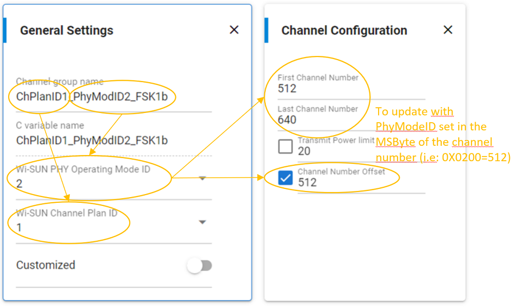
Note: The Wi-SUN Channel Plan ID list proposed depends on the Wi-SUN Regulatory Domain and on the selected Wi-SUN PHY Mode ID. The Wi-SUN Channel Plan ID selected supports automatically getting the base frequency and the channel spacing according to the Wi-SUN FAN 1.1 specification.
Add additional channel configurations for other PhyModeID using Create new channel:
Enter a Channel group name and the parameters as shown in the following example.
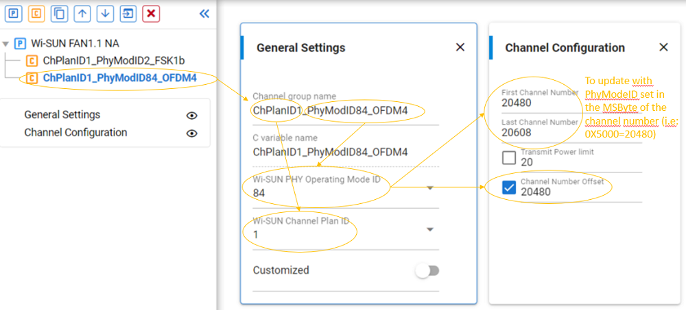
Add other channels and configure them as previously described for Mode Switch configuration. Use the following tables to compute the base channel number.
FSK PHY Mode References | FEC Enabled | FSK PhyModeID | Channel Number (MSByte = PhyModeID and first channel=0) |
|---|---|---|---|
#1a | no | 1 | 0x0100 = 256 |
#1b | no | 2 | 0X0200 = 512 |
#2a | no | 3 | 0x0300 = 768 |
#2b | no | 4 | 0x0400 = 1024 |
#3 | no | 5 | 0x0500 = 1280 |
#4a | no | 6 | 0x0600 = 1536 |
#4b | no | 7 | 0x0700 = 1792 |
#5 | no | 8 | 0x0800 = 2048 |
FSK PHY Mode References | FEC Enabled | FSK PhyModeID | Channel Number (MSByte = PhyModeID and first channel=0) |
|---|---|---|---|
#1a | yes | 17 | 0x1100 = 4352 |
#1b | yes | 18 | 0X1200 = 4608 |
#2a | yes | 19 | 0x1300 = 4864 |
#2b | yes | 20 | 0x1400 = 5120 |
#3 | yes | 21 | 0x1500 = 5376 |
#4a | yes | 22 | 0x1600 = 5632 |
#4b | yes | 23 | 0x1700 = 5888 |
#5 | yes | 24 | 0x1800 = 6144 |
Notes:
By default, the Mode Switch PPDU is always from an FSK to an FSK or an OFDM PhyModeID. Therefore, after a switch to an OFDM PhyModeID, the application should use the
setchannelRAILtest CLI command on both the Tx and Rx side to go back on an FSK PhyModeID. Alternatively, the RAILtest commandModeSwitchLife 1could be used (see The trigModeSwitchTx RAILtest CLI Command).Changing OFDM MCS within the same option does not require Mode Switch PPDU but only to set the MCS using
set802154phr.The OFDM PHY in the .radioconf file for Mode Switch only requires selecting the lowest MCS of the OFDM option available in the selected Wi-SUN Regulatory Domain as described below for the NA Regulatory Domain. Nevertheless, the MSByte of the channel number could use MCS0 PhyModeID.
OFDM Options | PhyModeID for MC0 | Channel Number (MSByte = PhyModeID and first channel=0) | PhyModeID with the lowest MCS for NA |
|---|---|---|---|
Option 1 | 0x20 = 32 | 0x2000 = 8192 | MCS2 0x22 = 34 |
Option 2 | 0x30 = 48 | 0x3000 = 12288 | MCS3 0x33 = 51 |
Option 3 | 0x40 = 64 | 0x4000 = 16384 | MCS4 0x44 = 68 |
Option 4 | 0x50 = 80 | 0x5000 = 20480 | MCS4 0x54 = 84 |
The set802154phr selects the MCS to be used and the PHYmodeID parameter in the trigModeSwitchTx selects the OFDM option, as described in Script Example.
Mode Switch radio_settings.radioconf Example for NA, JP, EU#
NA, JP, and EU Mode Switch radio_settings.radioconf file is provided as an example with this document. This section provides details on the radio configuration settings.
NA Wi-SUN Regulatory d=Domain#
For example, this Radio Configurator snapshot shows the Mode Switch Multi-PHY-based channel configuration for NA with Channel Plan ID 1, 2, 3, 4, and 5.
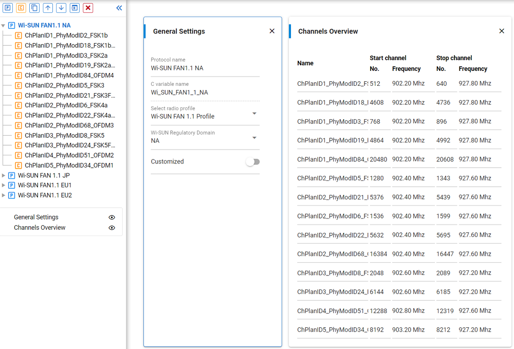
The Mode Switch configuration for the NA Regulatory Domain on configindex 0 is summarized in the following table.
| ChanPlanID | Base Frequency (Hz) | Channel Spacing (Hz) | PhyModeID | Channel Number (MSByte = PhyModeID and first channel=0) | Last Channel Number | PHY Modes References |
|---|---|---|---|---|---|---|
| 1 | 902200000 | 200000 | 2 | 0x0200 = 512 | 640 | #1b |
| 1 | 902200000 | 200000 | 18 | 0x1200 = 4608 | 4736 | #1b with FEC |
| 1 | 902200000 | 200000 | 3 | 0x0300 = 768 | 896 | #2a |
| 1 | 902200000 | 200000 | 19 | 0x1300 = 4864 | 4992 | #2a with FEC |
| 1 | 902200000 | 200000 | 80 | 0x5000 = 20480 | 20608 | OFDM Option 4 MCS set with set802154phr |
| 2 | 902400000 | 400000 | 5 | 0x0500 = 1280 | 1343 | #3 |
| 2 | 902400000 | 400000 | 21 | 0x1500 = 5376 | 5439 | #3 with FEC |
| 2 | 902400000 | 400000 | 6 | 0x0600 = 1536 | 1599 | #4a |
| 2 | 902400000 | 400000 | 22 | 0x1600 = 5632 | 5695 | #4a with FEC |
| 2 | 902400000 | 400000 | 64 | 0x4000 = 16384 | 16447 | OFDM Option 3 MCS set with set802154phr |
| 3 | 902600000 | 600000 | 8 | 0x0800 = 2048 | 2089 | #5 |
| 3 | 902600000 | 600000 | 24 | 0x1800 = 6144 | 6185 | #5 with FEC |
| 4 | 902800000 | 800000 | 48 | 0X3000 = 12288 | 12319 | OFDM Option 2 MCS set with set802154phr |
| 5 | 903200000 | 1200000 | 32 | 0x2000 = 8192 | 8212 | OFDM Option 1 MCS set with set802154phr |
Mode switch can be enabled across all PHYs specified in the PhyModeID column.
JP Wi-SUN Regulatory Domain
This Radio Configurator snapshot shows the Mode Switch Multi-PHY-based channel configuration for JP with Channel Plan ID 21, 22, 23, and 24.
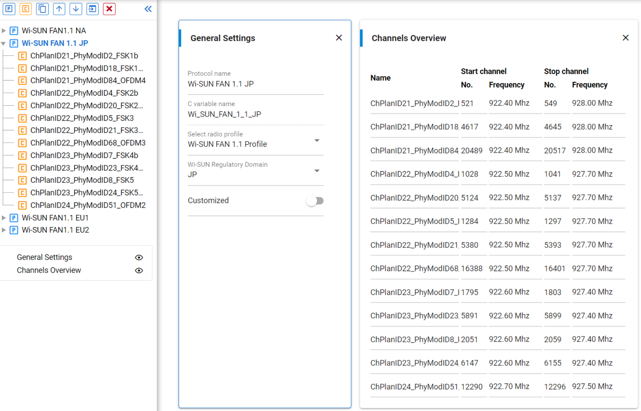
The Mode Switch configuration for the JP Regulatory Domain on configindex 1 is summarized in the following table.
| ChanPlanID | Base Frequency (Hz) | Channel Spacing (Hz) | PhyModeID | Channel Number (MSByte = PhyModeID and first channel=0) | First Channel Number (not masked) | Last Channel Number | PHY Modes References |
|---|---|---|---|---|---|---|---|
| 21 | 920600000 | 200000 | 2 | 0x0200 = 512 | 521 | 549 | #1b |
| 21 | 920600000 | 200000 | 18 | 0x1200 = 4608 | 4617 | 4645 | #1b with FEC |
| 21 | 920600000 | 200000 | 80 | 0x5000 = 20480 | 20489 | 20517 | OFDM Option 4 MCS set with set802154phr |
| 22 | 920900000 | 400000 | 4 | 0x0400 = 1024 | 1028 | 1041 | #2b |
| 22 | 920900000 | 400000 | 20 | 0x1400 = 5120 | 5124 | 5137 | #2b with FEC |
| 22 | 920900000 | 400000 | 5 | 0x0500 = 1280 | 1284 | 1297 | #3 |
| 22 | 920900000 | 400000 | 21 | 0x1500 = 5376 | 5380 | 5393 | #3 with FEC |
| 22 | 920900000 | 400000 | 64 | 0x4000 = 16384 | 16388 | 16401 | OFDM Option 3 MCS set with set802154phr |
| 23 | 920800000 | 600000 | 7 | 0x0700 = 1792 | 1795 | 1803 | #4b |
| 23 | 920800000 | 600000 | 23 | 0x1700 = 5888 | 5891 | 5899 | #4b with FEC |
| 23 | 920800000 | 600000 | 8 | 0x0800 = 2048 | 2051 | 2059 | #5 |
| 23 | 920800000 | 600000 | 24 | 0x1800 = 6144 | 6147 | 6155 | #5 with FEC |
| 24 | 921100000 | 800000 | 48 | 0X3000 = 12288 | 12290 | 12296 | OFDM Option 2 MCS set with set802154phr |
Mode switch can be enabled across all PHYs specified in the PhyModeID column.
Note: In Japan, a channel mask applies and forbids the use of the lower channels. The First Channel number (not masked) column indicates the first valid channel that can be used.
EU Wi-SUN Regulatory Domain Case 1#
This Radio Configurator snapshot shows the Mode Switch Multi-PHY-based channel configuration for EU1. In this example, EU 1 includes both 863-870 MHz and 863-876 MHz bands, resulting in Channel Plan IDs 32, 33, 36, and 37, as shown.
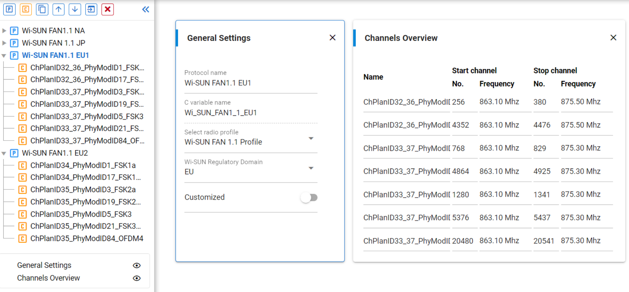
Note the ChanPlanID32 and 36 have the same configuration except that ChanPlanID36 uses the maximum number of channels. The same is true for ChanPlanID33 and 37.
The mode switch configuration for the EU Regulatory Domain on configindex 2 is summarized in the following table.
| ChanPlanID | Base Frequency (Hz) | Channel Spacing (Hz) | PhyModeID | Channel Number (MSByte = PhyModeID and first channel=0) | First Channel Number | Last Channel Number | PHY Modes References |
|---|---|---|---|---|---|---|---|
| 32 | 863100000 | 100000 | 1 | 0x0100 = 256 | 256 | 324 | #1a |
| 32 | 863100000 | 100000 | 17 | 0x1100 = 4352 | 4352 | 4420 | #1a with FEC |
| 33 | 863100000 | 200000 | 3 | 0x0300 = 768 | 768 | 802 | #2a |
| 33 | 863100000 | 200000 | 19 | 0x1300 = 4864 | 4864 | 4898 | #2a with FEC |
| 33 | 863100000 | 200000 | 5 | 0x0500 = 1280 | 1280 | 1314 | #3 |
| 33 | 863100000 | 200000 | 21 | 0x1500 = 5376 | 5376 | 5410 | #3 with FEC |
| 33 | 863100000 | 200000 | 80 | 0x5000 = 20480 | 20480 | 20514 | OFDM Option 4 MCS set with set802154phr |
| 36 | 863100000 | 100000 | 1 | 0x0100 = 256 | 256 | 380 | #1a |
| 36 | 863100000 | 100000 | 17 | 0x1100 = 4352 | 4352 | 4476 | #1a with FEC |
| 37 | 863100000 | 200000 | 3 | 0x0300 = 768 | 768 | 829 | #2a |
| 37 | 863100000 | 200000 | 19 | 0x1300 = 4864 | 4864 | 4925 | #2a with FEC |
| 37 | 863100000 | 200000 | 5 | 0x0500 = 1280 | 1280 | 1341 | #3 |
| 37 | 863100000 | 200000 | 21 | 0x1500 = 5376 | 5376 | 5437 | #3 with FEC |
| 37 | 863100000 | 200000 | 80 | 0x5000 = 20480 | 20480 | 20541 | OFDM Option 4 MCS set with set802154phr |
Mode switch can be enabled across all PHYs specified in the PhyModeID column.
Note: In EU, a channel mask applies and forbids the use of some available channels in the middle and at the end of the RF band. The channel masking in the middle of the RF band is taken into account for Mode Switch thanks to a RAIL callback provided by the stack (see RAIL_lib API Usage for Mode Switch PPDU).
EU Wi-SUN Regulatory Domain Case 2#
This Radio Configurator snapshot shows the Mode Switch Multi-PHY-based channel configuration for EU2 (870-876 MHz) with Channel Plan ID 34 and 35.
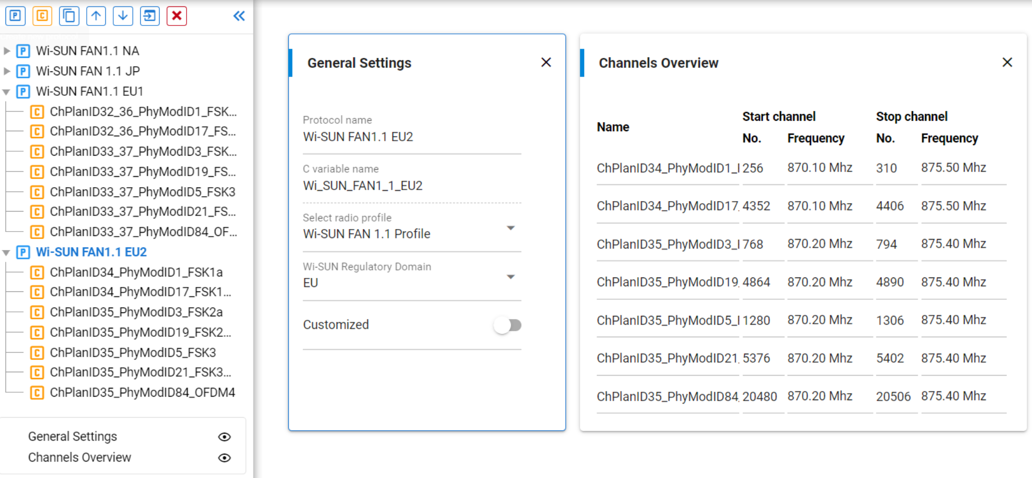
The Mode Switch configuration for the EU Regulatory Domain on configindex 3 is summarized in the following table.
| ChanPlanID | Base frequency (Hz) | Channel spacing (Hz) | PhyModeID | Channel number (MSByte = PhyModeID and first channel=0) | First Channel number | Last Channel number | PHY modes References |
|---|---|---|---|---|---|---|---|
| 34 | 870100000 | 100000 | 1 | 0x0100 = 256 | 256 | 310 | #1a |
| 34 | 870100000 | 100000 | 17 | 0x1100 = 4352 | 4352 | 4406 | #1a with FEC |
| 35 | 870200000 | 200000 | 3 | 0x0300 = 768 | 768 | 794 | #2a |
| 35 | 870200000 | 200000 | 19 | 0x1300 = 4864 | 4864 | 4890 | #2a with FEC |
| 35 | 870200000 | 200000 | 5 | 0x0500 = 1280 | 1280 | 1306 | #3 |
| 35 | 870200000 | 200000 | 21 | 0x1500 = 5376 | 5376 | 5402 | #3 with FEC |
| 35 | 870200000 | 200000 | 80 | 0x5000 = 20480 | 20480 | 20506 | OFDM Option 4 MCS set with set802154phr |
Mode switch can be enabled across all PHYs specified in the PhyModeID column.
Note: In EU, a channel mask applies and forbids the use of some available channels in the middle and at the end of the RF band. The channel masking in the middle of the RF band is taken into account for Mode Switch thanks to a RAIL callback provided by the stack (see RAIL_lib API Usage for Mode Switch PPDU).