About Crystal Tolerances#
The precision of the system crystal in a radio system, such as the Z-Wave radio system, is vital. If the transmitters and receivers in the Radio system are not operating with the correct clock frequency, and if the frequency difference between the parts is large, it will affect the obtainable range between the parts. This leads to customers experiencing a bad performance of the radio system. It is therefore mandatory to make sure that the system frequency of a radio product is as accurate as possible and adheres to the specifications of the radio protocol used, in this case, the Z-Wave protocol.
The total tolerance of a crystal is a sum of three contributions:
Initial tolerances
Temperature tolerances
Aging tolerances
For the Z-Wave protocol, the required tolerances for the crystal after five years of operation is ±27 ppm.
To avoid frequency harmonics in any Z-Wave frequency band, only a 39 MHz crystal is supported. The crystal requirements for EFR32ZG14 and EFR32ZG23 are provided in the table below.
Chipset | Frequency | Total Tolerance | Load Capacitance (CL) | Shunt Capacitance (C0) | ESR |
|---|---|---|---|---|---|
EFR32ZG14 | 39 MHz | ±27 ppm | 6-12 pF | Typically 2-3 pF | Max. 60 Ω |
EFR32ZG23 | 39 MHz | ±27 ppm | 10 pF | Typically 2-3 pF | Max. 60 Ω |
The recommended crystal parts for EFR32ZG14 and EFR32ZG23 are provided in the table below.
Chipset | Crystal Manufacturer | Crystal Part Number | ESR (Ω) | C0 (max) (pF) | Temp (°C) | Temp Tolerance (ppm) | Mfg Tolerance (ppm) | Aging (ppm) | CL (pF) | Footprint (mm) |
|---|---|---|---|---|---|---|---|---|---|---|
EFR32ZG14 | TXC | 8Y39072002 | 35 | 1 | -40 to +95 | ±13 | ±7 | ±2 | 10 | 2.0 x 1.6 |
EFR32ZG23 | Tai-Saw | TZ3541C | 35 | 2 | 0 to +50 | ±16 | ±8 | ±3 | 10 | 2.0 x 1.6 |
Note: The crystal parts in this table are the ones used for validation and characterization of the specific Z-Wave devices. However, both parts meet the crystal requirements for EFR32ZG14 and EFR32ZG23 (see the table above). Therefore, both can be used with any of these Z-Wave devices. List of alternative crystal parts can be found in Second Source Crystal Components.
The Initial tolerances are affected by:
Parasitic load capacitance at the crystal component connections
Parasitic load of the Z-Wave SoC
Pressure exerted on the component package
The Temperature tolerances are affected by:
The temperature of the environment
The Aging tolerances are affected by:
Overdrive of the crystal
Overheat of the component
Mechanical stress due to normal usage
If it is assumed that the crystal is not stressed in any way, not mechanically nor electrically, there are two parameters left, which can give a tolerance change for the crystal, i.e., change the frequency of the crystal. These parameters are: the parasitic load capacitance added by the PCB of the product and the differences of the load capacitance of the crystal oscillators for the individual Z-Wave SoCs.
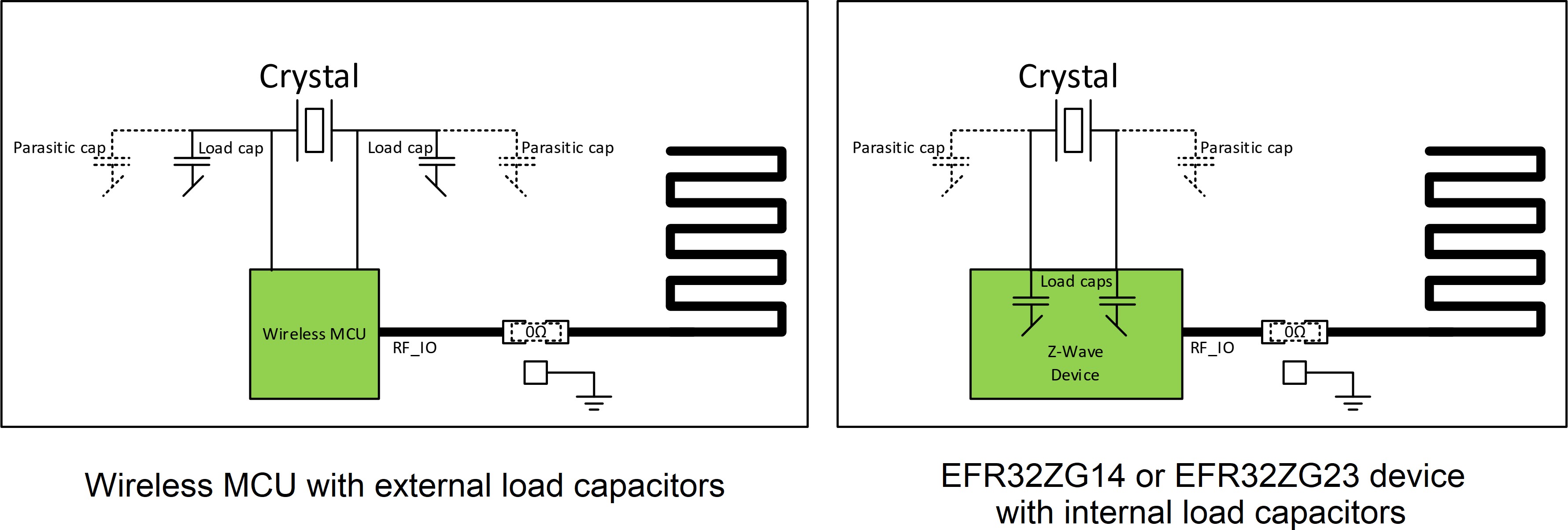
Depending on the implementation of the crystal oscillator circuit of an SoC, external load-caps may be required. However, this is not the case for the EFR32ZG14 or the EFR32ZG23 devices, where the load-caps are integrated on the die of the chipsets, as illustrated in the figure below:
The amount of parasitic capacitance seen by the crystal depends on:
Trace length
PCB material properties
Differences in the internal size of the SoC load caps
These parameters vary from product-design to product-design and from Z-Wave SoC to Z-Wave SoC.
To counteract the parasitic load capacitance of the PCB, device implementation, and Z-Wave SoCs, the Z-Wave protocol offers the possibility to adjust the internal load capacitances in such a way that the total capacitance seen by the crystal fulfills the crystal specifications.