Using RAILtest#
As mentioned in Bringing Up Z-Wave Hardware in General, RAILtest is a software tool distributed as part of the Z-Wave software offering, through which you can setup various parameters relevant for both RF regulatory testing and for hardware bring-up and validation tests:
PA output power setting
Crystal fine-adjustment
Transmission of CW
Transmission of Z-Wave frames
Reception of Z-Wave frames
Finding the LBT threshold
Scripting of RAILtest
When using RAILtest, a special Z-Wave application is not required for the hardware developer to bring-up a product and validate it. The usage of RAILtest thus decouples the software development phase from the hardware bring-up phase.
Compiling RAILtest#
RAILtest is part of the Z-Wave software distribution. It is an example project which needs to be compiled to a binary file, ready to be downloaded to the product using a tool such as Simplicity Commander (refer to [1]).
There are two versions of RAILtest for 700 series:
RAILtest for ZGM130S devices
RAILtest for EFR32ZG14 devices
There are two versions of RAILtest for 800 series:
RAILtest for ZGM230S devices
RAILtest for EFR32ZG23 devices
The correct RAILtest version for the correct Z-Wave device must be used in the product.
How to compile RAILtest is described in the RAILtest User's Guide. It is most important to select a UART buffer size of 128 bytes and to enable scripting in Flash.
Interfacing to RAILtest#
As described in How to Interface the Z-Wave Product During the Bring-Up Phase of the Project, RAILtest uses UART lines for communication, which means that a computer with a terminal program is needed to be able to control and use RAILtest. The serial settings must be:
Baudrate: 115.2kBaud
No parity
8 databits
1 stopbit
No handshake
Starting RAILtest#
Once connected to the product, and after having downloaded RAILtest and started the terminal program on the computer, RAILtest outputs information on both the display of the BRD4001A WSTK board and on the UART:

The program is now ready for input.
Initially, RAILtest enables the device in receive mode at a non-Z-Wave frequency and setting. This setting needs to be changed.
Getting Help in RAILtest#
RAILtest has a build in Help Menu. The Help Menu is shown using the command help:
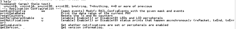
The Help Menu will show all the capabilities of RAILtest. Many of these are not relevant for Z-Wave applications, and only the relevant ones are described in this document.
Setting Up the Z-Wave Environment for RAILtest#
Follow the steps below to change to Z-Wave mode:
Disable the initial receiver mode.
Set up Z-Wave mode.
Set up Z-Wave packets.
Set up Z-Wave region.
Set up Z-Wave channel number.
Once this is done, you must decide if a transmission of Z-Wave frames, a CW transmission, or reception of Z-Wave frames is needed.
The following sections will show how to setup RAILtest for various user-scenarios. All RAILtest parameters will be written with the Courier font and enclosed with ''. Comments are preceded with two semi-colons, such as ;; Comment.
How to Adjust the PA Output Power Using RAILtest#
RAILtest can be used to set the RF output level of the PA. The ability to adjust the PA output power is required to pass RF regulatory tests, where one of the key measurements is to ensure, that the level of RF power transmitted is at or below the required limits.
The RAILtest command used to set up the output power is:
'SetPower yy raw' ;; Set PA output power to setting number yy
Refer to How to Setup for CW Transmission, No SAW Filter/One SAW Filter below and How to Set Up for CW Transmission with a SAW Filter Bank (700 Series Only) for examples, where this command is used.
The number yy is a decimal number ranging from 0 to 155 for the 700 series and from 0 to 200 for the 800 series, where 0 is the lowest possible power setting and 155/200 is the highest possible power setting.
Note: The RF PA power cannot be adjusted unless the device is in idle mode; that is, the command
rx 0must have been issued and the device may not be in any kind of transmit mode.
How to Setup for CW Transmission, No SAW Filter/One SAW Filter#
This section describes how to use RAILtest for setting up a CW transmission and for adjusting the PA output power on products with one or no SAW filters:
'rx 0 ;; Set device in idle state
'SetZwaveMode 1 3' ;; Setup for Z-Wave operation
'SetTxLength 20' ;; Setup TX frame length
'SetTxPayload 7 20' ;; Setup payload type and length
'setzwaveregion x' ;; Setup Z-Wave region to number x, please see below
'SetPower yy raw' ;; Set PA output power to setting number yy
'setchannel z' ;; Set Z-Wave channel number to z
'settxtone 1' ;; Enable the CWThe number x for Z-Wave regions can be a number ranging from 0 to 13 (refer to the table below). The Z-Wave frequencies for each region can be found in [2].
Region Number | Region Location | Saw Filter Region |
|---|---|---|
0 | EU-European Union | E |
1 | US-United States | U |
2 | ANZ-Australia/New Zealand | H |
3 | HK-Hong Kong | H |
4 | Non-Valid Z-Wave region* | |
5 | IN-India | E |
6 | JP-Japan | H |
7 | RU-Russia | E |
8 | IL-Israel | U |
9 | KR-Korea | H |
10 | CN-China | E |
11 | Z-Wave Long Range region 1 | U |
12 | Z-Wave Long Range region 2 | U |
13 | Z-Wave Long Range End Device | U |
* This Z-Wave region is no longer valid to use.
According to the table above, the command setzwaveregion 0 would enable the device for usage in countries following the European RF legislation.
The output of the PA is regulated using the command setPower yy raw and the value yy is a number ranging from 0 to 155 for 700 series and 0 to 200 for 800 series. The higher a number, the more output power; the lower a number, the less output power.
The Z-Wave channel is set up using the command setchannel z, and the value z is a number ranging from 0 to 3. Channel and baud-rate are tied together as shown in the table below.
Channel Number | Channel Speed [1] |
|---|---|
0 | 100 kBit/s GFSK |
1 | 40 kBit/s FSK |
2 | 9.6 kBit/s FSK |
3 [2] | 100 kBit/s OQPSK |
Notes:
Channel speeds shown are not valid for JP and KR regions. In those regions, all channel speeds are 100 kBit/s GFSK.
Channel 3 is only available for regions 11 and 12, the Z-Wave Long Range "controller" regions.
The frequency of the CW is determined by (1) The Z-Wave region selected and (2) The Z-Wave channel selected within the Z-Wave region.
So, if transmission is to be tested on the European frequency 868.42 MHz, which is the 9.6 kBit/s channel, the channel number must be set to 2. And if transmission to be tested is at 912 MHz, which is the Z-Wave Long Range channel, then the region number is 11 and the channel number must be set to 3.
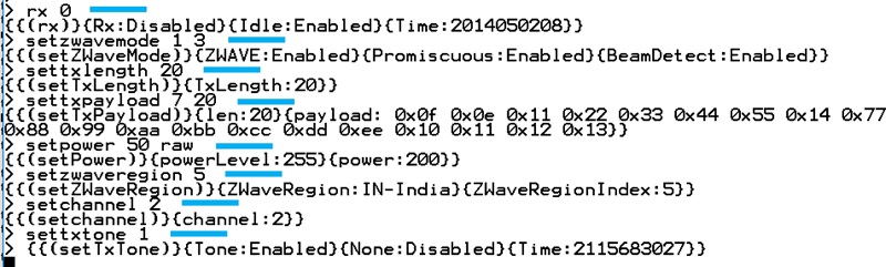
Below is an example where a device is initialized to transmit a CW at the Indian channel 2. The input commands to RAILtest are marked with a blue line next to the command:
Note: The product will continue to transmit a CW until the command
settxtone 0is issued.
How to Set Up for CW Transmission with a SAW Filter Bank (700 Series Only)#
For products with multiple SAW filters, the correct SAW filter must be selected by setting the appropriate GPIO pins of the Z-Wave 700 device. Below is an example which can be used if the product is configured like the BRD4200A or BRD4201A Z-Wave 700 development boards. For these boards, PB14 and PB15 are used to select which SAW filter to use:
SAW Filter Region | PB14 | PB15 |
|---|---|---|
H | 0 | 0 |
E | 1 | 0 |
U | 0 | 1 |
'rx 0' ;; Disable receiver mode
'SetZwaveMode 1 3' ;; Setup for Z-Wave operation
'SetTxLength 20' ;; Setup TX frame length
'SetTxPayload 7 20' ;; Setup payload type and length
'setzwaveregion x' ;; Setup Z-Wave region to number x
'SetPower yy raw' ;; Set PA output power to setting number yy
'setchannel z' ;; Set Z-Wave channel number to z
'setGPIOoutPin B 14 m' ;; Set state of PB14 GPIO, m =[0,1]
'setGPIOoutPin B 15 n' ;; set state of PB15 GPIO, n =[0,1]
'settxtone 1' ;; Enable the CWFor a description of the number for the Z-Wave regions, refer to the Z-Wave Region Numbers table in How to Setup for CW Transmission, No SAW Filter/One SAW Filter above. For a description of the Z-Wave channels, refer to the Channel Speed table in the same section above.
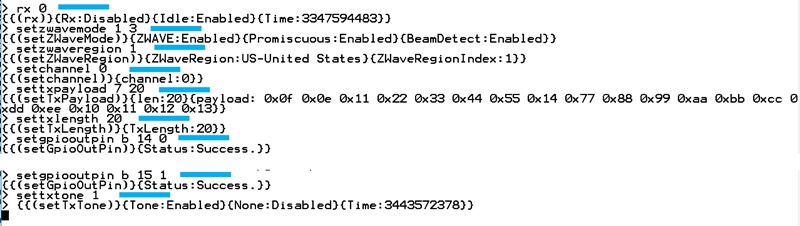
Below is an example where the product has a SAW filter bank like the one used on the BRD4200A / BRD4201A boards and the CW must be set to the US channel 0. The input commands are marked with blue line next to the command:
If the PA power needs to be adjusted, this must be done prior to enabling the CW using the command setpower xx raw, where xx is a number ranging from 0 to 155.
Note: The product will continue to transmit a CW until the command
settxtone 0is issued.Note: The selection of a SAW filter in a SAW filter bank depends on how the SAW filter bank is implemented in the product.
How to Set Up for Transmitting Z-Wave Frames#
RAILtest can transmit Z-Wave frames formatted according to the Z-Wave specification. This can be very useful in connection with sensitivity measurements or when the RF regulatory authorities measure the bandwidth of the Z-Wave radio channels.
Setting up for Z-Wave frame transmission is almost identical to setting up for CW transmission, except for the last command, which in this case is not settxtone 1 but instead tx x, where x is a number. If the number is 0, a continuous stream of Z-Wave frames will be transmitted until the command tx 0 is issued again. If the number is not 0, then the number reflects how many Z-Wave frames should be transmitted.
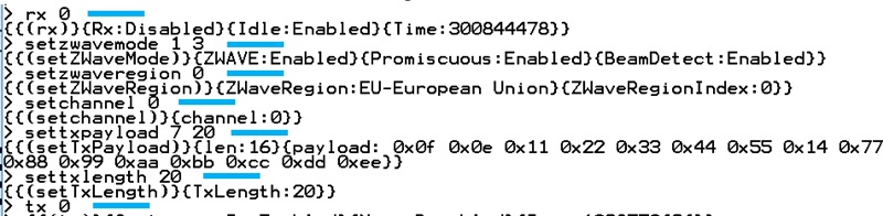
Below is an example where a product with only one or zero SAW filters is enabled for transmitting Z-Wave frames with a length of 20 bytes at the Z-Wave region 0 channel 0, which according to Z-Wave Region Numbers and Channel Speed tables above, is the EU region 100 kBit/s channel:
'rx 0' ;; disable RX mode
'setzwavemode 1 3' ;; Setup Z-Wave mode
'setzwaveregion 0' ;; Setup Z-Wave region 0, EU
'setchannel 0' ;; Setup Z-Wave channel 0, 100 kBit/s channel
'settxpayload 7 20' ;; Setup payload type and payload length
'settxlength 20' ;; Setup payload length
'tx 0' ;; Start endless transmission of framesFor a description of the number for the Z-Wave regions, refer to the Z-Wave Region Numbers table in How to Setup for CW Transmission, No SAW Filter/One SAW Filter above. For a description of the Z-Wave channels, refer to the Channel Speed table in the same section above.
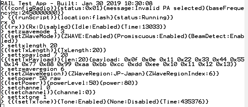
Below is an example of how RAILtest responds to the commands described above. The input commands to RAILtest are marked with a blue line to the right of the command:
Note: To stop the transmission of Z-Wave frames, re-issue the command
tx 0.
If the Z-Wave 700 product has multiple SAW filters, use the same method as described in section How to Set Up for CW Transmission with a SAW Filter Bank (700 Series Only). Use the commands setGPIOoutPin B 14 m and setGPIOoutPin B 15 n according to the table in How to Set Up for CW Transmission with a SAW Filter Bank (700 Series Only).
How to Set Up for Reception of Z-Wave Frames for a 700 Series Device#
RAILtest can receive and decode Z-Wave frames according to the Z-Wave specification. This can be very useful in connection with sensitivity measurements.
When setting up for Z-Wave reception, the setup is a bit more complicated compared to the transmission setup.
Below is an example where a product with only one or zero SAW filters is enabled for receiving Z-Wave frames with a length of 60 bytes at the Z-Wave region 0, which according to the Z-Wave Region Numbers table, is the EU region. Note that setting up a channel is not needed because the Z-Wave 700 device will scan all three Z-Wave channels for valid Z-Wave traffic.
'rx 0' ;; Disable RX
'SetZwaveMode 1 3' ;; Setup for Z-Wave mode
'SetTxLength 60' ;; Setup Z-Wave frame length
'SetTxPayload 7 60' ;; Setup Z-Wave frame length and type
'setzwaveregion 0' ;; Setup Z-Wave region
'configRXChannelHopping x1 x2 x3 x4 x5 x6 x7 x8 x9 x10 x11 x12' ;; Ch setup
'enableRxChannelHopping 1' ;; Enable multi scanning mode
'rx 1' ;; Enable reception of Z-Wave framesThe values for the demodulator settings x1 to x12 must be setup according to the table below.
| Region | X1 | X2 | X3 | X4 | X5 | X6 | X7 | X8 | X9 | X10 | X11 | X12 |
|---|---|---|---|---|---|---|---|---|---|---|---|---|
| 0 | 0 | 3 | 270 | 0 | 1 | 3 | 450 | 0 | 2 | 3 | 560 | 0 |
| 1 | 0 | 3 | 270 | 0 | 1 | 3 | 450 | 0 | 2 | 3 | 560 | 0 |
| 2 | 0 | 3 | 270 | 0 | 1 | 3 | 450 | 0 | 2 | 3 | 560 | 0 |
| 3 | 0 | 3 | 270 | 0 | 1 | 3 | 450 | 0 | 2 | 3 | 560 | 0 |
| 41 | 0 | 3 | 270 | 0 | 1 | 3 | 450 | 0 | 2 | 3 | 560 | 0 |
| 5 | 0 | 3 | 270 | 0 | 1 | 3 | 450 | 0 | 2 | 3 | 560 | 0 |
| 6 | 0 | 3 | 270 | 0 | 1 | 3 | 270 | 0 | 2 | 3 | 270 | 0 |
| 7 | 0 | 3 | 270 | 0 | 1 | 3 | 450 | 0 | 2 | 3 | 560 | 0 |
| 8 | 0 | 3 | 270 | 0 | 1 | 3 | 450 | 0 | 2 | 3 | 560 | 0 |
| 9 | 0 | 3 | 270 | 0 | 1 | 3 | 270 | 0 | 2 | 3 | 270 | 0 |
| 10 | 0 | 3 | 270 | 0 | 1 | 3 | 450 | 0 | 2 | 3 | 560 | 0 |
1: The highlighted row indicates that region 4 is an invalid Z-Wave region. See the Z-Wave Region Numbers table.
Below is an example of how RAILtest responds to the commands described above. The RAILtest commands are marked with a blue line:
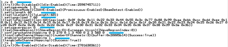
The parameters for the channel hopping settings are found in the Multi-Channel Settings table above. It is very important to use the correct settings for the selected Z-Wave region.
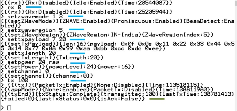
Once the receiver is setup and enabled, the product will start to receive any Z-Wave frame correctly formatted according to the Z-Wave specification. An example of received Z-Wave frames due to the setup described are shown in the figure below.
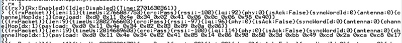
The figure above shows how RAILtest presents the reception of three different Z-Wave frames. Right after the enabling of the receiver, the command rx 1, a Z-Wave frame with the length of 11 bytes is received. A time stamp is given, the CRC value of the Z-Wave frame is validated, the incoming RSSI level is stated, and then the payload of the frame is written. Next, a frame of 9 bytes is received, followed by a frame with the length of 19.
So even though a Z-Wave frame length of 60 was set up, all frames are received, validated, and decoded.
If the Z-Wave 700 product has multiple SAW filters, and a SAW filter must be selected, use the same method as described in How to Set Up for CW Transmission with a SAW Filter Bank ( Series Only) and use the commands setGPIOoutPin B 14 m and setGPIOoutPin B 15 n according to the SAW Filter Selection Settings table in that section.
How to Set Up for Reception of Z-Wave Frames for an 800 Series Device#
Setting up an 800 series device differs from setting up a 700 series device.
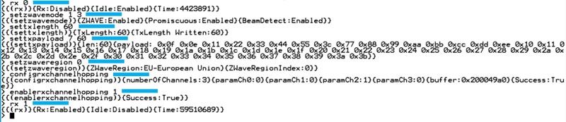
Below is an example where a product is enabled for receiving Z-Wave frames with a length of 60 bytes at the Z-Wave region 0, which according to the Z-Wave Region Numbers table, is the EU region. Note that setting up a channel is not needed because the Z-Wave 800 device will scan all three Z-Wave channels for valid Z-Wave traffic.
'rx 0' ;; Disable RX
'SetZwaveMode 1 3' ;; Setup for Z-Wave mode
'SetTxLength 60' ;; Setup Z-Wave frame length
'SetTxPayload 7 60' ;; Setup Z-Wave frame length and type
'setzwaveregion 0' ;; Setup Z-Wave region
'configRxChannelHopping' ;; Ch setup
'enableRxChannelHopping 1' ;; Enable multi scanning mode
'rx 1' ;; Enable reception of Z-Wave framesBelow is an example of how RAILtest responds to the commands described above. The RAILtest commands are marked with a blue line.
How to Set Up for Reception of Z-Wave Long Range Frames on a 700 Series Device#
Setting up RAILtest for reception and decoding of Z-Wave Long Range frames according to the Z-Wave specification. This can be very useful in connection with sensitivity measurements.
When setting up for Z-Wave Long Range reception, the setup is a bit more complicated compared to the transmission setup and to the setup of reception of "normal" Z-Wave. There are two different Z-Wave Long Range modes, controller mode and end-device mode, and both differ from the description shown in How to Set Up for Reception of Z-Wave Frames fora 700 Series Device.
The channel hopping options for Z-Wave Long Range are shown in the table below.
| Region | 11 | 12 | 13 |
|---|---|---|---|
| X1 | 0 | 0 | 0 |
| X2 | 131 | 131 | 2 |
| X3 | 290 | 290 | 300 |
| X4 | 0 | 0 | 0 |
| X5 | 1 | 1 | 1 |
| X6 | 131 | 131 | 2 |
| X7 | 340 | 340 | 300 |
| X8 | 0 | 0 | 0 |
| X9 | 2 | 2 | |
| X10 | 131 | 131 | |
| X11 | 580 | 580 | |
| X12 | 0 | 0 | |
| X13 | 3 | 3 | |
| X14 | 2 | 2 | |
| X15 | 300 | 300 | |
| X16 | 0 | 0 |
Reception of Frames for Z-Wave Long Range Regions 11 and 12#
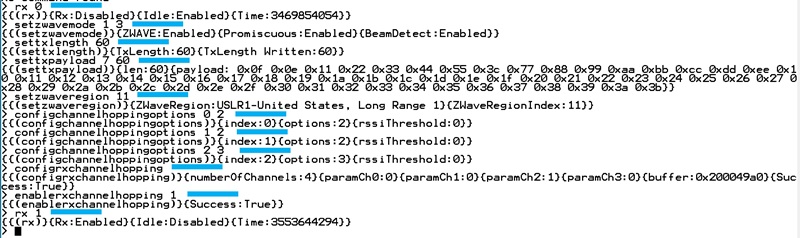
Below is an example where a product with no SAW filters is enabled for receiving Z-Wave Long Range frames with a length of 60 bytes at the Z-Wave region 11, which according to the Z-Wave Region Numbers table, is the US Long Range region 1. Note that setting up a channel is not needed because the Z-Wave 700 device will scan all four Z-Wave channels for valid Z-Wave traffic.
'rx 0' ;; Disable RX
'SetZwaveMode 1 3' ;; Setup for Z-Wave mode
'SetTxLength 60' ;; Setup Z-Wave frame length
'SetTxPayload 7 60' ;; Setup Z-Wave frame length and type
'setzwaveregion 11' ;; Setup Z-Wave Long Range region
'configChannelHoppingOptions 0 2' ;; Setup hopping options
'configChannelHoppingOptions 1 2' ;; Setup hopping options
'configChannelHoppingOptions 2 3' ;; Setup hopping options
'configRXChannelHopping x1 x2 x3 x4 x5 x6 x7 x8 x9 x10 x11 x12 x13 x14 x15 x16' ;; Ch setup
'enableRxChannelHopping 1' ;; Enable multi scanning mode
'rx 1' ;; Enable reception of Z-Wave framesThe values for the demodulator settings x1 to x16 must be setup according to the Multi-Channel Settings for ZWLR table in How to Set Up for Reception of Z-Wave Long Range Frames on a 700 Series Device.
Below is an example of how RAILtest responds to the commands described above. The RAILtest commands are marked with a blue line.
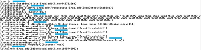
The parameters for the channel hopping settings are found in the Multi-Channel Settings for ZWLR table in How to Set Up for Reception of Z-Wave Long Range Frames on a 700 Series Device. It is very important to use the correct settings for the selected Z-Wave Long Range region.
Reception of Frames for Z-Wave Long Range Region 13#
Below is an example where a product with no SAW filters is enabled for receiving Z-Wave Long Range frames with a length of 60 bytes at the Z-Wave region 13, which according to the Z-Wave Region Numbers table, is the US Long Range region for end-devices. Note that setting up a channel is not needed because the Z-Wave 700 device will scan all four Z-Wave channels for valid Z-Wave traffic:
'rx 0' ;; Disable RX
'SetZwaveMode 1 3' ;; Setup for Z-Wave mode
'SetTxLength 60' ;; Setup Z-Wave frame length
'SetTxPayload 7 60' ;; Setup Z-Wave frame length and type
’setzwaveregion 13' ;; Setup Z-Wave Long Range region
'configRXChannelHopping x1 x2 x3 x4 x5 x6 x7 x8' ;; Ch setup
'enableRxChannelHopping 1' ;; Enable multi scanning mode
'rx 1' ;; Enable reception of Z-Wave framesThe values for the demodulator settings x1 to x8 must be setup according to the Multi-Channel Settings for ZWLR table in How to Set Up for Reception of Z-Wave Long Range Frames on a 700 Series Device.
Below is an example of how RAILtest responds to the commands described above. The RAILtest commands are marked with a blue line.
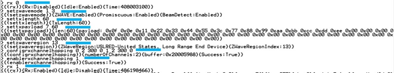
The parameters for the channel hopping settings are found in the Multi-Channel Settings for ZWLR table in How to Set Up for Reception of Z-Wave Long Range Frames on a 700 Series Device. It is very important to use the correct settings for the selected Z-Wave Long Range region.
How to Set Up for Reception of Z-Wave Long Range Frames on an 800 Series Device#
Setting up RAILtest for reception and decoding of Z-Wave Long Range frames according to the Z-Wave specification differs between the 700 series and the 800 series.
When setting up for Z-Wave Long Range reception, the setup is a bit more complicated compared to the transmission setup and to the setup of reception of "normal" Z-Wave. There are two different Z-Wave Long Range modes, controller mode and end-device mode, and both differ from the description shown in How to Set Up for Reception of Z-Wave Long Range Frames on a 700 Series Device
Reception of Frames for Z-Wave Long Range Regions 11 and 12#
Below is an example where a product is enabled for receiving Z-Wave Long Range frames with a length of 60 bytes at the Z-Wave region 11, which according to the Z-Wave Region Numbers table, is the US Long Range region 1. Note that setting up a channel is not needed because the Z-Wave 800 device will scan all four Z-Wave channels for valid Z-Wave traffic.
'rx 0' ;; Disable RX
'SetZwaveMode 1 3' ;; Setup for Z-Wave mode
'SetTxLength 60' ;; Setup Z-Wave frame length
'SetTxPayload 7 60' ;; Setup Z-Wave frame length and type
’setzwaveregion 11' ;; Setup Z-Wave Long Range region
’configChannelHoppingOptions 0 2' ;; Setup hopping options
’configChannelHoppingOptions 1 2' ;; Setup hopping options
’configChannelHoppingOptions 2 3' ;; Setup hopping options
'configRXChannelHopping' ;; Ch setup
'enableRxChannelHopping 1' ;; Enable multi scanning mode
'rx 1' ;; Enable reception of Z-Wave framesBelow is an example of how RAILtest responds to the commands described above. The RAILtest commands are marked with a blue line.
Reception of Frames for Z-Wave Long Range Region 13#
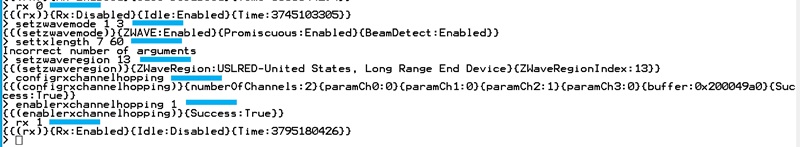
Below is an example where a product is enabled for receiving Z-Wave Long Range frames with a length of 60 bytes at the Z-Wave region 13, which according to the Z-Wave Region Numbers table, is the US Long Range region for end-devices. Note that setting up a channel is not needed because the Z-Wave 800 device will scan all four Z-Wave channels for valid Z-Wave traffic.
'rx 0' ;; Disable RX
'SetZwaveMode 1 3' ;; Setup for Z-Wave mode
'SetTxLength 60' ;; Setup Z-Wave frame length
'SetTxPayload 7 60' ;; Setup Z-Wave frame length and type
'SetZwaveRegion 13' ;; Setup Z-Wave Long Range region
'configRXChannelHopping' ;; Ch setup
'enableRxChannelHopping 1' ;; Enable multi scanning mode
'rx 1' ;; Enable reception of Z-Wave framesThe values for the demodulator settings x1 to x8 must be setup according to the Multi-Channel Settings for ZWLR table in How to Set Up for Reception of Z-Wave Long Range Frames on a 700 Series Device.
Below is an example of how RAILtest responds to the commands described above. The RAILtest commands are marked with a blue line.
Reception of Z-Wave Long Range Frames#
Once the receiver is setup and enabled, the product will start to receive any Z-Wave frame correctly formatted according to the Z-Wave and Z-Wave Long Range specification. An example of received Z-Wave frames due to the setup described are shown in the figure below.

The figure above shows how RAILtest presents the reception of two different Z-Wave frames. Right after the enabling of the receiver, the command rx 1, a Z-Wave frame with the length of 34 bytes is received. A time stamp is given, the CRC value of the Z-Wave frame is validated, the incoming RSSI level is stated, the channel hop ID is given, and then the payload of the frame is written. Next, a frame of 43 bytes is received, and this frame is received at another hop index than the previous.
So even though a Z-Wave frame length of 60 was set up, all frames at all channels within a region are received, validated, and decoded.
If the Z-Wave 700 product has multiple SAW filters, and a SAW filter must be selected, use the same method as described in How to Set Up for CW Transmission with a SAW Filter Bank (700 Series Only) and use the commands setGPIOoutPin B 14 m and setGPIOoutPin B 15 n according to the SAW Filter Selection Settings table in How to Set Up for CW Transmission with a SAW Filter Bank (700 Series Only)
How to Fine-Tune the System Crystal Using RAILtest#
For EFR32ZG14 SoCs#
As mentioned in How to Adjust RF Parameters to Get the Best Possible Performance of the Product, the RF system frequency must be adjusted and it is strongly recommended for EFR32ZG14 devices to compensate for the parasitic load capacitance added by the products PCB to the system crystal.
The adjustment procedure is a two-step process:
Establish the RF frequency offset.
Adjust and remeasure the RF frequency offset.
For item #1, generating an RF CW is needed. How to generate a CW using RAILtest is described in either section How to Setup for CW Transmission, No SAW Filter/One SAW Filter or How to Set Up for CW Transmission with a SAW Filter Bank (700 Series Only).
Once the product is transmitting a CW, the frequency of the CW must be measured with a precise and newly calibrated spectrum analyzer. The frequency span of the spectrum analyzer should be set to no more than 100 kHz with a low resolution bandwidth in order to be able to measure the small frequency changes introduced by the crystal frequency adjustments.
The frequency measured on the products must be recorded for later comparison purposes.
Once the frequency of the board is recorded, the adjustment process can start. Assuming the TxTune being turned on, use the following RAILtest commands.
'setTxTone 0' ;; Disable the TxTone
'rx 0' ;; Set the system in idle
'getCtune' ;; Read the current CTune value
'setCtune 0xYYY' ;; Set a new CTune value
'setTxTone 1' ;; Re-enable the TxTone againThe command getctune is used to find the initial setting for the product. This number will be given as a hexadecimal number, hence the notation 0xYYY.
An iterative process now starts. It is strongly advised to only change the value of CTune in small increments, e.g. change the CTune value 2 digits up or down. With the new CTune setting 0xYYY, a new frequency measurement should be performed to verify if the CW frequency is adjusted to the target frequency.
An example of a frequency adjustment cycle is shown below. In the example, the target frequency is 908.42 MHz, since the Z-Wave region is selected to 1 and the channel number is set to 2. For reference, see the Z-Wave Region Numbers and Channel Speed tables. The product does not have a switchable SAW filter bank. The RAILtest commands are marked with a blue line to the right of the command.
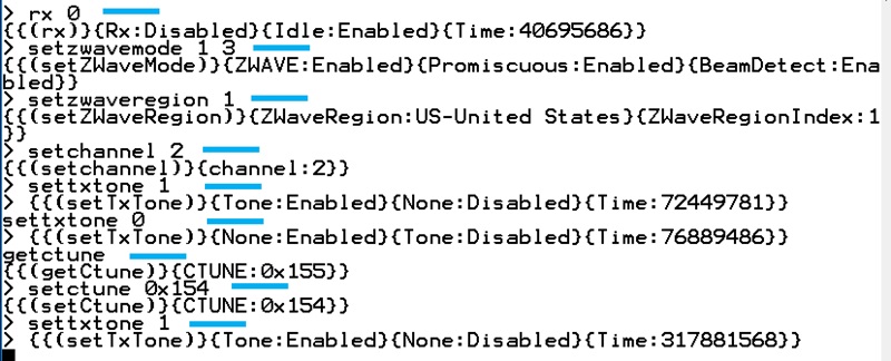
If the CW is adjusted to be within 1ppm, no further adjustments are needed.
Note: Due to the inherent tolerances of crystals, only a "pr. Product" fine-adjustment/calibration will eliminate the frequency offset for each individual product.
For ZGM130S SiP modules#
Since the ZGM130S devices are frequency calibrated during the manufacturing process, no frequency adjustment is needed to obtain a precise RF frequency. However, RAILtest does not automatically use the CTune value found during the calibration. If there is a need to fine-tune a ZGM130S based product during the usage of RAILtest, follow the procedure shown below.
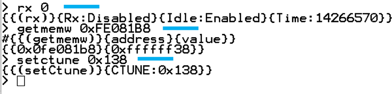
'rx 0' ;; Set device in idle
'getmemw 0xFE081B8' ;; Read crystal calibration value from ZGM130S
'setctune 0xZZZ' ;; write the calibration value to RAILtestThe value 0xZZZ depends on the value return by the memory read operation getmemw. The CTune value 0xZZZ is equal to a binary AND operation of the returned memory content.
CTune = Returned result of getmemw 0xFE081B8 & 0x1FF
Example:
The getmemw returns the hexadecimal value 0xffffff38.
The CTune value to write is:
CTune = 0xffffff38 & 0x1ff => Ctune = 0x138
An example of how to read back the calibration value for the system crystal in RAILtest is shown below. The RAILtest commands are marked with a blue line to the right of the command.
For EFR32ZG23 SoCs#
As mentioned in How to Adjust RF Parameters to Get the Best Possible Performance of the Product, the RF system frequency must be adjusted and it is strongly recommended for Z-Wave EFR32ZG23 devices to compensate for the parasitic load capacitance added by the products PCB to the system crystal.
The adjustment procedure is a two-step process:
Establish the RF frequency offset.
Adjust and remeasure the RF frequency offset.
For item #1, generating an RF CW is needed. How to generate a CW using RAILtest is described in either How to Setup for CW Transmission, No SAW Filter/One SAW Filter or How to Set Up for CW Transmission with a SAW Filter Bank (700 Series Only).
Once the product is transmitting a CW, the frequency of the CW must be measured with a precise and newly calibrated spectrum analyzer. The frequency span of the spectrum analyzer should be set to no more than 100 kHz with a low resolution bandwidth in order to be able to measure the small frequency changes introduced by the crystal frequency adjustments.
The frequency measured on the products must be recorded for later comparison purposes.
Once the frequency of the board is recorded, the adjustment process can start. Assuming the TxTune being turned on, use the following RAILtest commands.
'setTxTone 0' ;; Disable the TxTone
'rx 0' ;; Set the system in idle
'getCtune' ;; Read the current CTune value
'setCtune 0xYY' ;; Set a new CTune value
'setTxTone 1' ;; Re-enable the TxTone againThe command getctune is used to find the initial setting for the product. This number will be given as a hexadecimal number with the notation CTUNEXIANA: 0xYY (Two numbers are returned {CTUNEXIANA:0x0YY}{CTUNEXOANA:0x0ZZ}, but only the CTUNEXIANA is important for the C-tuning).
An iterative process now starts. It is strongly advised to only change the value of CTune in small increments, e.g. change the CTune value 2 digits up or down. With the new CTune setting 0xYY, a new frequency measurement should be performed to verify if the CW frequency is adjusted to the target frequency.
An example of a frequency adjustment cycle is shown below. In the example, the target frequency is 908.42 MHz, since the Z-Wave region is selected to 1 and the channel number is set to 2. For reference, see the Z-Wave Region Numbers and Channel Speed tables. The product does not have a switchable SAW filter bank. The RAILtest commands are marked with a blue line to the right of the command.
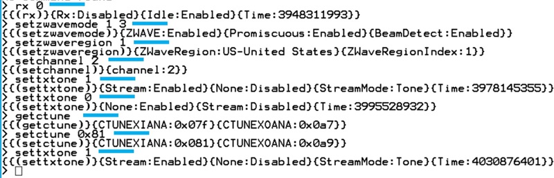
In the example above, the CTune value was read back as 0x07F and adjusted to 0x081. If the CW is adjusted to be within 1ppm, no further adjustments are needed.
Note: Due to the inherent tolerances of crystals, only a “pr. Product” fine-adjustment/calibration will eliminate the frequency offset for each individual product.
For ZGM230S SiP Modules#
Since the ZGM230S devices are frequency calibrated during the manufacturing process, no frequency adjustment is needed to obtain a precise RF frequency.
How to Perform a Sensitivity Measurement Using RAILtest#
A sensitivity measurement is the most vital measurement which can be performed on a wireless product. It shows the RF qualities of the product, and for wireless enabled products, the RF qualities will define the overall customer experience of the product:
The better sensitivity, the better a range between nodes in a Z-Wave network
Better coverage with fewer devices
Better range means fewer repeater devices in the Z-Wave network
Less cost for the customer
Lower network latency
With better sensitivity, frames do not need to be re-transmitted and hence less power is needed.
For sensor products, limiting the number of re-transmissions conserves the battery
There are two ways of conducting sensitivity measurements:
Wired
Wireless
Wired Sensitivity Measurements#
For a wired sensitivity measurement, the DUT is connected to a Z-Wave frame transmitter through coax wires, and an adjustable RF attenuator is inserted in between the Z-Wave frame transmitter and the DUT. The Z-Wave frame generator could be a Z-Wave 700 (BRD4206A, BRD4207A) or 800 (BRD4204D, BRD4210A, BRD4205B) development board mounted on a BRD4001A WSTK and flash-ed with RAILtest:
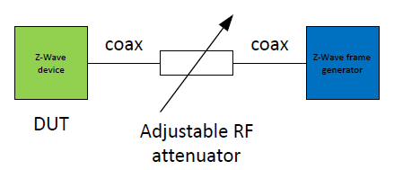
For each part of the setup shown in the figure above, a control unit is required, e.g. for the Z-Wave device, a computer must be connected to the product in order to configure RAILtest. For the adjustable RF attenuator, either a test operator must adjust the RF attenuation or an automatic RF attenuator can be used, and for the Z-Wave Frame generator, control unit is needed as well.
Note: To avoid cross-hearing between the Z-Wave device and the Z-Wave frame generator it is recommended to lower the output power of the Z-Wave transmitters to e.g. -10dBm or even lower. An alternative is to place the Z-Wave device in a radio-shielded box.
Once the setup is created, you can perform the test as described below.
Set up both transmitter and receiver to the correct Z-Wave settings, as described in sections How to Set Up for Transmitting Z-Wave Frames, How to Set Up for Reception of Z-Wave Frames for a 700 Series Device, or How to Set Up for Reception of Z-Wave Frames for an 800 Series Device.
Set the RF attenuator to setting X, initially e.g. -50dB.
Enable the DUT for reception.
Transmit 1000 frames.
Use RAILtest to analyze how many of the 1000 frames were correctly received by the DUT.
Reset the receive counters in the DUT.
Decrease the RF attenuator value with 1 dB, to e.g. -51dB.
Jump to #3 until less than 990 frames are received by the DUT. Using above described test method will test for a 1% packet error level.
The method to set up a device for Z-Wave frame reception is shown in How to Set Up for Reception of Z-Wave Frames for a Series Device / How to Set Up for Reception of Z-Wave Frames for an 800 Series Device. Apart from this set up, RAILtest’s status function can be used to evaluate the number of correctly received frames. The commands to use are:
'rx 0' ;; Disable reception
'status' ;; Get frame reception status
'resetCounters' ;; Reset frame status counters
'rx 1' ;; Enable reception for new attenuator settingBelow is an example, where the DUT is set up for reception of Z-Wave frames in the Indian region using a Z-Wave device series 700. The product is setup for reception, reception is enabled, status is asked for, the counters are cleared, and the device is re-enabled for another RF attenuator setting. Each RAILtest command is marked with a blue line to the right of the command.
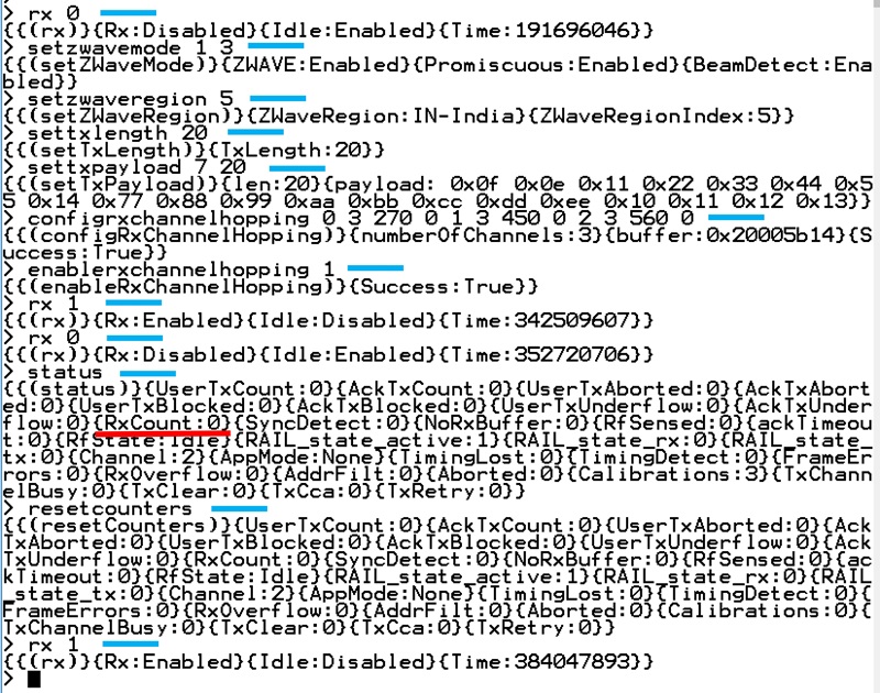
The figure above shows the output of the status command, and there are many parameters being written by RAILtest. The important number to notice is the {RxCount} number, underlined with red, in the figure above.
Note: The equivalent setup-sequence for a Z-Wave device series 800 would be identical except for the configrxchannelhopping command which does not need any parameters, refer to How to Set Up for Reception of Z-Wave Frames for an Series Device.
If the transmitter has been started with the command tx 1000, 1000 frames are transmitted. Once the transmission is done, the receiver is disabled with the rx 0 command, the command status is issued on the DUT, and if the reading of the RxCount value is 1000, like {RxCount : 1000}, all of the transmitted frames were received. If the reading is less, Z-Wave frames were lost due to a less optimal RF channel between the Z-Wave frame transmitter and the DUT.
Note: One does not need to set up any channel number in the receiver, since the receiver will scan all the RF channels for the Z-Wave region.
The method for setting up the transmitter for Z-Wave frame transmission is shown in How to Set Up for Transmitting Z-Wave Frames. To test all the Z-Wave channels within the Z-Wave region, it is important that each channel number, ranging from 0 to 2, is used in the transmitter setup and the sensitivity test. Below, all RAILtest commands are marked with a blue line to the right of the command.
When the command tx xxx is issued, immediately the response from the RAILtest will be what is shown in the figure above at the {{(tx)} transmit information} information. Once the transmission of the 100 frames is done, the RAILtest will show the line marked with the green line, starting with {{(txEnd)} transmitted information}. When this line is observed on the UART output from the Z-Wave frame generator, the receiver is then ready for a status reading using the command status.
Note: It is most important to know the RF loss in the sensitivity measurement setup. This can be found by replacing the DUT shown in the figure in Wired Sensitivity Measurements with a spectrum analyzer, setting the RF attenuator to 0 dB, and transmitting a CW from the Z-Wave frame transmitter. The RF power measured by the spectrum analyzer can be used to calculate the sensitivity as:
Example:
A spectrum analyzer is inserted instead of the DUT, the RF attenuator is adjusted to 0 dB attenuation, and the measured power at this RF attenuator setting is -20 dBm.
The following sensitivity measurement shows that there is a 1% packet error level at an attenuator setting of 80 dB.
What is the sensitivity of the system?
If the 1% packet error level was measured at an RF attenuator setting = -82 dB, the sensitivity of the system is -102 dBm.
To avoid interference from the environment during the sensitivity measurements, it is strongly recommended to perform the measurements in a radio shielded environment, such as an RF shielded room, or by placing the receiver inside an RF shielded box. It is further advised to use a low PA setting for the Z-Wave frame transmitter to avoid any cross radiation directly from the PCB of the Z-Wave frame generator to the PCB of the DUT.
Radiated Sensitivity Measurements#
A radiated sensitivity measurement is the most representative use-case measurement which can be performed because the DUT is used and tested just like the end-user of the product would experience it.
Reliable and trustworthy radiated measurements can only be conducted if:
The radiated measurement setup is performed under strictly controlled manners inside an anechoic chamber and a Total Isotropic Sensitivity test is conducted.
The radiated test is performed on a huge open field, high above the ground, and with no nearby constructions to reflect or transmit RF energy.
For normal urban areas in which a test would typically be conducted, the results from a radiated sensitivity measurement cannot be trusted or reproduced because:
RF channel will be strongly dependent on the environment:
Buildings
Reflections from objects
Reflections from the ground
Weather conditions, if test is performed on an open field
RF channel will be strongly dependent on the exact positions of the DUT and the Z-Wave frame generator.
Note: A radiated sensitivity measurement can give an indication of the line-of-sight range.
The RAILtest setup method for the radiated sensitivity / range measurement is almost identical to the setup described in Wired Sensitivity Measurements. For the DUT, the method would be identical, but for the Z-Wave frame generator, decreasing the PA setting is not recommended. Instead, the planned PA setting must be used.
The figure below shows a simple radiated setup.
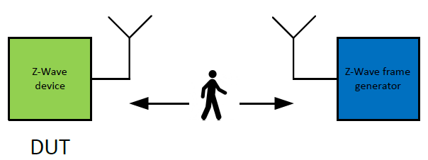
Either the DUT or the Z-Wave frame generator is placed in a fixed location, and the distance between the DUT and the Z-Wave frame generator is gradually increased, with one set of frame transmission pr. distance-increment. Once the number of received frames has dropped by 1%, the pathloss due to the distance is equivalent to the sensitivity limit of the product.
The distance can also be increased until no frames are received at all. This would be the maximum line of sight distance that can be obtained with the DUT under the given conditions.
How to Find the LBT Threshold#
This section describes how to use a RAILtest for 800 series products when finding the LBT threshold for either the Japanese or the Korean Z-Wave region.
'rx 0' ;; Set device in idle state
'SetZwaveMode 1 3' ;; Setup for Z-Wave operation
'SetTxLength 20' ;; Setup TX frame length
'SetTxPayload 7 20' ;; Setup payload type and length
'setzwaveregion x' ;; Setup Z-Wave region to number x, see Table 1
'configRXChannelHopping' ;; Ch setup
'enableRxChannelHopping 1' ;; Enable multi scanning mode
'SetPower yy raw' ;; Set PA output power to setting number yy
'setLbtParams L1 L2 L3 L4 L5 L6 L7' ;; Set LBT params and threshold see ;; Table 6
'setLbtMode csma' ;; Set detection method
'configTxOptions 64' ;; Setup transmitter options
'rx 1' ;; Enable reception and apply RF noise
'getRssi' ;; Read RSSI value for RF noise at threshold
'rx 0' ;; Set device in idle state
'setLbtParams L1 L2 L3 L4 L5 L6 L7' ;; Set LBT params and threshold
'rx 1' ;; Enable device in RX mode
'tx xx' ;; Transmit xx number of framesThe parameters for the command setLbtParams are shown in the table below (Z-Wave LBT Settings).
Note: Z-Wave device series 700 has an identical setup sequence except for the command
configRXChannelHopping, which needs the parameters from the Multi-Channel Settings table in How to Set Up for Reception of Z-Wave Frames for a 700 Series Device.
Z-Wave LBT Settings
| Region Number | L1 | L2 | L3 | L4 | L5 | L6 | L7 |
|---|---|---|---|---|---|---|---|
| 6 (Japan) | 2 | 2 | 15 | RSSIJapan | 750 | 128 | 200000 |
| 9 (Korea) | 2 | 2 | 15 | RSSIKorea | 750 | 5000 | 200000 |
The purpose of this measurement is to find the number for the parameter L4. This value will vary from Z-Wave region to Z-Wave region and from product design to product design.
Above, the device is initialized to transmit Z-Wave frames with a length of 20 bytes for a certain Z-Wave region. The PA output power is set to a value, yy, and the channel is selected to 0. For this measurement, it does not matter if the channel is set to 0, 1, or 2. The LBT parameters are then initialized, the collision avoidance is selected to type csma, and a TX option is set to 64.
Next the parameter L4 must be found, and this is done by connecting the Z-Wave product to an RF generator using a wired connection, i.e., a coax cable, setting the output power of the RF generator to the RF regulation limit (for Japan -80 dBm and for Korea -65 dBm), and enabling an RF CW at the frequency of the channel. The Z-Wave device is now exposed to an amount of RF energy identical to the LBT noise level as required by the RF regulatory authorities.
With the CW applied to the Z-Wave product, the Z-Wave product is configured to be in receive mode, and an RSSI reading is performed using the RAILtest command getRssi. The found RSSI value is identical to the LBT threshold L4. For a conservative approach, it is advised to set the LBT threshold 1 dB below the found RSSI in order to have some margin in the threshold.
With L4 found, the LBT parameters are re-initialized with the expected value for L4 and a test can be performed as described below:
Turn off the RF output of the connected RF generator.
Transmit XX number of frames using the command
tx XX.Upon end of transmission, write the statistical values for the number of transmitted frames to the terminal. The number of frames transmitted must match the number of frames used in the command
tx XX. For example, if the commandtx 2was used, the status must show that 2 frames were transmitted.Enable the RF generator and set the RF output power to the level which matches the LBT threshold required.
Transmit a number of frames.
At the end of transmission, the number of frames transmitted should be 0 and the number of failed transmissions should be identical to the number of frames used in the command in item #5.
Adjust the output power of the RF generator up and down and check that the LBT threshold is set correct.
Note: For Z-Wave 700 products with a SAW filter or a SAW filter bank, the procedure described is identical except for the fact that for SAW filter bank products one must select the correct SAW as described in How to Set Up for CW Transmission with a SAW Filter Bank (700 Series Only).
The figure below shows an example where the LBT threshold is to be found for a device in the Z-Wave region 6, Japan. RAILtest commands are underlined in blue and important results are underlined in orange. Information on enabling or disabling the RF generator used to create the noise in the channel are marked with a red box.
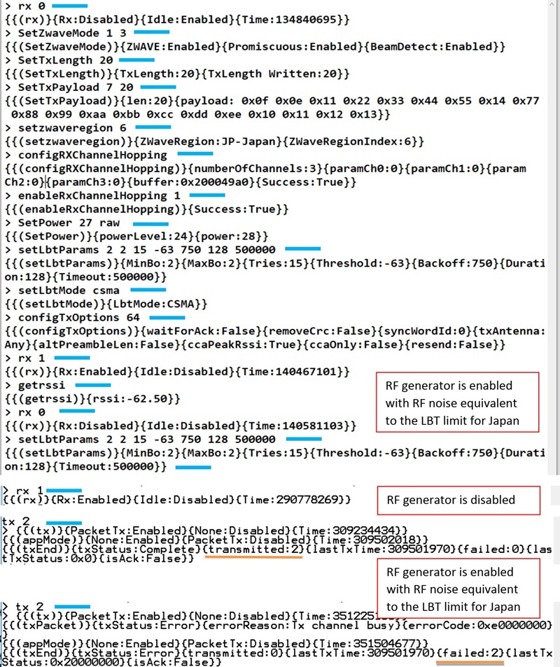
The red boxes in the figure above indicate when to turn on and off the RF generator that creates the noise floor for the RSSI measurement and the following LBT measurement.
In the example, only two frames are transmitted and used to verify if the LBT threshold is correctly set up. It is strongly recommended to use a larger number of frames for this test to increase the statistical validity of the LBT threshold setting.
It may be an iterative process to find the exact LBT value. For good measurements and to add a bit of margin to the LBT threshold, it is advised to add a dB to the threshold value as a margin.
The value found for L4 must be used in the Z-Wave protocol as described below:
For EFR32ZG14 and EFR32ZG23 SoCs: LBT threshold value must be used in connection with FUNC_ID_ZW_SET_LISTEN_BEFORE_TALK_THRESHOLD
For ZGM130S and ZGM230S SiP modules: LBT threshold value must be used in connection with the command EZWAVECOMMANDTYPE_ZW_SET_LBT_THRESHOLD
Note: It is very important to perform the LBT measurements with a calibrated setup, that is, all cable losses must be accounted for when setting the level of the RF generator to the LBT noise level.
Scripting RAILtest#
For some products, it may be impractical, or even impossible, to submit a product to the RF regulatory authorities if the only means of controlling the product is through a UART terminal interface, as described in Starting RAILtest.
The UART terminal interface may be impractical for the test house to handle.
The UART terminal interface may completely change the radiation pattern of the product and, thus, give a wrong impression of how the product performs.
The test house may not be trusted to correctly setup the device before the RF regulatory tests.
To accommodate for any of above situations, RAILtest can be scripted in such a way that the Z-Wave device stores the RAILtest instructions in the internal flash memory and then retrieves and initializes the Z-Wave device with the stored settings upon reset or re-power.
This means that it will be possible to set up, validate, and ship fully pre-configured products for RF regulatory tests without having the RF regulatory test house do anything else but apply power to the product under test.
This following section describes how to enable the script mode, enter a script, validate a script, and exit script mode.
Note: A permanent UART connection-means to the Z-Wave device in the product is still strongly advised, refer to Interfacing to RAILtest, since the scripting of the Z-Wave device is done through the UART interface of the Z-Wave device. But once set up, the UART connections used can be removed from the product to ensure that the appearance of the product is as uninterrupted as possible.
Workflow for Script Mode#
To be able to use RAILtest in a scripted mode, you must:
Establish power, programming, and UART connections to the product as shown in How to Interface the Z-Wave Product During the Bring-Up Phase of the Project.
Download RAILtest to the product as described in Compiling RAILtest.
Interface to the UART of the Z-Wave device as described in Interfacing to RAILtest.
Initialize scripting mode.
Enter the script.
Exit script mode.
Re-power the product.
Test the functionality of the script.
Power off the product.
Remove the UART and the programming connections to the Z-Wave device.
A script can at any time be changed or removed by re-connecting the Z-Wave device of the product to its UART connections and then either delete or change the script.
How to Start, Exit, and Erase a Script#
RAILtest can store commands in the flash memory and retrieve these commands upon a reset of a power-off/on event. This can be very useful in connection with pre-configuration of products which must be submitted to RF regulatory tests.
Below is an example where scripting is enabled and disabled:
'enterscript 1' ;; Enable script mode, save in flash
'endscript' ;; End script mode / clear scriptThe first command enterscript 1 enables scripting mode, and the 1 means that the script is stored in the flash memory of the Z-Wave device.
In the above example, the script is immediately terminated using the command endscript. When written as above, both script-mode is terminated and an eventual script stored will be erased from the flash memory of the Z-Wave device.
Notice that the first command written enterscript 1 must be followed by a "Return" character, where as the last command written endscript activates once the letter t is typed.
The figure below shows an example, where script mode is entered and immediately terminated again.
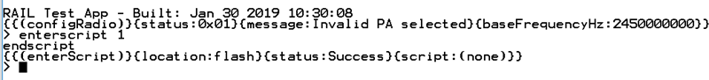
Note: When the command
enterscript 1is directly followed byendscript, the content of the flash memory is erased and Script mode is disabled.
setTxTone Script#
RAILtest can handle the same commands in Scripting mode as it can through the interactive CLI previously described in the sections Setting Up the Z-Wave Environment for RAILtest through How to Read UUID of a 800 Series Device. Finding and setting the LBT threshold is an interactive operation and is not well suited for Scripting mode.
Below is an example, where the Z-Wave device is setup to transmit a CW tone:
'enterscript 1' ;; Enable script mode, store in flash
'rx 0' ;; Disable RX
'SetZwaveMode 1 3' ;; Setup for Z-Wave operation
'SetTxLength 20' ;; Setup payload length
'SetTxPayload 7 20' ;; Setup payload type and length
'setzwaveregion 6' ;; Setup Z-Wave region, Japan
'SetPower 50 raw' ;; Setup output power
'setchannel 0' ;; Setup Z-Wave channel
'settxtone 1' ;; Enable CW
'endscript' ;; Store script in flash and endWhen comparing the script above with the similar operation performed through the interactive CLI as described in Setting Up the Z-Wave Environment for RAILtest, notice that the only difference between the commands are the enterscript 1 and the endscript.
The figure below shows an example where the above script is typed into RAILtest. RAILtest commands are marked with blue.
Scripting setTXTone
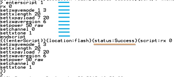
Notice that when in Script mode, commands are not acknowledged by RAILtest.
When the letter t in the command endscript is typed, the status of the Script operation is shown as well as the content of the script stored. The Script is now stored in the flash memory.
When the Z-Wave device is either reset or power-cycled, the content of the Script will be executed. Refer to the figure below (Execution of setTxTone script) to see what RAILtest outputs when the script from the Scripting setTXTone figure above is executed by means of a reset pulse.
Execution of setTxTone script
Notice that each of the command lines are acknowledged by RAILtest as if they were directly typed on the CLI.
Note: It is only after a reset / power-cycle event that the validity of a Script can be proven. So all Scripts should be validated by means of a reset event, followed by a visual inspection of the RAILtest outputs as well as a functional test by means of a measurement.
RX Mode Script#
If the LO leakage is to be measured by the RF regulatory authorities, this can be done by entering a Script in the Z-Wave device of the product, and all the authorities must do is apply power to the product and measure the LO leakage. No interaction with the product will be needed.
Below is an example where the Z-Wave device is initialized for RX operation:
'enterscript 1' ;; Enter Script mode
'rx 0' ;; Disable RX mode
'SetZwaveMode 1 3' ;; Setup for Z-Wave mode
'setzwaveregion 6' ;; Setup Z-Wave region, Japan
'setchannel 0' ;; Setup channel 0
'rx 1' ;; Enable RX mode
'endscript' ;; Exit script modeThe figure below shows an example where the above script is typed into RAILtest. RAILtest commands are marked with blue.
Scripting RX Mode
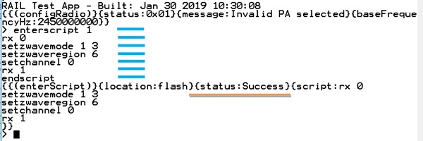
Notice that when in Script mode, commands are not acknowledged by RAILtest.
When the letter t in the command endscript is typed, the status of the script operation is shown as well as the content of the script stored. The script is now stored in the flash memory.
When the Z-Wave device is either reset or power-cycled, the content of the script will be executed. Refer to the figure below (Execution of RX Mode Script) to see what RAILtest outputs when the script from the Scripting RX Mode above is executed by means of a reset pulse.
Execution of RX Mode Script
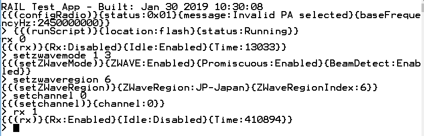
Notice that each of the command lines are acknowledged by RAILtest as if they were directly typed on the CLI.
Note: It is only after a reset / power-cycle event that the validity of a Script can be proven. So all Scripts should be validated by means of a reset event, followed by a visual inspection of the RAILtest outputs as well as a functional test by means of a measurement.
How to Read UUID of a 700 Series Device#
Each Z-Wave device is programmed with a unique UUID during the manufacturing of the device. This UUID can be used to track the device, correlate production test measurements with the individual devices, or for other purposes.
RAILtest can be used to read the UUID from the Z-Wave device.
Below is an example on how to read the UUID of a 700 series device using RAILtest:
'getmemw 0x0FE081F0' ;; Read lower 32 bits of UUID
'getmemw 0x0FE081F4' ;; Read upper 32 bits of UUIDThe output of getmemw 0x0FE081F0 will give you the lower 32 bits of the UUID, the output of getmemw 0x0FE081F4 will give you the upper 32 bits of the UUID, so the entire UUID will be:
UUID = ((getmemw 0x0FE081F4 << 32) || (getmemw 0x0FE081F0))
How to Read UUID of a 800 Series Device#
Each Z-Wave device is programmed with a unique UUID during the manufacturing of the device. This UUID can be used to track the device, correlate production test measurements with the individual devices, or for other purposes.
RAILtest can be used to read the UUID from the Z-Wave device. Below is an example on how to read the UUID using RAILtest:
'getmemw 0x0FE08048' ;; Read lower 32 bits of UUID
'getmemw 0x0FE0804C' ;; Read upper 32 bits of UUIDThe output of the getmemw 0x0FE08048 will give you the lower 32 bits of the UUID, the output of the getmemw 0x0FE0804C will give you the upper 32 bits of the UUID, so the entire UUID will be:
UUID = ((getmemw 0x0FE0804C << 32) || (getmemw 0x0FE08048))
Tips and Tricks#
Using RAILtest requires a lot of command typing to setup the correct parameters. It can be an advantage to find a UART terminal program that can be scripted or using a scripting programming language like Perl or Python. Using scripted control of RAILtest has several advantages:
Once created, setting up for repeated measurements is much faster since the typing of the individual commands can be omitted.
Once debugged, the scripts will ensure identical setup from measurement session to measurement session, eliminating the risk of a type-error to ruin the measurement results.
Scripts can be handed over to third parties, e.g., RF regulatory authorities, and this limits the amount of instructions needed for the third party.
If a product can only be tested by the RF regulatory authorities when disconnected from a UART connection, the scripting functionality of RAILtest, as described in Scripting RAILtest, is the solution to use. With the scripting mode, all non-interactive opera-tions are stored in the Z-Wave device flash and executed by the Z-Wave device after a reset / power-cycle.