Architecture#
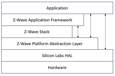
The figure below shows how the application and ZAF interfaces with other elements in Z-Wave.
The figure below shows the architecture of the ZAF.
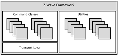
The ZAF consists of three blocks:
Transport Layer: This layer handles all communication with the protocol, which includes single cast, multicast, Multi-Channel encapsulation, delivery of bundled commands, etc.
Command Classes: These modules parse and compose Command Class frames.
Utilities: Utilities are composed of different modules including those that are used for handling I/O communication specific for the WSTK and BRD 8029 boards bundled with the SDK. Other modules are battery monitoring and firmware updating, etc.
The framework implements an event-driven application design.
The framework provides built-in features for developing simpler applications. Transmit buffers are mutex-protected to ensure that the application has only one transmit request job (unsolicited event) at a time. The transmit buffer is released only when the transmit request job is completed or has timed out. The Framework can handle one request job and one response job at the same time.
The ZAF is split into the following two folders:
/CommandClasses/contains CC modules. All CC modules share a protected transmit buffer provided by the ZW_tx_mutex module. The ZW_tx_mutex module implements two transmit buffers, one for request calls and one for response calls./ApplicationUtilities/contains utility modules and interfaces to the transport layer. Some of the modules are used for simple MMI-setup such as button and LED handling. Other modules like association_plus, battery_monitor, battery_plus, and ota_util are more complex utility modules which interface to CC and the client application.
Application Memory Constraints#
The following memory resources are available for certified application development including Z-Wave Framework and Utilities:
64 kB of Flash memory for executable code
8 kB of RAM for temporary data
The above limitations MUST NOT be exceeded. Violating the limitations may impair compatibility with future SDK versions.
The bootloader resides in separate 10 kB storage area and is not part of the certified application.
It is possible to enable a feature that calculates and outputs the code size and non-volatile memory allocation as well as the SRAM memory usage as at the end of the build process.
As a prerequisite, Python 3.x must be installed and available on the system path.
The changes made are only applied on a specific project. If multiple projects exist, then follow the steps for each project.
After creating a project, or already having a project, do the following:
Right-click on the project folder as in the picture, and select Properties.
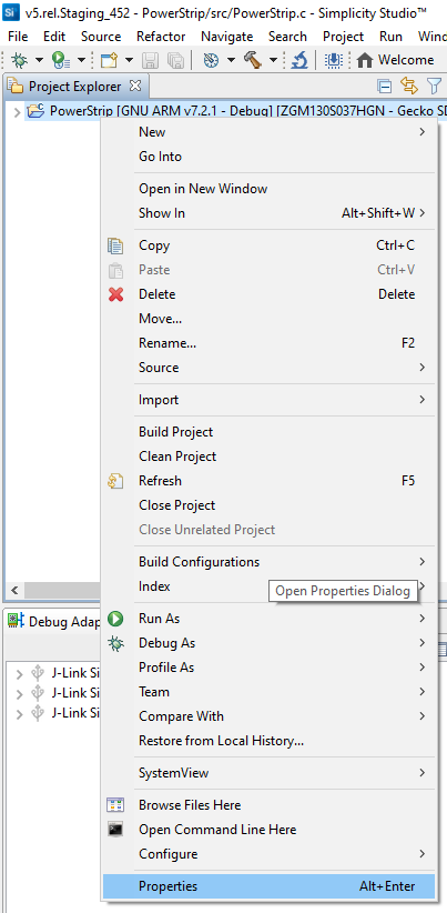
The following dialog box displays:
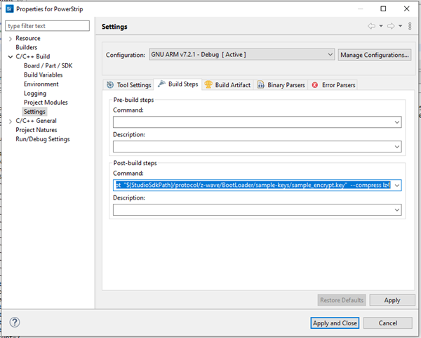
Select C/C++ Build > Settings.
Select the Build Steps tab.
In this tab, you can run commands in a bash environment. As seen above, there are no pre-build commands, but you can use a post-build command for signing the build binary.
Append the following to the end of this already present command.
(remove
old commands)<old_commands> && arm-none-eabi-size -A "${BuildArtifactFileBaseName}.axf" > "${BuildArtifactFileBaseName}_codesize.txt" && python "${StudioSdkPath}/protocol/z-wave/Scripts/size_info_gen.py" -p -i "${BuildArtifactFileBaseName}_codesize.txt"
The full string is 'To enable':
"${CommanderAdapterPackPath}" gbl create "${BuildArtifactFileBaseName}.gbl" --app "${BuildArtifactFileBaseName}.hex" --sign "${StudioSdkPath}/protocol/z-wave/BootLoader/sample-keys/sample_sign.key" --encrypt "${StudioSdkPath}/protocol/z-wave/BootLoader/sample-keys/sample_encrypt.key" --compress lz4 && arm-none-eabi-size -A "${BuildArtifactFileBaseName}.axf" > "${BuildArtifactFileBaseName}_codesize.txt" && python "${StudioSdkPath}/protocol/z-wave/Scripts/size_info_gen.py" -p -i "${BuildArtifactFileBaseName}_codesize.txt"
The full string is 'To disable':
"${CommanderAdapterPackPath}" gbl create "${BuildArtifactFileBaseName}.gbl" --app "${BuildArtifactFileBaseName}.hex" --sign "${StudioSdkPath}/protocol/z-wave/BootLoader/sample-keys/sample_sign.key" --encrypt "${StudioSdkPath}/protocol/z-wave/BootLoader/sample-keys/sample_encrypt.key" --compress lz4
Output:
The demo applications have a corresponding code size information generated for them and these files are available at the following location in the SDK:
C:\SiliconLabs\SimplicityStudio\vX\developer\sdks\gecko_sdk_suite\vX.X\protocol\z-wave\Apps\bin\codesize
The full path may differ on your system and the X’s are version numbers.
Smart Start#
The Smart Start feature is part of the protocol and automatically handles the inclusion process without having a user physically interact with a device. When powered on for the first time, the device tells the world that it is ready for inclusion and most likely a controller nearby will hear this and include the device. If inclusion process times out, it retries again after a given time.
Starting Smart Start Inclusion#
The Smart Start inclusion process starts when the application invokes ZAF_setNetworkLearnMode() with the parameter “E_NETWORK_LEARN_MODE_INCLUSION_SMARTSTART”.
The Z-Wave protocol informs the application about the status of inclusion using the command status handler with the following events:
EZWAVECOMMANDSTATUS_NETWORK_LEARN_MODE_START
EZWAVECOMMANDSTATUS_LEARN_MODE_STATUS
The EZWAVECOMMANDSTATUS_NETWORK_LEARN_MODE_START event contains a status telling whether the inclusion was started successfully.
The EZWAVECOMMANDSTATUS_LEARN_MODE_STATUS event can contain several different statuses:
ELEARNSTATUS_SMART_START_IN_PROGRESS
ELEARNSTATUS_LEARN_IN_PROGRESS
ELEARNSTATUS_LEARN_MODE_COMPLETED_FAILED
ELEARNSTATUS_LEARN_MODE_COMPLETED_TIMEOUT
ELEARNSTATUS_ASSIGN_COMPLETE
The status ELEARNSTATUS_SMART_START_IN_PROGRESS indicates that the process of smart start inclusion to a controller has commenced.
The status ELEARNSTATUS_LEARN_IN_PROGRESS indicates that the process of classic inclusion to a controller has started.
If the status is ELEARNSTATUS_LEARN_MODE_COMPLETED_FAILED, the application must reset its NVM and reboot.
If the status is ELEARNSTATUS_LEARN_MODE_COMPLETED_TIMEOUT, the application must re-enter the Smart Start inclusion process.
Configuring Smart Start Inclusion#
When an end device is in smart start it will send out several inclusion request with increasing delay between. By default, the maximum inclusion request interval is set to 512 seconds.
The maximum inclusion interval can be changed from the application. A higher value might be used in battery powered products to save battery power if it is expected that the product will be in smart start inclusion for a long time. A lower value might be used to ensure a faster smart start inclusion when power consumption is not an issue.
The command for changing the maximum inclusion interval is:
Function:
void ZAF_SetMaxInclusionRequestIntervals(uint32_t intervals) Function for setting the maximum inclusion request delay.
Parameter:
uint32_t intervals Maximum inclusion request delay in 128 seconds steps. Valid range is 5-99
The inclusion requests will be sent out on interval shown in the table below:
Request number | Delay since last inclusion request |
|---|---|
0 (Power up) | 0 sec |
1 | Random(0..16 sec) |
2 | Random(16..32 sec) |
3 | Random(32..64 sec) |
4 | Random(64..128 sec) |
5 | Random(128..256 sec) |
6 | Random(256..512 sec) |
.. | .. |
X | Random(Interval*64..interval*128 sec) |
Power Management#
Power management is handled by the Z-Wave protocol. All listening devices are prevented by the protocol from entering any energy mode other than EM0 and EM1. Listening Sleeping End Devices can enter energy modes EM0-EM2, while non-listening devices can enter the EM0-EM2 modes and the EM4-hibernate mode.
A new module is introduced in the ZAF/ApplicationUtilities called PowerManagement. This module is used to communicate to the protocol if a Listening Sleeping End Device or non-listening application wants to stay awake for a given time. The module makes it possible to register so-called Power Locks that when enabled prevent the processor from going into a low power mode. A power lock can be set to time out after a selectable number of milliseconds or can be enabled indefinitely until cancelled by a new function call. (Indefinite power locks are enabled by setting the timeout value to zero.)
Power Locks are registered in one of two types of configurations described in the table below:
Power Lock Configuration | Description |
|---|---|
PM_TYPE_RADIO | Prevents Listening Sleeping End Devices and non-listening devices from entering other energy modes than EM0 and EM1. This means that the radio transceiver will stay operational. |
PM_TYPE_PERIPHERAL | Prevents non-listening devices from going to deeper sleep than EM2. The radio transceiver is not operational in EM2 but the Low Energy Peripherals are. |
For further details, refer to Power Manager.
True Status Module#
The True Status module implements the requirements for Lifeline Reports as specified in document “Z-Wave Plus v2 Device Type Specification” [15].
The main components of the True Status module are described in the following sub-sections.
True Status Engine (TSE)#
The True Status Engine component is located in the ZAF_ApplicationUtilities_TrueStatusEngine folder and consists of the following source files:
ZAF_TSE.c
ZAF_TSE.h
TSE implements the functionality for registering and handling the state change events that a node wants to report to its lifeline association group members.
A state change can be triggered by a command from a remote note, or by a local change (e.g., a button press).
Public functions:
bool ZAF_TSE_Init();
Function for initializing the True Status Engine. Called by the ZAF during initialization.
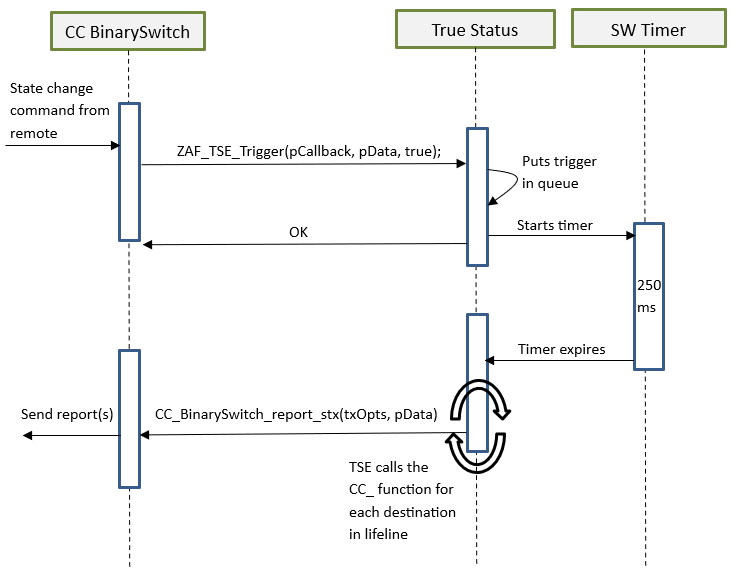
bool ZAF_TSE_Trigger(void* pCallback, void* pData, bool overwrite_previous_trigger);
Function for registering state change events and triggering the report to be sent to lifeline group members after a predefined delay. The delay is currently defined to 250 ms. The delay is a means to prevent network collisions and to avoid generation of redundant reports from rapid state changes.
The function also takes care of sending the report to the relevant lifeline group members only; i.e., it will not send the report to a lifeline destination that issued the command causing the state change. The current implementation can hold up to 3 different state change requests in a queue awaiting the predefined delay to expire. Additional requests during this period will be discarded.
Arguments:
pCallback: Pointer to a callback function for sending the state change report to the lifeline group members. (Described in more details in the next section).
pData: Pointer to a data struct that will be passed in argument to the pCallback function. The pData pointed struct MUST first contain a RECEIVE_OPTIONS_TYPE_EX variable indicating properties about the received frame that triggered the change. Local changes must also include a RECEIVE_OPTIONS_TYPE_EX in the pData struct.
overwrite_previous_trigger: Boolean parameter indicating if a previous trigger with the same pCallback and the same source endpoint in the pData struct should be discarded or not. Set it to true to overwrite previous triggers and false to stack up all the trigger messages.
Returns true if success. False if the request could not be handled (queue is full).
True Status Callback Functions#
The True Status Callback Functions consist of several functions that implement the functionality for sending the actual state change reports to the lifeline association group members. These functions are implemented in each of the relevant command class modules.
The True Status Callback Function is one of the arguments passed to the ZAF_TSE_Trigger() function (described in the previous section), and it will be executed by the True Status Engine for sending the state change reports to each of the relevant members of the lifeline group, one at a time.
An example of a True Status Callback Function implementation can be found in the Command Class BinarySwitch:
void CC_BinarySwitch_report_stx(TRANSMIT_OPTIONS_TYPE_SINGLE_EX txOptions, s_CC_binarySwitch_data_t* pData);
Arguments:
txOptions: Tx Options passed from the True Status Engine with the required destination parameters for sending the state change report to a given lifeline member.
pData: Pointer to the data struct previously registered at the call to ZAF_TSE_Trigger(). Contains the command data for the report to be sent.
It is important to note that a True Status Callback Function must only send the state change reports by single-cast addressing, not by multicast. Therefore, be sure to use only the Transport_SendRequestEP() transmit function for this purpose as it is also done in the CC_BinarySwitch_report_stx() implementation.
True Status Sequence Flows#
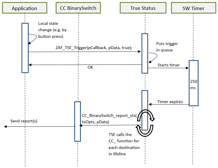
The following diagrams show the function call flows for a BinarySwitch example for the two use cases: (1) state change triggered by a command from a remote note, and (2) state change triggered by a local change (e.g., a button press).
Use Case 1 – State Change Triggered by a Command from a Remote Note#
Use Case 2 – State Change Triggered by a Local Change#