Develop a Power-Optimized BLE Design Featuring PRS, ADC, and LDMA#
Overview#
The EFR32 devices offer a range of low-energy peripherals to help conserve power. By linking peripheral events and moving data autonomously without the CPU, applications can achieve lower power consumption compared to conventional peripheral usage. This lab shows how to set up low-energy peripherals such as the LETimer, PRS, IADC, and LDMA with the Bluetooth stack to create an efficient voltage-sensing device.
Topics covered
Energy Modes
Low-Energy Peripherals
PRS (Peripheral Reflex System)
Energy Modes#
The EFR32 devices support five different energy modes to save power, referred to as Energy Mode 0 (EM0) to Energy Mode 4 (EM4). Depending on the energy mode that the device is in, different peripherals and functionalities are available.
Mode | Description | Lowest Possible Current Consumption (w/no peripherals) |
|---|---|---|
EM0 | Active | 22.0 uA/MHz |
EM1 | Sleep | 13.0 uA/MHz |
EM2 | Deep Sleep | 1.03 uA |
EM3 | Stop | 1.05 uA |
EM4 | Shut Off | 0.17 uA |
These values are referenced from the EFR32BG22 Wireless Gecko SoC Family Data Sheet and could be higher based on different operating conditions. For more detailed information, see the respective EFR32 data sheet.
Program execution for the EFR32BG22 can only occur in EM0 - Active Mode. The CPU is active and all clocked-peripherals are operational in EM0. Whenever the CPU does not have to execute, the device can enter different energy modes to save power. Current consumption decreases because the number of clocks and peripherals that are still operational decreases.
The following table shows how to transition between energy modes. For this lab, the device will wake from EM2 to EM1 from a peripheral event to transfer data. After data is transferred, the device automatically goes back to EM1. An interrupt will wake the device to EM0 to execute the CPU. The WFI (Wait for Interrupt) or WFE (Wait for Event) ARM instructions are executed to make the device go into EM2.
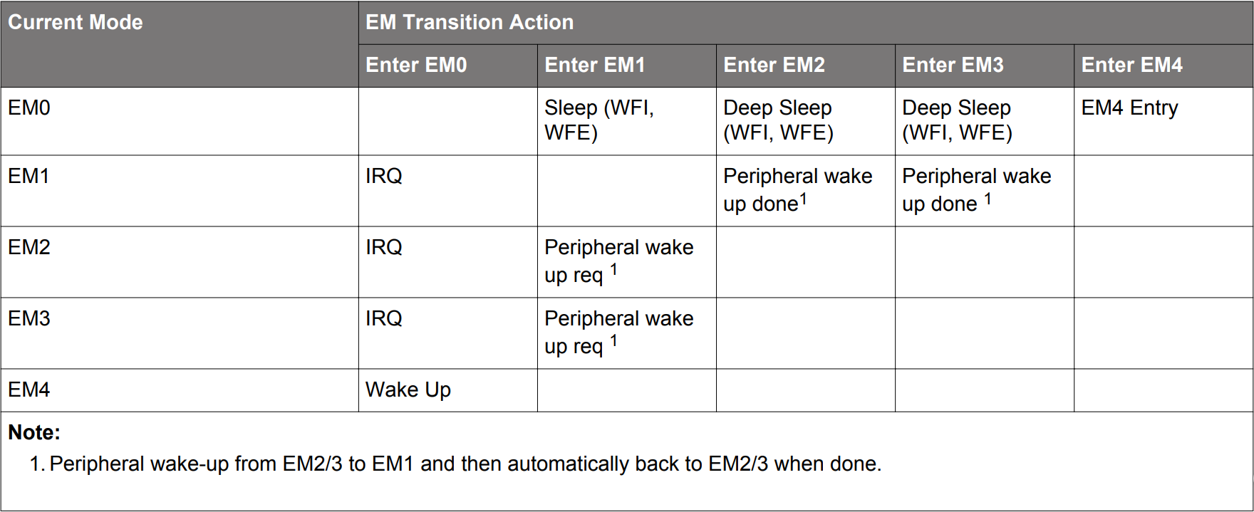

For detailed information about energy modes, see the EFR32xG22 Wireless Gecko Reference Manual Section 12.
Low-Energy Peripherals#
The EFR32 devices offer many low-energy peripherals that can operate in different energy modes.
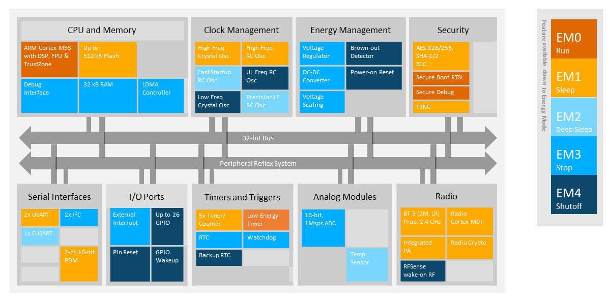

For detailed information about clocks and the available peripherals in different energy modes, see EFR32xG22 Wireless Gecko Reference Manual table 12.2.
Each peripheral runs on a particular clock, which determines the energy mode(s) the peripheral can operate in. For the diagrams of the Bus Clocks, which map the peripherals to their respective clocks, see the EFR32xG22 Wireless Gecko Reference Manual section 8.3.
This lab uses the LETIMER and IADC peripherals. LETIMER runs on the EM23GRPACLK (Energy Mode 2 and 3 Group A Clock) branch. The IADC runs on the IADCCLK (IADC Clock) branch. To run IADC while the device is sleeping, the IADCCLK must use the FSRCO (Fast Startup RC Oscillator) to get to the same energy mode as the LETIMER.
Additionally, the Linked DMA is used to automatically transfer data from the IADC peripheral register to a memory buffer. By bypassing the CPU to transfer data, the LDMA saves a significant amount of energy. After a certain number of data samples have been transferred and recorded, the LDMA interrupt wakes up the device to process the data samples.
The block diagram in Signal Flow shows the interconnections between peripherals.
Peripheral Reflex System#
The Peripheral Reflex System (PRS) allows for configurable, fast, and autonomous communication between these low-energy peripherals. Depending on the user's application, different events from one peripheral can trigger different actions of another peripheral. By using the PRS, the device can bypass the CPU to trigger peripheral operations and, as a result, save power.
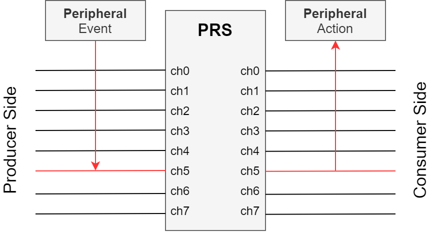

This lab uses the PRS to trigger an IADC conversion when the LETIMER times out. However, with the flexibility of the PRS, other peripheral events, such as a GPIO pin toggle or a UART receive operation, can trigger the IADC instead. PRS can also use a logical combination of multiple events to define the trigger for the action.
For more information about the PRS, see the EFR32xG22 Wireless Gecko Reference Manual section 13 and AN0025: Peripheral Reflex System (PRS).
Signal Flow#
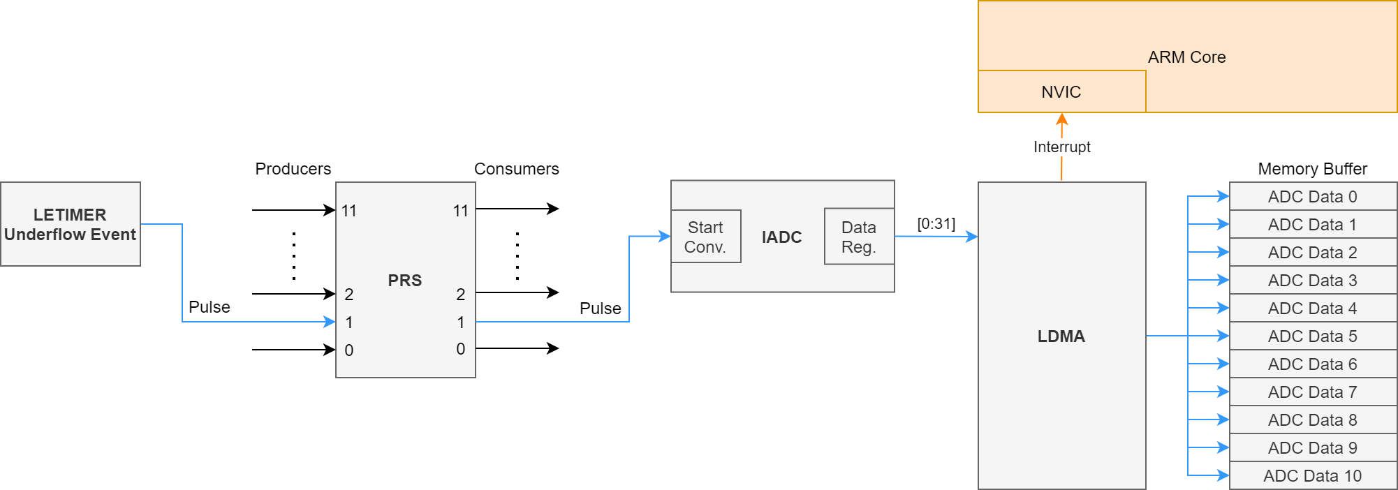
The EFR32 devices are capable of autonomous hardware operations in low-power mode. Multiple peripheral events can be processed and triggered and data can be transferred in RAM without the CPU.
To save energy while periodically measuring the voltage, the device example for this lab will be using the following peripherals:
LETIMER0
PRS
IADC
LDMA
The LETIMER will periodically trigger the IADC to start a conversion through the PRS. After the IADC conversion is complete, the LDMA will transfer the raw ADC data into a buffer. After all samples have been measured, the device will notify all connected devices of the new average voltage through Bluetooth Low Energy.

Bluetooth Low Energy#
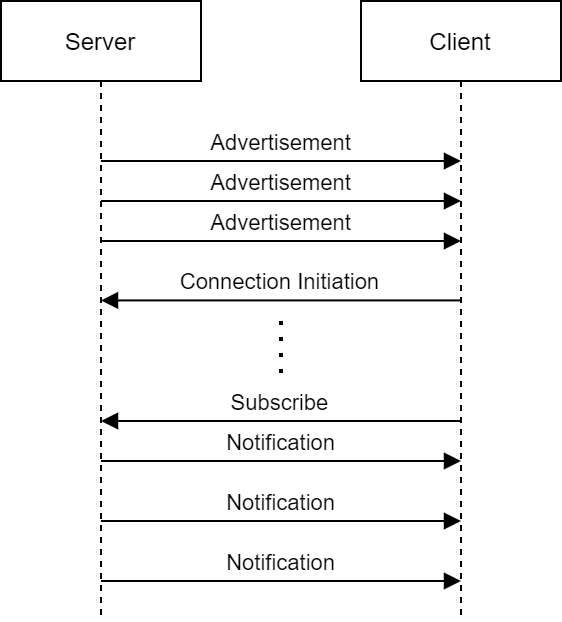
The Bluetooth stack can operate all the way down to EM2. This lab will set up a Bluetooth server to send the analog data to a Bluetooth client. The EFR32 device will send notifications to the connected smartphone of new analog data.

Lab#
Creating the Project#
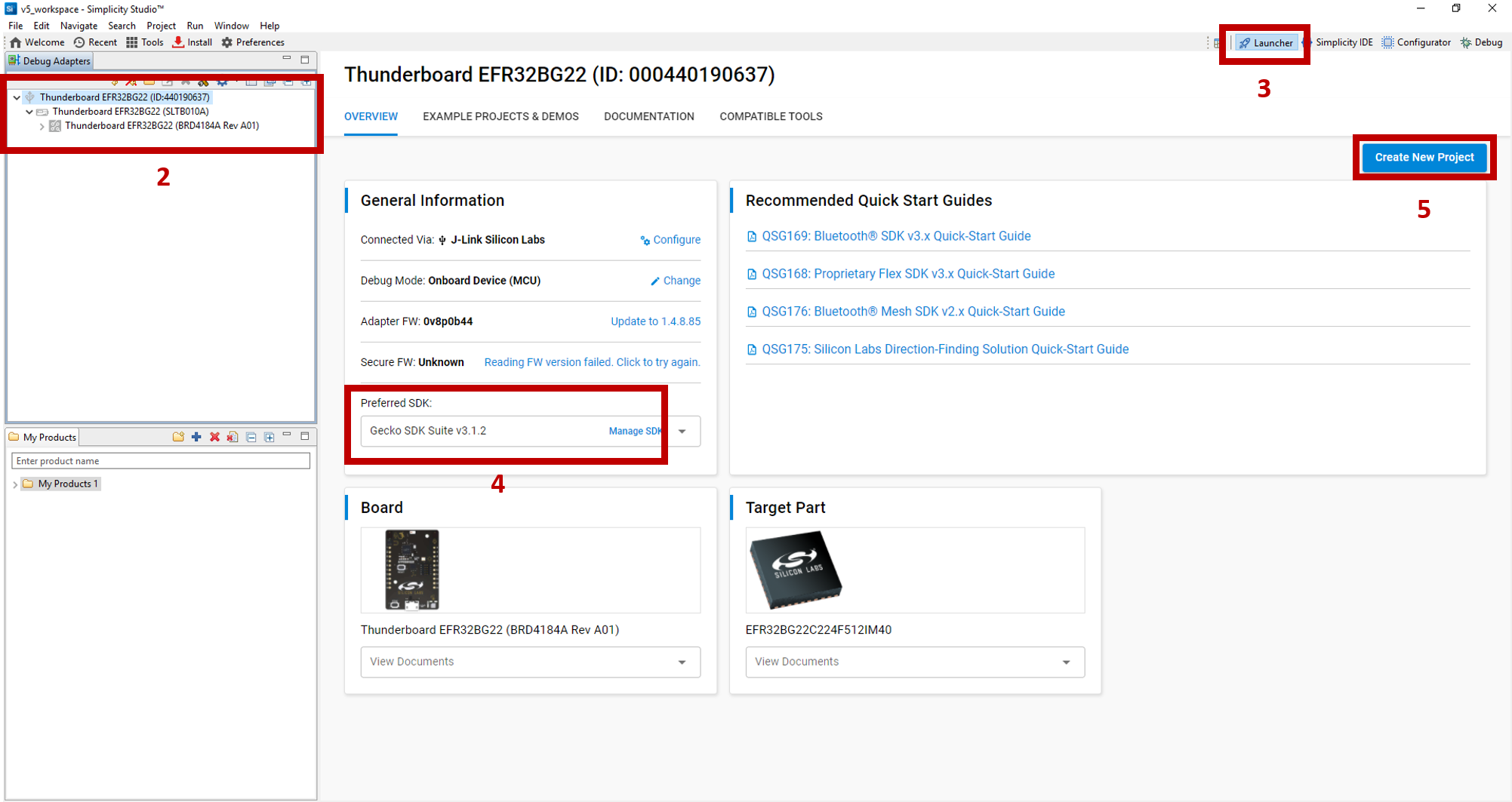
If the BG22 WSTK has not been plugged in using the USB cable, do so now. The kit and debug information should be displayed in the Debug Adapters window.
In the
Debug Adapterswindow, click on the device.Information about the target hardware and software will appear. If this does not appear, click on the
Launcherbutton in the top right corner.Select the
Preferred SDKto the latest version. For this lab, the latest version of Gecko SDK (v3.1.2) is used.Click on
Create New Projectin the upper right hand corner. A "New Project Wizard" window should appear.

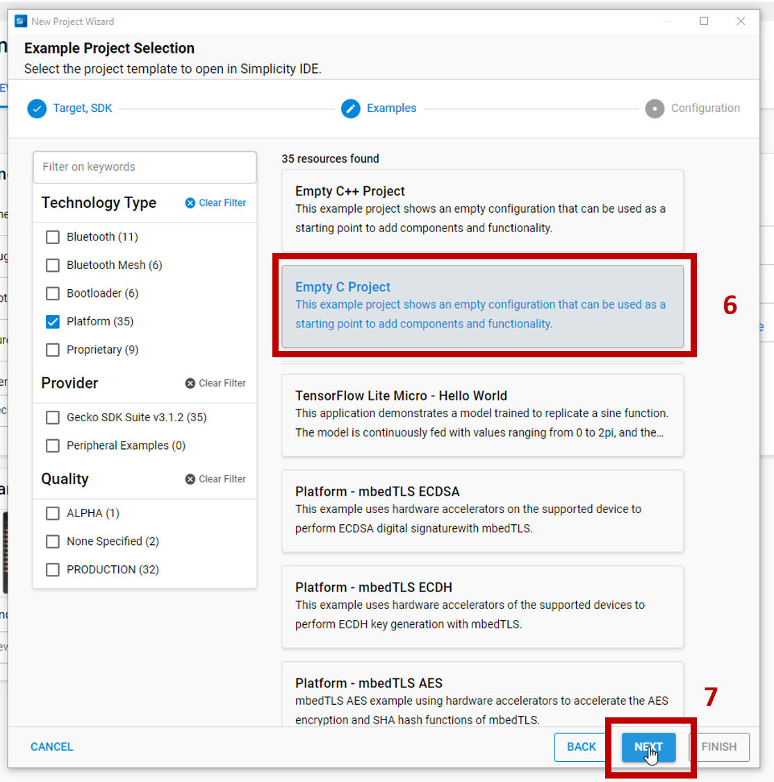
For this lab, the Bluetooth - SoC Empty project will be used as the starter project. Scroll and select Bluetooth - SoC Empty. Note: to filter the projects, click on Bluetooth for the Technology Type.
Click
Nextto move on.

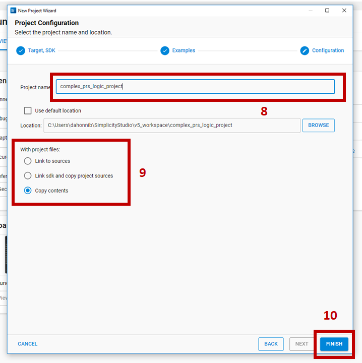
Rename the project. For this lab, name the project
soc_le_voltage_monitor.Select
Copy contentsto copy the project files into your project. This makes version control easier to manage and future updates to the Simplicity Studio libraries will not impact the copied files in this project.Click
Finishto generate the project.

Installing the EMLIB components#
Previously in SSv4, the desired EMLIB source files had to be manually copied to a project. Now in SSv5, the configurator can be used to install the source files. Open the
soc_le_voltage_monitor.sclpfile. The file will show information about the target hardware and software.
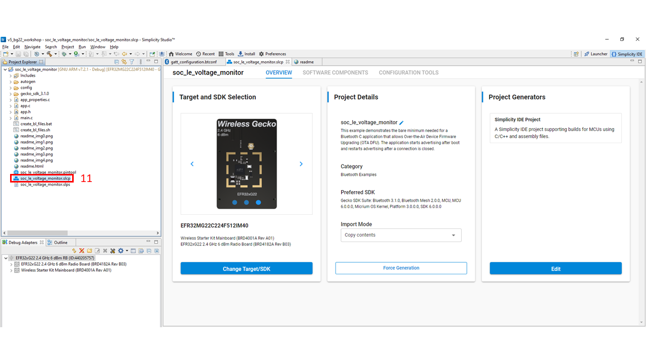

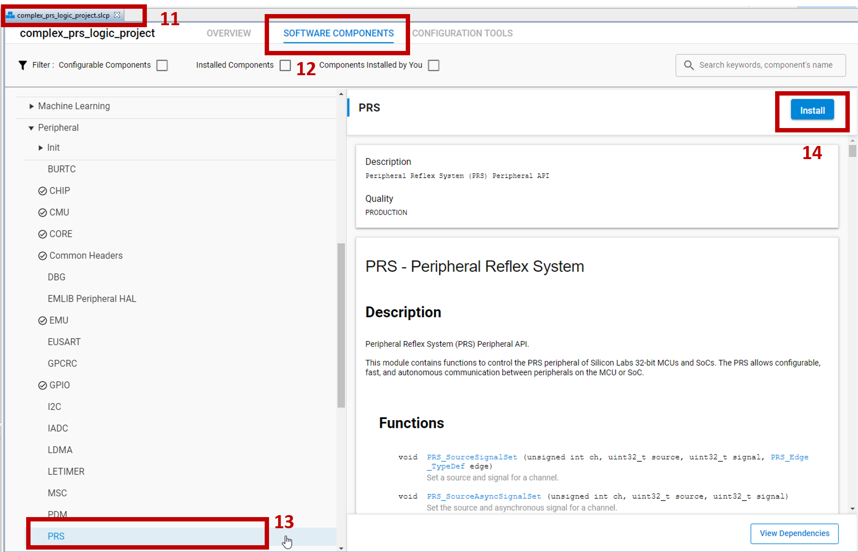
Select the
Software Componentstab at the top.Scroll down to the "Platform" section. Notice how there are many components available that you can install for your application with ease.

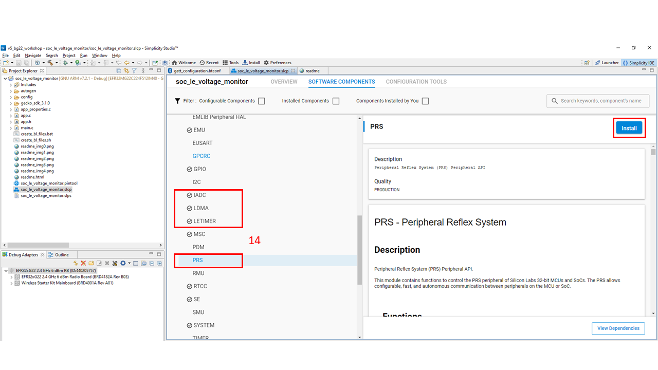
The list of EMLIB source files is available under "Peripherals". Install the following components using the
Installbutton as shown in the image. The process is repeated for all 4 components.IADC
LDMA
LETIMER
PRS

Adding a Custom BLE GATT Service and Characteristic#
The average data that the IADC sampled can be retrieved wirelessly through BLE. To make the data visible, a custom GATT service and characteristic are used.
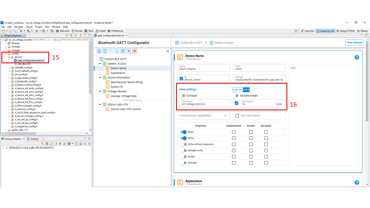
Open the GATT configurator, which is located in ./config/btconf/gatt_configuration.btconf. The GATT configurator GUI has been updated and is very different compared to SSv4.
For this lab, the
Device namewill be modified to "LE Voltage Monitor" located under the Generic Access characteristics. TheValue lengthwill have to be updated to 18.

Click on the left-most icon in the top left corner of the GATT configurator and select
New Service.Click on the new custom service and rename the service to "Voltage Monitor".
Add an ID to the custom service to give a meaningful ID reference to the service. For this lab, "voltage_monitor" is used for the ID.
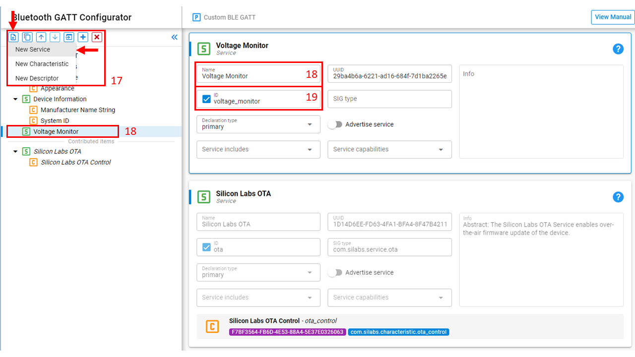

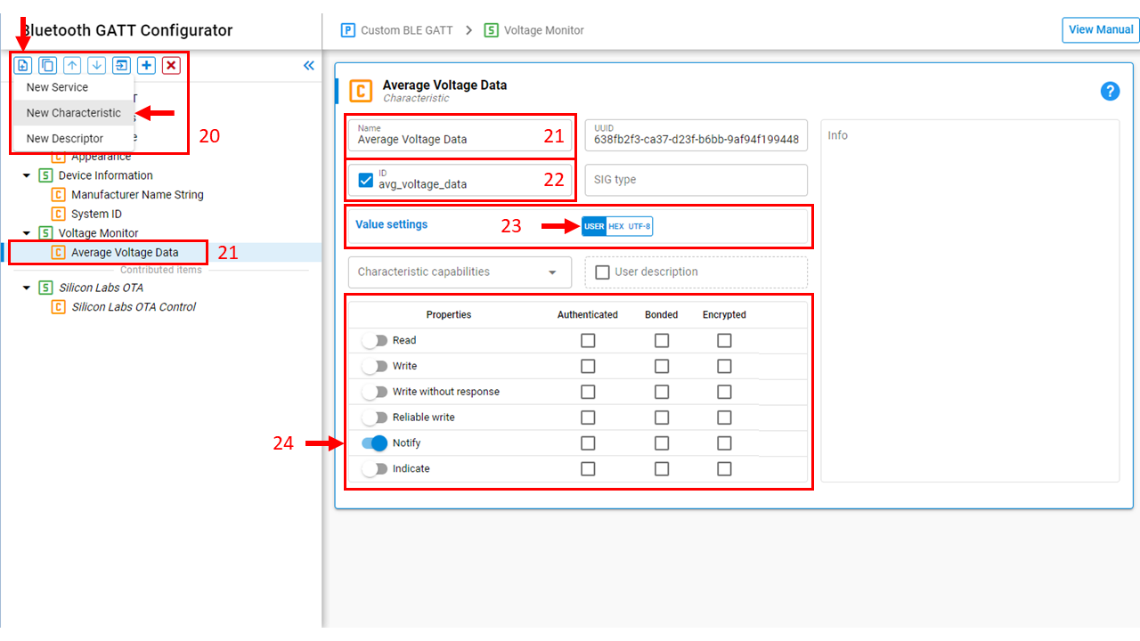
Click on the left-most icon in the top left corner of the GATT configurator and select
New Characteristic.Click on the new custom characteristic. For this lab, rename the characteristic to be "Average Voltage Data".
Add an ID to the custom characteristic. For this lab, "avg_voltage_data" is used for the ID. This ID field will create a meaningful name for the GATT characteristic variable to use in code development. This variable can be found in gatt_db.h and the variable will be prefixed with gattdb.
Select
USERfor theValue settings. This will require the user to allocate their own resources for the GATT characteristic. For more information, see KBA.Select
NotifyunderProperties. The EFR32 device will notify connected devices of any GATT characteristic value changes.

Adding the Project Source Files#
Copy le_voltage_monitor.c source files to the top level of the project. The source files and code details are found at the Code Explanation section of this doc. App.c will overwrite the existing file to add the new application. The source files can be dragged and dropped into Simplicity Studio or placed in this file path:
./Users/JohnDoe/SimplicityStudio/v5_workspace/soc_le_voltage_monitorBuild and Flash the Project#
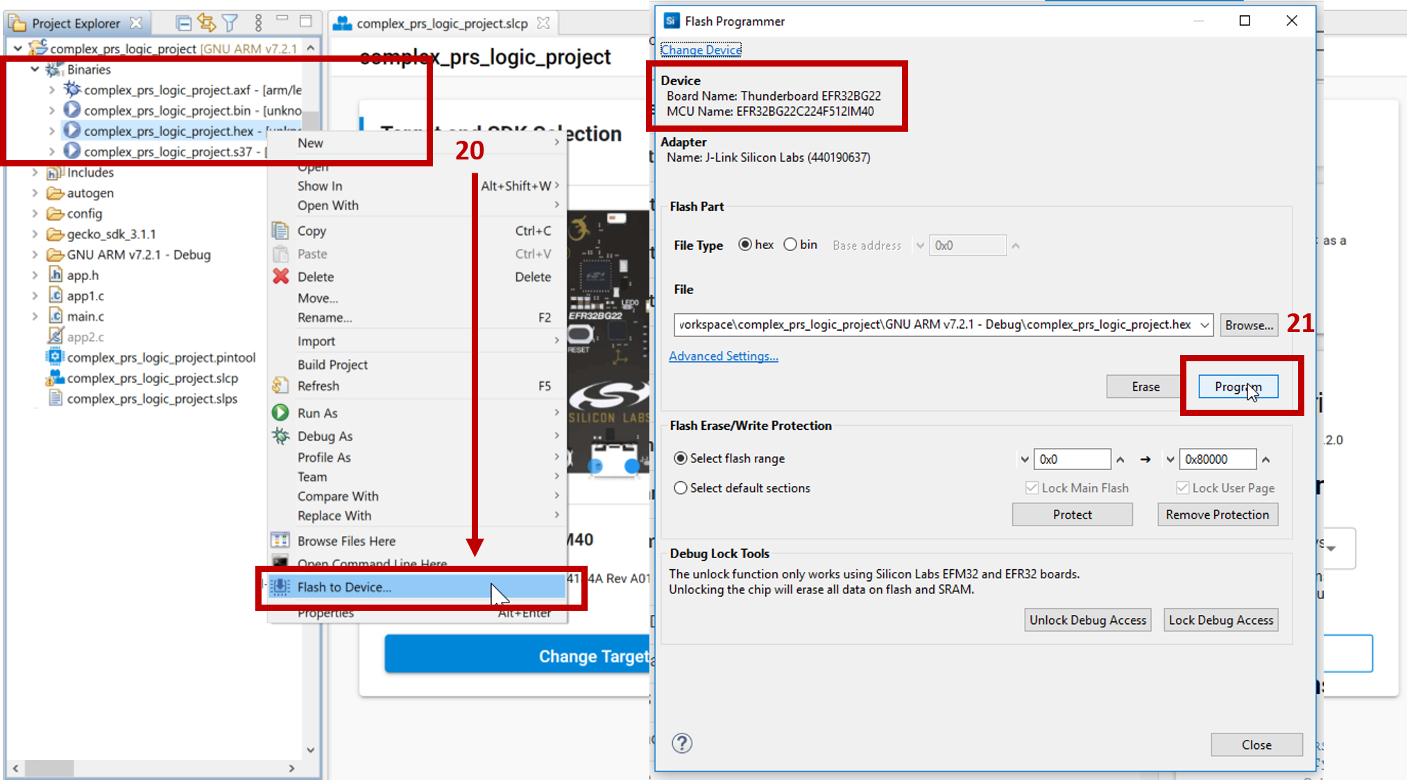
Build the project by clicking on the hammer icon in the top left corner of the Simplicity Studio IDE.
Right-click on the hex file and select
Flash to Device...to make the Flash Programmer window appear. Note: if a Device Selection window appears, select the correct device.Click
Programto flash the device.

Usage#
Connecting with EFR Connect App#
With the EFR Connect App, connect to the device and view the average voltage data that is sent from the EFR32BG22 device.
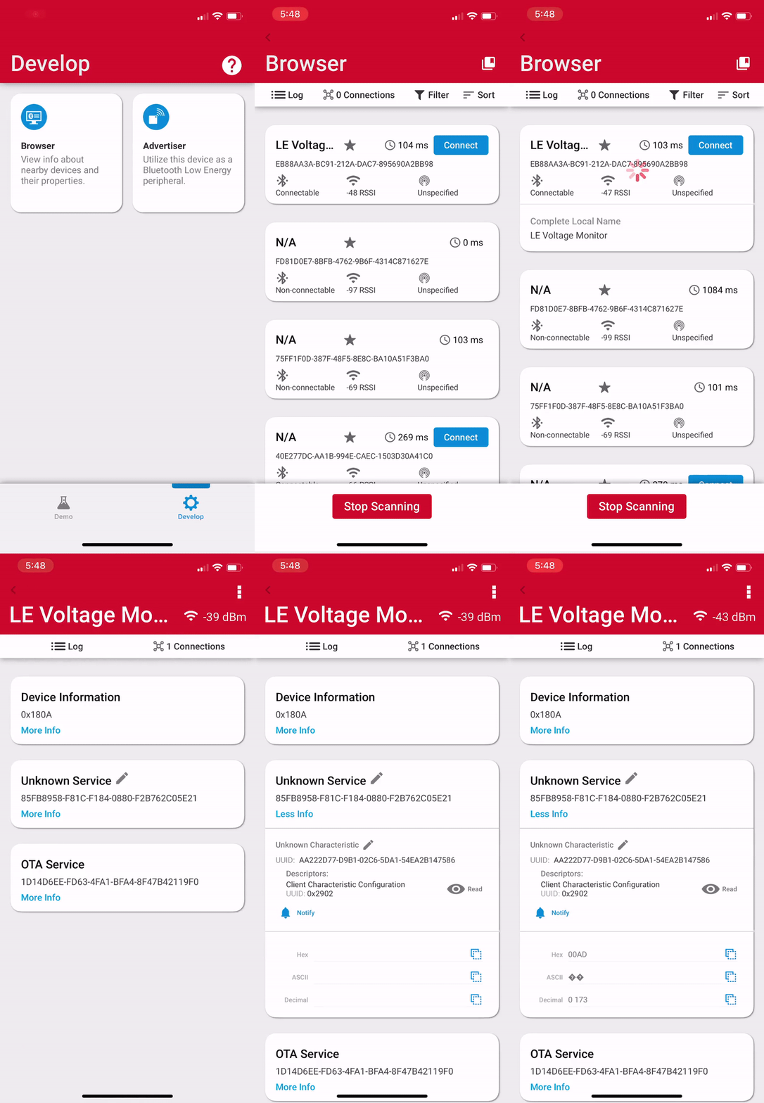

NOTE: If the EFR32 is not advertising, the bootloader may not be loaded. Create and flash the "Internal Storage Bootloader" project.
Viewing the Energy Profiler (OPTIONAL)#
To monitor the current draw of the Thunderboard BG22, a WSTK development board is needed because the AEM (Advanced Energy Metering) hardware is not present on the Thunderboard. Using the Mini Simplicity Connector, connect the WSTK to the Thunderboard, as shown in the image. For more information on the connection, see AN958: Debugging and Programming Interfaces for Custom Designs.
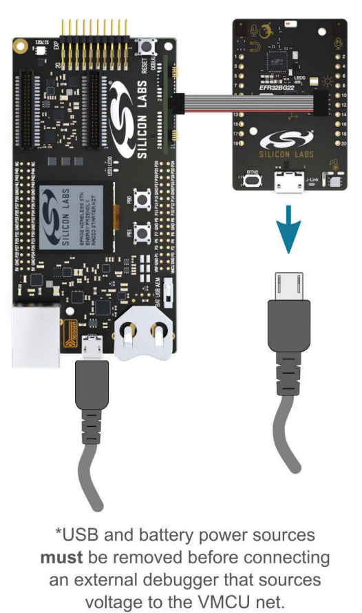

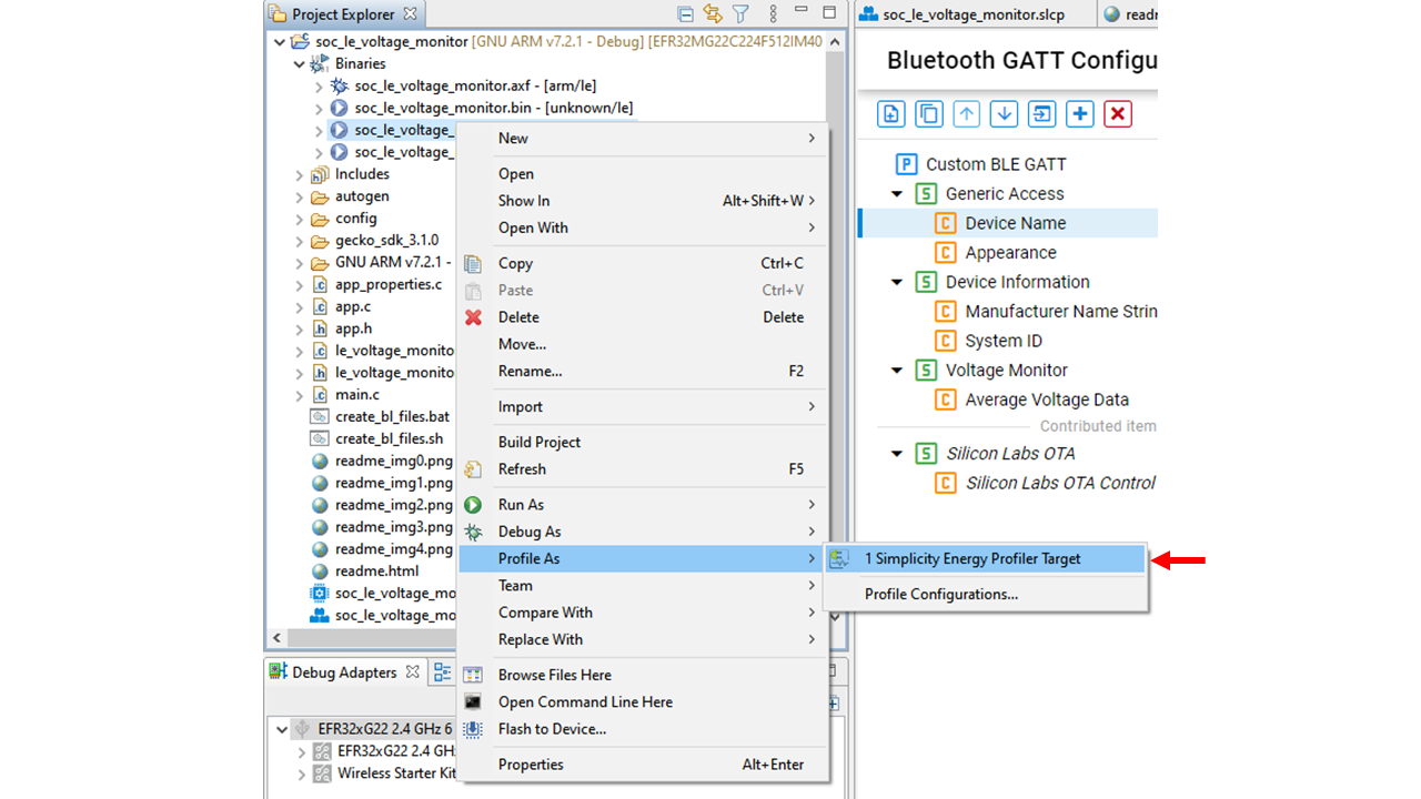
This KBA shows steps on how to connect the debugger to the Thunderboard with Simplicity Studio. After the setup, right-click on the hex file and click "Profile As" to show an option to run the "Simplicity Energy Profiler Target", as shown below.

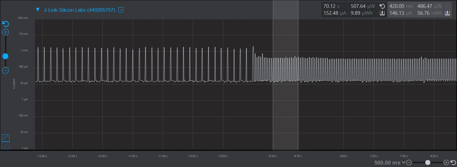
With the Energy Profiler, the current consumption of the device can be monitored.

Code Explanation#
The following sections explain critical lines of code pertinent to this lab. The code can be found here:
Application#
The SoC-Empty project generates a default app.c source file with a skeleton Bluetooth event handler. The app.c file provided for this lab adds code to handle the BLE connection and notifications.
The voltage monitor is initialized in app_init() in line 35 of app.c. The voltage monitor IADC does not start sampling until a connection has been made and the user has enabled GATT notifications to the Average Volage Data characteristic.
Connection Opened#
When a connection is opened, the sl_bt_evt_connection_opened_id event is called in line 122 of app.c. In this event, the connection handle is saved to use for notifications.
// This event indicates that a new connection was opened.
case sl_bt_evt_connection_opened_id:
    connection_handle = evt->data.evt_connection_opened.connection;
    break;
Notifications Enabled#
After the user has enabled GATT notifications to the characteristic, the sl_bt_evt_gatt_server_characteristic_status_id event is triggered. In this event, the voltage sampling will begin and the device will periodically update the average voltage data characteristic value until the device disconnects. This event is located in line 147 of app.c.
case sl_bt_evt_gatt_server_characteristic_status_id:
    // Check if Average Voltage Characteristic changed
    if(evt->data.evt_gatt_server_characteristic_status.characteristic == gattdb_avg_voltage_data) {

        // client characteristic configuration changed by remote GATT client
        if(gatt_server_client_config == (gatt_server_characteristic_status_flag_t)evt->data.evt_gatt_server_characteristic_status.status_flags) {

            // Check if EFR Connect App enabled notifications
            if(gatt_disable != evt->data.evt_gatt_server_characteristic_status.client_config_flags) {
                // Start sampling data
                le_voltage_monitor_start_next();
            }
            // indication and notifications disabled
            else {
                le_voltage_monitor_stop();
            }
        }
    }
    break;
LDMA Trigger#
When the monitor completes sampling, the LDMA interrupt triggers the sl_bt_evt_system_external_signal_id event. This event is located in line 161 of app.c. More details are provided in the LDMA Interrupt section. This event will be triggered periodically once the GATT notification is enabled. The event calculates the average voltage data from the samples recorded, converts the endianness to display a readable value on the EFR Connect App, and then sends the value to the smartphone or connected device.
case sl_bt_evt_system_external_signal_id:

    // External signal triggered from LDMA interrupt
    if(evt->data.evt_system_external_signal.extsignals & LE_MONITOR_SIGNAL) {
        // Get the average
        uint16_t data_mV = le_voltage_monitor_get_average_mv();

        // Convert endianess
        volt_buf[0] = (data_mV >> 8) & 0x00FF;
        volt_buf[1] = data_mV & 0x00FF;

        // Notify connected user
        sc = sl_bt_gatt_server_send_notification(connection_handle,
                                                 gattdb_avg_voltage_data,
                                                 sizeof(volt_buf),
                                                 (uint8_t *)&volt_buf);
        sl_app_assert(sc == SL_STATUS_OK,
                      "[E: 0x%04x] Failed to send characteristic notification\n",
                      (int)sc);

        // Start the next measurements
        le_voltage_monitor_start_next();
    }
    break;
Connection Closed#
When the connection is closed, the sl_bt_evt_connection_closed_id event is triggered in line 128 of app.c. The voltage monitor stops to save power when no devices are connected with the le_voltage_monitor_stop() function.
// This event indicates that a connection was closed.
case sl_bt_evt_connection_closed_id:
    le_voltage_monitor_stop();

    // Restart advertising after client has disconnected.
    sc = sl_bt_advertiser_start(
        advertising_set_handle,
        advertiser_general_discoverable,
        advertiser_connectable_scannable);
    sl_app_assert(sc == SL_STATUS_OK,
                  "[E: 0x%04x] Failed to start advertising\n",
                  (int)sc);

    break;
Clocks Initialization#
The init_clocks() static function in line 214 of le_voltage_monitor.c enables and configures all the clocks for the peripherals in this lab. To operate in EM2, the LETIMER0 and IADC0 clocks need special configuration.
The clock for LETIMER0 is connected to the EM23GPACLK branch, which has the option to run off of one of three low-frequency oscillators. The CMU_ClockSelectSet( ) function is used to select a particular low-frequency oscillator. For this lab, the LFXO (Low Frequency Crystal Oscillator) is selected because of its accuracy.
// Select LETimer0 clock to run off LFXO
// Reference: EFR32xG22 RM, Figure 8.3
CMU_ClockSelectSet(cmuClock_EM23GRPACLK, cmuSelect_LFXO);

// Enable LETimer0 clock
CMU_ClockEnable(cmuClock_LETIMER0, true);
The clock for IADC0 is connected to the IADCCLK branch, which has the option to run off of the EM01GRPACLK branch or the FSRCO (Fast Startup RC Oscillator). To get the IADC running in EM2, use the FSRCO.
// Configure IADC clock source for use while in EM2
// Reference: EFR32xG22 RM, Figure 8.2
CMU_ClockSelectSet(cmuClock_IADCCLK, cmuSelect_FSRCO);  // FSRCO - 20MHz

// Enable IADC0 clock
CMU_ClockEnable(cmuClock_IADC0, true);
LETIMER Initialization#
The init_letimer() static function in line 247 of le_voltage_monitor.c initializes the LETimer.
The LETIMER0's timeout frequency determines the sampling frequency, which can be modified with the #define SAMPLING_FREQ_HZ macro definition in le_voltage_monitor.h. For this lab, the LETIMER should constantly be running when sampling. The .repMode field of the init struct will configure the LETIMER to repeat continuously. On a timer underflow event, the LETIMER needs to send a pulse signal to the IADC through PRS, which can be configured with the .ufao0 field of the init struct. The PRS channel configuration will be covered in the PRS Initialization section.
// Line 184
// Initialize letimer to run in free running mode
// Reference: EFR32xG22 RM, Section 18.3.2
init.repMode = letimerRepeatFree;

// Pulse output for PRS
init.ufoa0 = letimerUFOAPulse;

// Set frequency
init.topValue = CMU_ClockFreqGet(cmuClock_LETIMER0) / LETIMER_FREQ;
IADC Initialization#
The init_iadc() static function in line 292 of le_voltage_monitor.c initializes the IADC.
Before connecting the PRS output channel to the IADC start conversion trigger, the IADC must correctly select the trigger source and action.
// On every trigger, start conversion
initSingle.triggerAction = iadcTriggerActionOnce;

// Set conversions to trigger from LETIMER/PRS
initSingle.triggerSelect = iadcTriggerSelPrs0PosEdge;
The .triggerAction field of the init struct will determine the number of samples from a single ADC conversion. For this lab, every timeout of the LETIMER will only sample one ADC measurement per trigger. The .triggerSelect field will configure the ADC to trigger on a PRS positive edge signal.
Note: Prs0 does not mean channel 0. The PRS channel configuration is covered in the PRS Initialization section.
The .posInput and .negInput can be modified to change the IADC pins. The IADC_INPUT_POS and IADC_INPUT_NEG macro definitions are defined at the top of le_voltage_monitor.c. These are currently defined to use PA8 and GND, respectively. Depending on the GPIO ports that are used for the IADC pins, #define IADC_INPUT_BUSALLOC macro definition must also be modified to the correct analog bus. For more information about the analog bus, see the EFR32xG22 Wireless Gecko Reference Manual section 25.3.12.2.
// Configure Input sources for single ended conversion
initSingleInput.posInput = IADC_INPUT_POS;
initSingleInput.negInput = IADC_INPUT_NEG;

// Allocate the analog bus for IADC0 input
GPIO->IADC_INPUT_BUS |= IADC_INPUT_BUSALLOC;
After the IADC conversion is complete, the IADC must wake the LDMA to transfer the raw data from the IADC data register to a memory buffer. The .fifoDmaWakeup field of the init struct will enable the IADC to wake the LDMA when the internal IADC FIFO is filled to a certain level. The .dataValidLevel field of the init struct sets the threshold level to wake the LDMA. For this lab, the LDMA will be triggered when one sample point is pushed into the FIFO.
// Wake up the DMA when FIFO is filled
initSingle.fifoDmaWakeup = true;

// Set how many elements in FIFO will generate DMA request
initSingle.dataValidLevel = iadcFifoCfgDvl1;
PRS Initialization#
The init_prs() static function in line 274 of le_voltage_monitor.c configures the the Producer and Consumer side of the PRS peripheral. For this lab, the PRS_SourceAsyncSignalSet( ) function connects channel 1 of the producer-side of the PRS to the LETIMER underflow event. The PRS_ConnectConsumer( ) function connects channel 1 of the consumer-side of the PRS to the IADC start conversion trigger. To use a different PRS channel, change the PRS_CHANNEL_LETIMER_IADC macro definition, which is defined at the top. The PRS_ASYNC_CH_CTRL_x macro definitions are defined the em_prs.h EMLIB library.
// Producer
PRS_SourceAsyncSignalSet(PRS_CHANNEL_LETIMER_IADC,
                        PRS_ASYNC_CH_CTRL_SOURCESEL_LETIMER0,
                        PRS_ASYNC_CH_CTRL_SIGSEL_LETIMER0CH0);

// Consumer
PRS_ConnectConsumer(PRS_CHANNEL_LETIMER_IADC,
                    prsTypeAsync,
                    prsConsumerIADC0_SINGLETRIGGER);
LDMA Initialization#
The init_ldma() static function in line 355 of le_voltage_monitor.c initializes the LDMA.
With the simplicity of EMLIB, the initialization of the LDMA is mainly focused on setting up the LDMA transfer configuration and descriptor. The LDMA is transferring data from a peripheral register to a memory buffer. The transfer configuration and descriptor are allocated as the following for this lab:
// Configure LDMA to trigger from IADC peripheral
static LDMA_TransferCfg_t xferCfg = LDMA_TRANSFER_CFG_PERIPHERAL(ldmaPeripheralSignal_IADC0_IADC_SINGLE);

static LDMA_Descriptor_t descriptor = LDMA_DESCRIPTOR_LINKREL_P2M_WORD(&(IADC0->SINGLEFIFODATA), // src
                                                                        samplingBuffer,            // dest
                                                                        NUM_OF_SAMPLES,      // number of samples to transfer
                                                                        1);
LDMA Interrupt#
The LDMA interrupt handler is located in line 379 of le_voltage_monitor.c.
When the memory buffer is filled, the LDMA interrupt is triggered. The interrupt will wake the device from EM2. The LDMA interrupt handler acknowledges the interrupt flag and sets a flag for the foreground thread to process and notify any connected devices. The sl_bt_external_signal( ) function will generate a Bluetooth stack event for the main loop to handle and keep the interrupt short.
For more information on handling interrupts with the Bluetooth stack, see UG434: Silicon Labs Bluetooth ® C Application Developer's Guide for SDK v3.x section 6.1.
