Bluetooth TX Power Settings#
Introduction#
The default TX power used by the Bluetooth stack is +8 dBm, meaning that all of the advertisement packets and data packets are transmitted with this power level (except if your device has a lower TX power capability). However, this can be changed both in positive and negative direction. The actual TX power is determined by both the user configuration and the actual circumstances. This document discusses how you can configure TX power and how the actual TX power will change.
Global Maximum and Minimum TX Power#
The global maximum TX power can be set with the sl_bt_system_set_tx_power(int16_t min_power, int16_t max_power, int16_t * set_min, int16_t * set_max ) API command. The unit of the TX power is 0.1 dBm. To ensure safe functioning, suspend radio operations for a short time while changing the TX power. For example, to set 2.3 dBm maximum TX power and 0 dBm minimum TX power, use the following commands:
sl_bt_system_halt(1);
gecko_cmd_system_set_tx_power(0, 23, &set_min, &set_max);
sl_bt_system_halt(0);
Note that, although you can set the TX power with 0.1 dBm granularity, the low power PA cannot be set to arbitrary TX levels – there are discrete power levels you can use. The set values are provided by the variables pointed to, by their arguments set_min and set_max. Always check these values because it can be much higher/lower than the TX power you want to set.
The minimum TX power setting has no effect in Bluetooth stack if the LE Power Control (LEPC) is not enabled. LEPC is a new feature introduced in BLE 5.2, which can be used to adjust a connected peer device’s transmit power level based on the received signal strength. The feature is used only in connections and does not affect advertisements. To enable LECP, install the Power Control software component in your project.
However, the application may still use the set_min setting for other purposes than LEPC, e.g., setting the minimum TX power for DTM transmitter test.”
On the other hand, by default, all radio operations use the global maximum TX power provided there are no other constraints. The possible constraints are discussed in the following sections.
TX Power for Data Packets#
Although the Bluetooth standard does not limit TX power, local regulatory bodies (CE, FCC, and so on) can define the maximum TX power that can be used (see: TX Power Limitations for Regulatory Compliance). Different rules apply for different regions. ETSI (European Telecommunications Standards Institute) has the strictest rules regarding the TX power. Therefore, to comply with regulations in all regions, ETSI regulations have to be taken into account.
According to ETSI, the maximum allowed TX power on a Bluetooth connection is +20 dBm if Adaptive Frequency Hopping (AFH) is enabled, and +10 dBm if AFH is not enabled or if AFH is enabled but less than 15 channels are available for use.
AFH can be enabled by installing the AFH software component in your project. For more information, see Adaptive Frequency Hopping. If AFH is enabled, the Bluetooth stack automatically controls the TX power. If 15 or more channels are available, TX power of data packets is set to the global maximum, which cannot be more than +20 dBm. If less than 15 channels are available, TX power is set to the minimum of the global maximum TX power and +10 dBm. If AFH is disabled, TX power is set to the minimum of the global maximum TX power and +10 dBm.
RF Path Compensation#
The TX power set in the stack is the output power of the Power Amplifier (PA). However, your signal may suffer some loss along the RF path, meaning that the actually radiated power is less than the power you set.
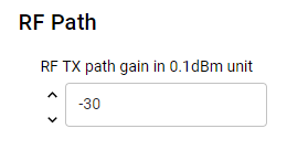
Beginning with Bluetooth SDK v2.9, the stack automatically controls the TX power according to the AFH settings. Consequently, it needs to know how much loss your RF path introduces. The RF path loss can be set in the configuration of the Bluetooth Core software component with 0.1 dBm granularity. For example, if you have a 3 dB loss, set the following in the configuration.


The negative number means loss and positive number means gain. If you set +5 dBm with sl_bt_system_set_tx_power, it is +8 dBm on the output of the PA and +5 dBm radiated power.
RF path compensation can be set for the receive path as well (see RF RX path gain). In this case, the reported RSSI value will be compensated with this value.
TX Power for Advertisement Packets#
Bluetooth advertisements use three advertisement channels. As a result, even if AFH is enabled, the maximum TX power for advertisements is +10 dBm. If you set the global maximum higher than this, advertisements will be transmitted with +10 dBm.
Extended advertisements use data channels, hence the extended advertisement packets can be transmitted with +20 dBm if AFH is enabled and 15 or more data channels are available.
Since Bluetooth SDK v2.9, you can set different TX power levels for different advertisers. Use the following API command to set the TX power for a specific advertiser (identified by an advertiser handle) in SDK v3.x:
sl_bt_advertiser_set_tx_power(uint8_t handle, uint16_t tx_power, uint16_t* set_power)Note however, that you still cannot go beyond the global maximum TX power, i.e., if you set a TX power higher than the global maximum, the global maximum will be applied (or +10 dBm if global TX power is higher than that). If you don't define TX power for an advertiser, it will automatically use the global maximum (or +10 dBm if global TX power is higher than that). If the advertiser is currently active, the TX power for the advertiser will change only after re-enabling it.
Supplying EFR32 PAVDD from 3.3 V#
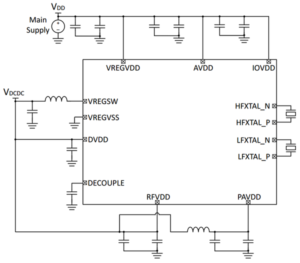
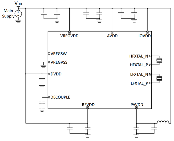
On EFR32 SoC based designs, you can supply the Power Amplifier voltage regulator VDD input (PAVDD) from the output of the DC/DC or straight from a 3.3 V power supply. It is important for the Bluetooth stack to know which voltage is applied on PAVDD to set the appropriate TX level.
Sample apps are configured to work well on Silicon Labs radio boards (PAVDD input is always selected based on the board type). On custom config, however, you have to define if PAVDD is driven from 3.3 V (VBAT) or 1.8 V (DCDC).
If PAVDD is being supplied from DC/DC via VREGSW as shown in the first figure, enable Enable DC/DC Converter using Services >Runtime > Device Initialization > Device Init: DC-DC software component. Otherwise, if PAVDD is supplied directly without VREGSW as shown in the second figure, disable the Enable DC/DC Converter.


Example#
This guide has a related code example, here: Testing TX Power Levels
