Test Examples with the BGAPI Commands test_dtm_tx_v4 and test_dtm_rx#
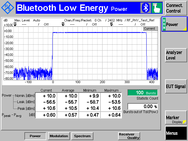
Output Power—RF-PHY/TRM/BV-01-C#
The power basic measurement is used to make all of the output power measurements.
In this example, the test_dtm_tx_v4 command is used.
In this test mode, only the frequency and the output power are configurable parameters.
A spectrum analyzer is used to measure the power of the radio and must be connected through a compatible RF cable to the RF connector of the radio board.
It is also possible to test the output power with a separate Bluetooth tester device when the DTM firmware is installed in the DUT.
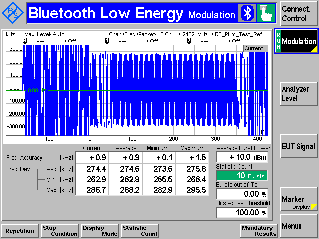
Modulation—RF-PHY/TRM/BV-05-C and RF-PHY/TRM/BV-06-C#
Used to make the modulation, and frequency offset and drift measurements.
In this example, the test_dtm_tx_v4 command is used.
To follow the test specification, you need to be able to change your payload data pattern (either 1010 pattern or 11110000 pattern).
A spectrum analyzer is used to measure the modulation, frequency offset, and drift measurements of the radio and must be connected through a compatible RF cable to the RF connector of the radio board.
It is also possible to test by using a separate Bluetooth tester device provided that the DTM firmware is installed in the DUT.
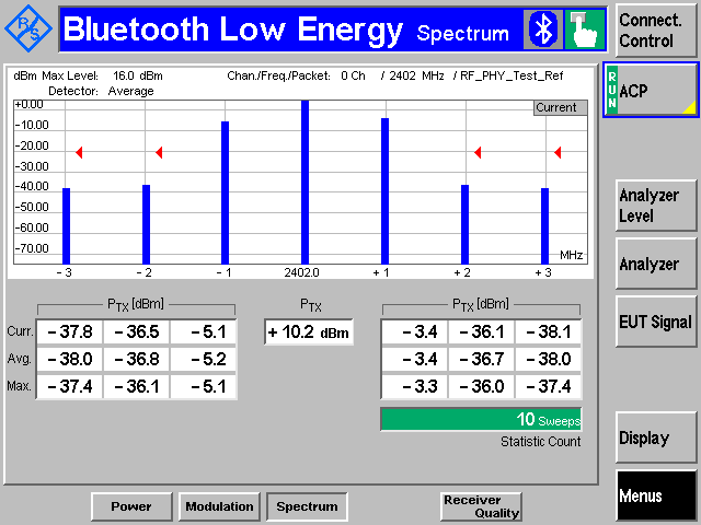
Spectrum—RF-PHY/TRM/BV-03-C#
Used for in-band emissions measurements.
In this example, the test_dtm_tx_v4 command is used.
A spectrum analyzer is used to measure the spectrum of the radio and must be connected through a compatible RF cable to the RF connector of the radio board.
It is also possible to use a separate Bluetooth tester device provided that the DTM firmware is installed in the DUT.
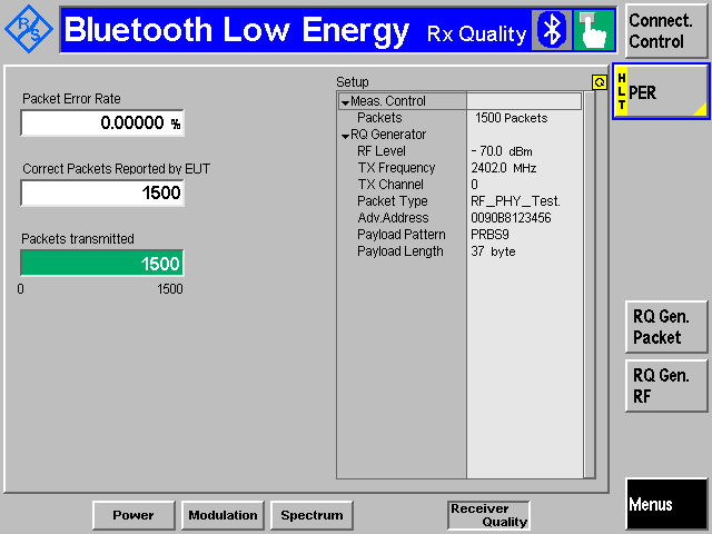
Receiver Tests#
Used to make all of the sensitivity-based measurements, as well as blocker measurements.
In this example, the test_dtm_rx command is used. In Bluetooth NCP Commander Standalone, the test is started by selecting Low energy receive and then pressing the Start test button.
A spectrum analyzer and two RF generators are used to validate the receiver tests and must be connected through a compatible RF cable to the RF connector of the radio board.
A separate Bluetooth tester device can be used, but you might have to consider adding to it an external signal generator to provide the second interferer or blocker signal.