Bluetooth Mesh Stacks and Wireless Gecko Configuration and Resources#
To run the Bluetooth stack and an application on a Wireless Gecko, the MCU and its peripherals have to be properly configured. Once the hardware is initialized, the stack also has to be initialized using the sl_btmesh_init() function as described in section Stack. This process is automated by the SDK.
sl_system_init()
The sl_system_init() function is used to initialize the system. It will call platform, driver, service, stack, and internal app init functions, located in the autogen folder.
app_init()
This function is used to initialize application-specific features.
Wireless Gecko MCU and Peripherals Configuration#
If the specific configuration is supported under Bluetooth Mesh, its detailed explanation can be found in the Wireless Gecko MCU and Peripherals Configuration section of Configuring the Bluetooth Stack and a Wireless Gecko Device.
Configuration | Bluetooth Mesh |
|---|---|
Adaptive Frequency Hopping | Not supported when using the advertising bearer, as all data traffic uses the primary advertising channels. If the GATT bearer is used, Bluetooth mesh data are sent and received via the Proxy protocol, which uses a Bluetooth Low Energy connection with dedicated Bluetooth mesh services. |
Bluetooth Clocks | Supported. |
DC-DC Configuration | Supported. |
LNA | Supported. |
Periodic Advertising | Not supported. Legacy advertising (31 bytes long) only, as per the profile specification. |
PTI | Supported. |
Transmit Power | Supported. |
Filter Accept List | Supported. |
Wi-Fi Coexistence | Supported. |
OTA Configuration | Supported using Bluetooth LE services. |
Even Connection Distribution Algorithm | Not supported. |
Interrupts | Supported |
Wireless Gecko Resources#
The Bluetooth mesh stack uses some of the Wireless Gecko’s resources, which are not available to the application. The following table lists the resources and describes their use by the stack. The first four resources are always used by the Bluetooth stack.
Category | Resource | Used in software | Notes |
|---|---|---|---|
PRS | PRS7 | PROTIMER RTC synchronization | PRS7 always used by the Bluetooth stack. |
Timers | RTCC | EM2 | The sleep timer uses RTCC in the default configuration. |
“ | PROTIMER | Bluetooth (LE and mesh) | The application does not have access to PROTIMER. |
Radio | RADIO | Bluetooth | Always used and all radio registers are reserved for the Bluetooth LE and mesh stack. |
GPIO | NCP | Host communication | Up to 4 I/O pin. Optional. |
“ | PTI | Packet trace | 2 to N I/O pins. Optional. |
“ | TX ACTIVE | TX activity indication | 1 I/O pin. Optional. |
“ | RX ACTIVE | RX activity indication | 1 I/O pin. Optional. |
“ | COEX PTA | Wi-Fi Coexistence | Up to 4 I/O pins. Optional. |
CRC | GPCRC | NVM3 | Can be used in application, but application should always reconfigure GPCRC before use, and GPCRC clock must not be disabled in CMU. |
Flash | MSC | NVM3 | Can be used by the application. |
Crypto | CRYPTO | Bluetooth Link encryption | The CRYPTO peripheral can only be accessed through the mbedTLS crypto library, not through any other means. The library should be able to do the scheduling between the stack and application access. |
“ | RADIO AES | Bluetooth Link encryption | The application does not have access to RADIOAES |
Internal Flash and SRAM#
For more information, refer to the Wireless Gecko Resources section in Silicon Labs Bluetooth C Application Developer's Guide for SDK v10.x.
Monitoring Radio RX and TX State Using PRS (Peripheral Reflex System)#
It is sometimes useful, for debugging purposes, to monitor the state of the radio transmitter/receiver. This can be done by outputting on pins the RX_ACTIVE and TX_ACTIVE signals. An example is provided here on how to do that on Series 2 devices (EFR32xG24-based Wireless Gecko starter kit).
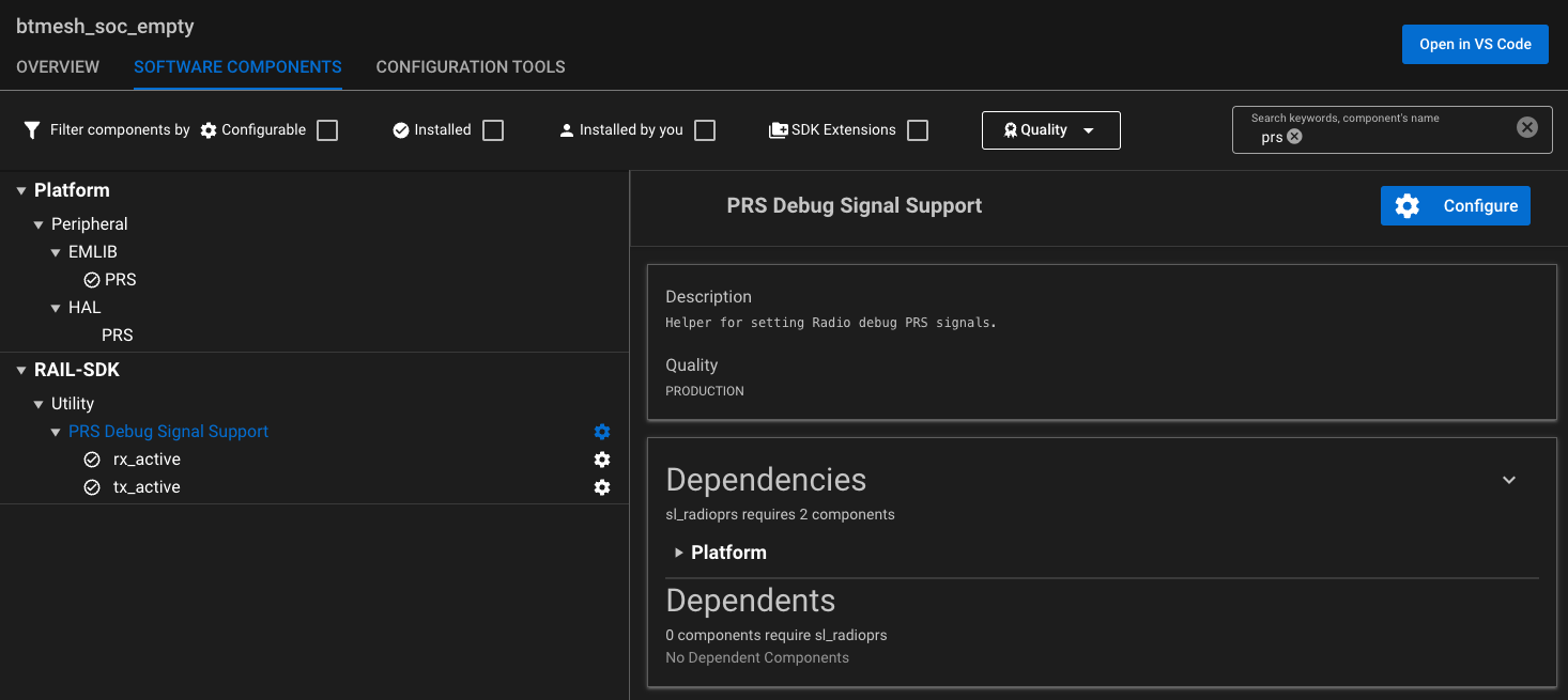
First, make sure the Platform → Peripheral → EMLIB → PRS component is installed in the project. Then the following configuration example indicates how PRS can be used to output the RX_ACTIVE and TX_ACTIVE signals.
Install two instances of the RAIL-SDK → Utility → PRS Debug Signal Support component:
Configure both of them:
Note: As indicated in the table in section Wireless Gecko Resources, PRS channel 7 is used by the Bluetooth LE stack and cannot be used in this example.
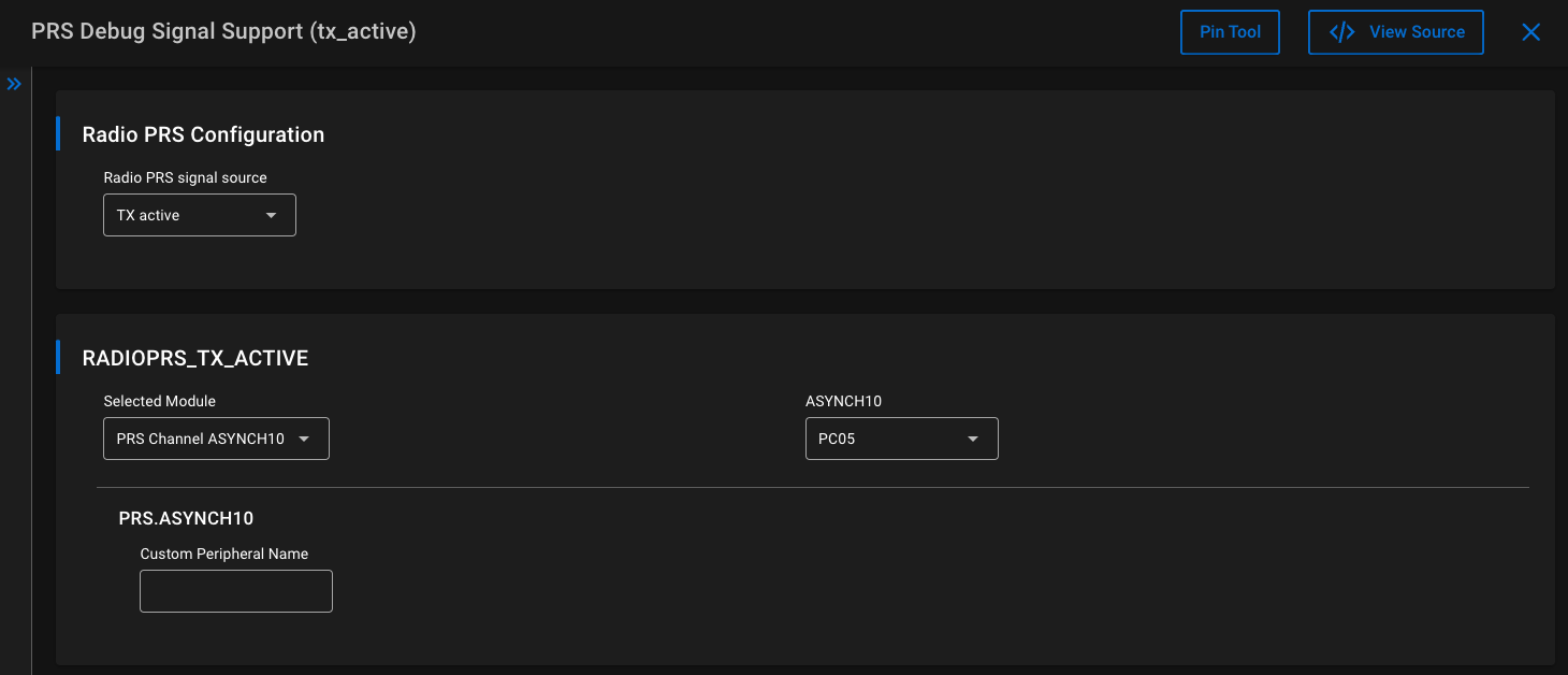
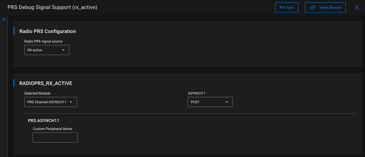
These configurations define which PRS signals coming from the radio source should be used. Those signals will then be routed to the desired pins, in this case PC05 (EXP PIN15) for the TX_ACTIVE signal and PC07 (EXP PIN16) for the RX_ACTIVE signal.
Then the following function sets up the pins and configure the PRS module (generated automatically in autogen/sl_radioprs_init_instances.c):
void sl_radioprs_init_instances(void)
{
sl_status_t clock_status = SL_STATUS_OK;
clock_status = sl_clock_manager_enable_bus_clock(SL_BUS_CLOCK_PRS);
if (clock_status != SL_STATUS_OK){
#ifdef SL_CATALOG_APP_LOG_PRESENT
app_log_warning("Clock manager returned with error code: %lu\n", clock_status);
#endif
return;
}
clock_status = sl_clock_manager_enable_bus_clock(SL_BUS_CLOCK_GPIO);
if (clock_status != SL_STATUS_OK){
#ifdef SL_CATALOG_APP_LOG_PRESENT
app_log_warning("Clock manager returned with error code: %lu\n", clock_status);
#endif
return;
}
// radioprs instance(s) init(s)
//begin radioprs_init_rx_active();
PRS_ConnectSignal(RADIOPRS_RX_ACTIVE_CHANNEL, prsTypeAsync, RADIOPRS_RX_ACTIVE_SOURCESEL);
PRS_PinOutput(RADIOPRS_RX_ACTIVE_CHANNEL, prsTypeAsync, RADIOPRS_RX_ACTIVE_PORT, RADIOPRS_RX_ACTIVE_PIN);
GPIO_PinModeSet(RADIOPRS_RX_ACTIVE_PORT, RADIOPRS_RX_ACTIVE_PIN, gpioModePushPullAlternate, 0);
//end radioprs_init_rx_active();
//begin radioprs_init_tx_active();
PRS_ConnectSignal(RADIOPRS_TX_ACTIVE_CHANNEL, prsTypeAsync, RADIOPRS_TX_ACTIVE_SOURCESEL);
PRS_PinOutput(RADIOPRS_TX_ACTIVE_CHANNEL, prsTypeAsync, RADIOPRS_TX_ACTIVE_PORT, RADIOPRS_TX_ACTIVE_PIN);
GPIO_PinModeSet(RADIOPRS_TX_ACTIVE_PORT, RADIOPRS_TX_ACTIVE_PIN, gpioModePushPullAlternate, 0);
//end radioprs_init_tx_active();
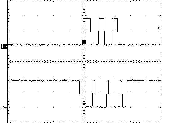
}The radio state can then be monitored using the defined pins on a logic analyzer or oscilloscope. In this example, the radio is running a simple Bluetooth Mesh SoC Empty example, waiting to be provisioned. On each of the three primary advertising channels, data is first transmitted (Channel 1 - long logic high) then the radio switches to the receive state (Channel 2 - short logic high), which is repeated on each channel.