PTA Support Software Setup#
Note: GPIO interrupt numbers are based on the GPIO pin numbers and not the port. This can cause conflicts if the same pin is selected for different ports—for example, PD15 will conflict with PB15. Silicon Labs recommends avoiding these conflicts. If the conflict exists in hardware, manual macros can be added with the assistance of Silicon Labs Support.
Standard Project Configuration#
To enable PTA coexistence support, the following steps are required:
Create a Bluetooth or Bluetooth Mesh project in Simplicity Studio v6.
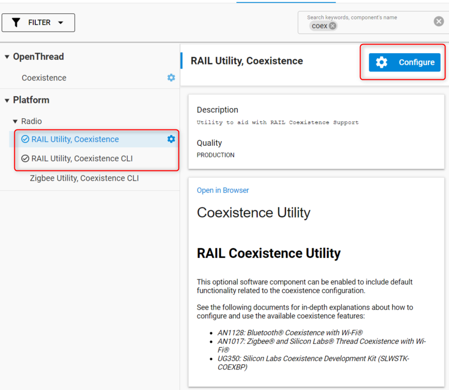
In the .slcp file of the project, navigate to Software Components and Install RAIL Utility, Coexistence and RAIL Utility, Coexistence CLI if not installed already and then click Configure.
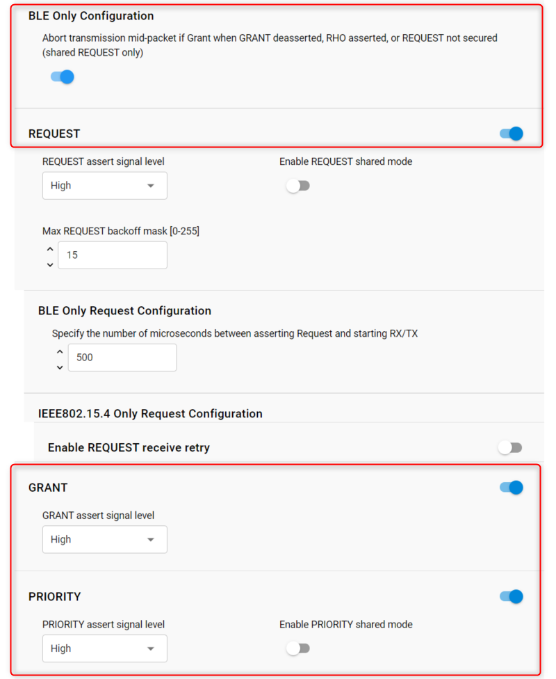
The polarity of the signals can be left unchanged. In the case of multiple EFR32s, the “shared mode” for each signal can be activated. For the common PTA 3 wire configuration, select the REQUEST, GRANT, and PRIORITY signals as shown.
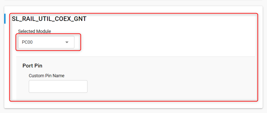
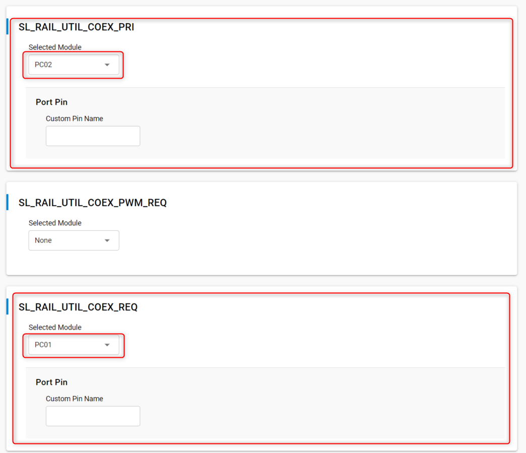
For each signal, select the corresponding GPIO:
Finally, for debug purposes, ensure that the PRS and PTI components are installed in your project.
PWM|REQUEST Project Configuration#
In case high duty-cycle is required for high Wi-Fi throughput, the “PWM” feature offers a way for EFRs to pull up the REQUEST signal in a way that improves the probabilities to get a time slot granted from the PTA central device. For more details on the feature, refer to Wi-Fi Coexistence Fundamentals.
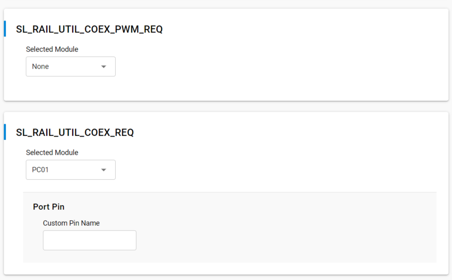
In this particular case, the SL_RAIL_UTIL_COEX_REQ signal corresponds to the REQUEST back-channel. The SL_RAIL_UTIL_COEX_PWM_REQ corresponds to the PWM|REQ signal between the EFR(s) and the Wi-Fi chip.
PTA Signals#
This section clarifies the settings that are specific to each signal.
REQUEST Signal#
BLE Only Request Configuration (Request Window)
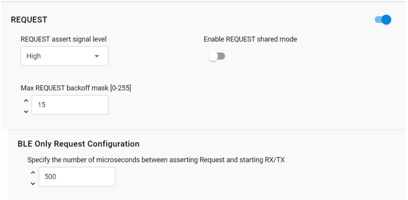
REQUEST Window adjusts the lead time for REQUEST assertion before the first Bluetooth TX or RX operation and after the REQUEST is asserted. A TX operation will proceed if GRANT is asserted at the end of the REQUEST Window. An RX operation will attempt to proceed regardless of GRANT asserted or de-asserted as Bluetooth RX does not transmit energy and hence does not impact other co-located radios. This feature’s setting needs to at least exceed the maximum time for Wi-Fi/PTA to provide GRANT asserted or de-asserted after the REQUEST is asserted.
REQUEST signal is shared
This helps the radio transceiver software to set the electrical status of the corresponding GPIO so it can be driven by other EFRs (open-drain). This should be disabled for single EFR operation.
REQUEST signal max backoff mask
REQUEST signal max backoff determines the random REQUEST delay mask (only valid if REQUEST signal is shared). The random delay (in µs) is computed by masking the internal random variable against the entered mask. The mask should be set to a value of 2n-1 to ensure a continuous random delay range.
Some Wi-Fi/PTA terminologies also refer REQUEST signal as BT_ACTIVE.
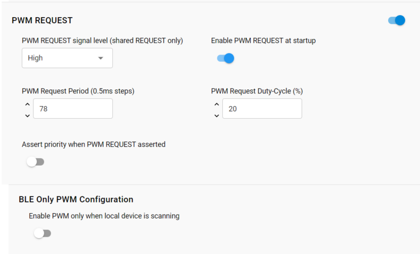
In case the PWM feature is used:
PWM asserts REQUEST and optionally PRIORITY at a regular period and duty-cycle. PWM can be employed to create idle Wi-Fi TX windows to improve 100% Passive SCAN performance and is essential for Bluetooth mesh using ADV-Bearer to allow sufficient idle Wi-Fi TX time windows. PWM Request Period and PWM Request Duty-Cycle indicates the period and duty-cycle at reset.
PWM period should not be an integer sub-multiple of Wi-Fi beacon (typically 102.4 ms). This is required to prevent Wi-Fi from losing many beacons and disassociating. Also, the lowest duty-cycle providing sufficient BT performance is recommended as higher PWM duty-cycles reduce RF time available to Wi-Fi with associated reduction in Wi-Fi throughput.
However, for Bluetooth mesh using the ADV-Bearer method, a period of 39 ms and duty-cycle greater than 44% may be required to receive 99% of ADV-bearer messages (exact PWM requirement depends on Bluetooth mesh retry settings). If possible, Bluetooth mesh should use the GATT-bearer method from the co-located Bluetooth mesh radio to relay node.
If Assert priority when PWM REQUEST asserted is enabled, then REQUEST is Shared REQUEST between multiple EFR32 radios and is used to arbitrate which EFR32 controls PTA interface to Wi-Fi. Operating PWM on Shared REQUEST is incompatible with arbitration. As such, the PWM_REQUEST pin becomes necessary. Shared REQUEST interconnects all EFR32 radios for arbitration and PWM_REQUEST is connected to all EFR32 radios, but drives the REQUEST signal to Wi-Fi/PTA.
If Assert priority when PWM REQUEST asserted is disabled, then REQUEST is not shared and is used to drive all PTA requests to Wi-Fi, both from radio states requests and from PWM.
GRANT Signal#
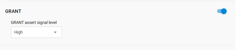
Many Wi-Fi/PTA devices refer GRANT with the term WLAN_ACTIVE. In other cases GRANT is referred as WLAN_DENY or BT_DENY and is active-high. These active-high deny signals correlate with EFR32 active-low GRANT.
In 1-wire PTA configurations based on REQUEST-only, GRANT is not implemented. If GRANT is not needed, you can disable the signal.
TX Abort#
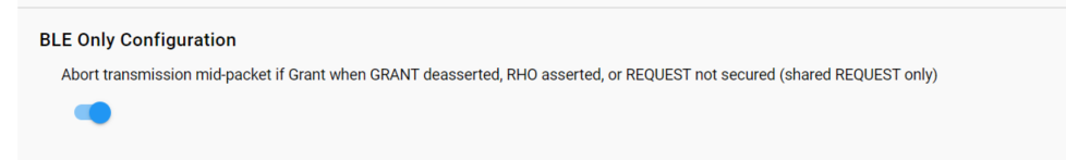
If enabled, Bluetooth transmission will be aborted when GRANT/RHO/REQUEST are de-asserted. If disabled, losing GRANT (or RHO asserted) after the start of a Bluetooth TX will not abort the Bluetooth TX.
PRIORITY Signal#

Note: In 1-Wire or 2-Wire PTA configurations, PRIORITY is not implemented. For single EFR operation, the shared mode for PRIORITY should be disabled
Radio Hold Off#
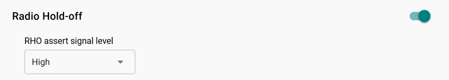
Radio hold-off (RHO) is effectively a second GRANT signal. However, when RHO is asserted, Bluetooth TX operations are blocked.
Note: In most EFR32 coexistence applications, RHO is not needed. If RHO is not needed it can be disabled.
Signal Identifier (Supported Devices Only)#
On supported device families, such as the EFR32xG24, a hardware feature allows the radio transceiver driver to take advantage of interframe spaces in Wi-Fi transmissions. This feature enables a signal detector to search for IoT signal characteristics (802.15.4 and BLE) during Wi-Fi transmission. It can significantly improve RX performance, even in high-duty-cycle Wi-Fi environments.
For more information about how this feature works, see Wi-Fi Coexistence Fundamentals.
The following configuration options are available.
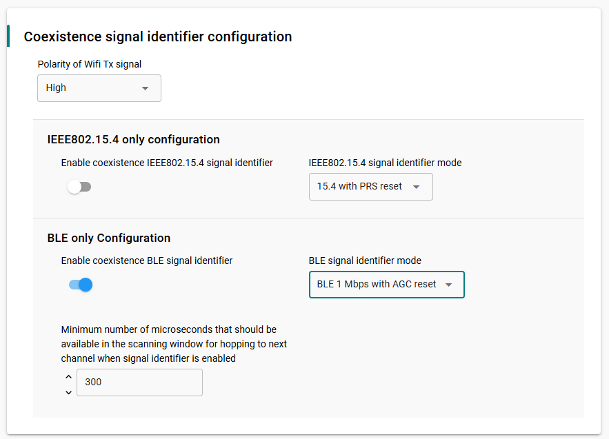
Enable coexistence BLE signal identifier#
Enables the signal identifier during BLE radio operation.
BLE signal identifier mode#
BLE 1 Mbps/2 Mbps with PRS reset: Uses an external Wi-Fi TX enabled signal to reset the internal signal detector. If this option is selected, configure the GPIO and signal polarity to match the hardware design.
BLE 1 Mbps/2 Mbps with AGC reset: Uses internal radio signals to reset the signal detector. No external GPIO connection is required.
Polarity of Wi-Fi TX signal#
Configure this option only when using a GPIO-based signal identifier configuration.
Set this parameter to match the polarity of the incoming Wi-Fi TX enabled signal.
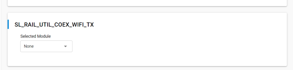
SL_RAIL_UTIL_COEX_WIFI_TX#
Configure this option only when using a GPIO-based signal identifier configuration.
Use this field to configure the PRS module and GPIO pin that carry the Wi-Fi TX enabled signal.
The following screenshots show how to configure the Signal Identifier feature and the corresponding Wi-Fi TX GPIO.
Directional Priority#
PRIORITY can be “static” where it is asserted or de-asserted for the entire TX/RX/… or RX/TX/… event. Directional PRIORITY can be used to provide priority information and radio state (TX or RX). The EFR32 implementation of Directional PRIORITY is accomplished using static PRIORITY, REQUEST (or PWM_REQUEST if multi-EFR32 using Shared REQUEST), a TIMER, and up to 6 PRS channels. Because on-chip hardware resources are used with this feature, it is very important to understand which are used and ensure no conflicts. Directional PRIORITY is only supported for PTA implementations where REQUEST (PWM_REQUEST) and PRIORITY are active high.
As illustrated in PTA 3-Wire BLE Functional Overview, the Directional PRIORITY signal is a combination of other signals:
Static PRIORITY signal.
The REQUEST signal.
Radio controller state “FEM” (Front End Module) signals. In particular, RACPAEN which is the signal corresponding to the Power Amplifier on the transmit path.
A Hardware timer for Directional PRIORITY time pulses.
Additional PRS channels needed for signal routing.
For more details on the mechanisms used to generate the Directional Priority signal, refer to Wi-Fi Coexistence Fundamentals.
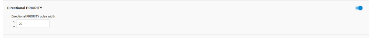
If enabled, Directional PRIORITY drives a programmable pulse-width (1µs to 255µs) to indicate the priority of TX/RX/… or the priority of RX/TX/… events. Following pulse, Directional PRIORITY signal is low for radio in RX state and high for radio in TX state. The Wi-Fi/PTA device can monitor the Directional PRIORITY signals to understand the priority of the TX/RX/… or RX/TX/… event and the current radio state. In this manner, simultaneous TX/TX and RX/RX can be allowed and conflicting TX/RX and RX/TX events can be prioritized by PTA mechanism.
To enable Directional PRIORITY, start by turning on the feature in the RAIL Utility, Coexistence component.
When the component UI is modified, the corresponding coexistence configuration files under the config directory in your project are automatically modified to reflect your latest changes:
sl_rail_util_coex_common_config.h
sl_rail_util_coex_config.h
The first file (sl_rail_util_coex_common_config.h) contains macros that are software switches for each coexistence feature.
The second file (sl_rail_util_coex_config.h) defines the hardware Inputs/Outputs and PRS and Timer peripherals.
The PRIORITY signal is not assigned a GPIO and is set disabled. It has no physical connection to the Wi-Fi PTA and is used as Static PRIORITY input to the Directional PRIORITY logic block with the remaining PRIORITY signal configuration options.
Note: Component UI for PRIORITY configuration fields are disabled and therefore not editable when Enable PRIORITY is set to true. A workaround is to assign any GPIO to PRIORITY signal, edit the PRIORITY configuration options, and then set PRIORITY signal to disabled. This is valid for SDKs prior to GSDK 4.1.1.
Enable REQUEST, GRANT and Directional PRIORITY (the PRIORITY signal should also be enabled).
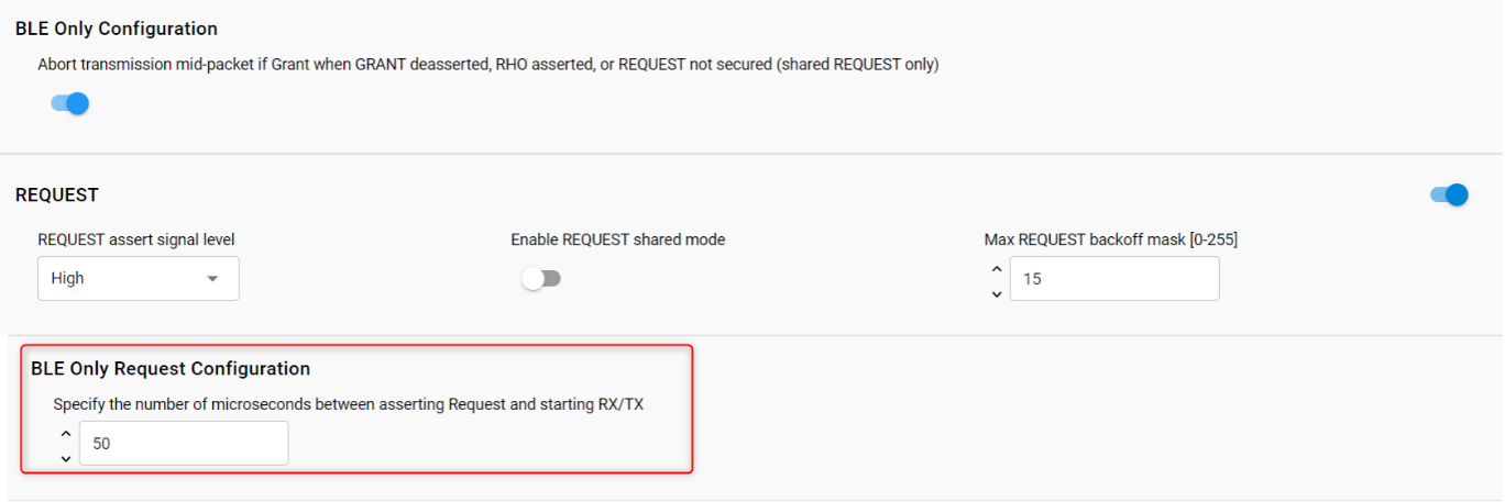
Under the REQUEST signal set "Specify the number of microseconds between asserting Request and starting RX/TX" to 50 us for example.
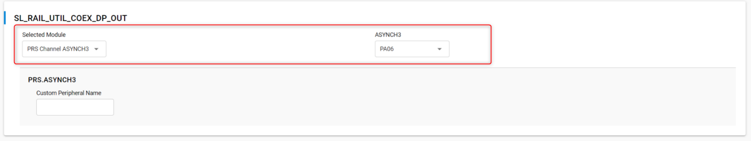
Set the pin settings for SL_RAIL_UTIL_COEX_GNT, SL_RAIL_UTIL_COEX_REQ, and SL_RAIL_UTIL_COEX_DP_OUT.
Note that, for series 1, the signal SL_RAIL_UTIL_COEX_DP_REQUEST_INV should also be set according to the wanted polarity.
In some earlier version of the GSDK (prior to 4.1.1), the timer settings aren’t present by default in the component definition. In this case it has to be added manually by copy pasting the following snippet of code in the file "config/sl_rail_coex_config.h" and add the timer macros. This gives the expected Hardware Timer settings in the “RAIL Utility, Coexistence” component UI:
// Directional Priority timer module // <timer channel=CC0 optional=true> SL_RAIL_UTIL_COEX_DP_TIMER // $[TIMER_SL_RAIL_UTIL_COEX_DP_TIMER] #define SL_RAIL_UTIL_COEX_DP_TIMER_PERIPHERAL TIMER1 #define SL_RAIL_UTIL_COEX_DP_TIMER_PERIPHERAL_NO 1 // [TIMER_SL_RAIL_UTIL_COEX_DP_TIMER]$ #ifndef SL_RAIL_UTIL_COEX_DP_TIMER_PERIPHERAL #error "SL_RAIL_UTIL_COEX_DP_TIMER_PERIPHERAL undefined" #endif //SL_RAIL_UTIL_COEX_DP_TIMER_PERIPHERAL #endif //SL_RAIL_UTIL_COEX_DP_ENABLED #endif // SL_RAIL_UTIL_COEX_CONFIG_H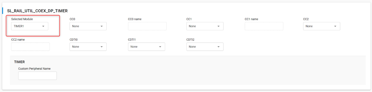
Note: REQUEST will assert on valid BLE preamble/sync. REQUEST will also stay asserted through any follow-up TX/RX/... required for this RX packet.
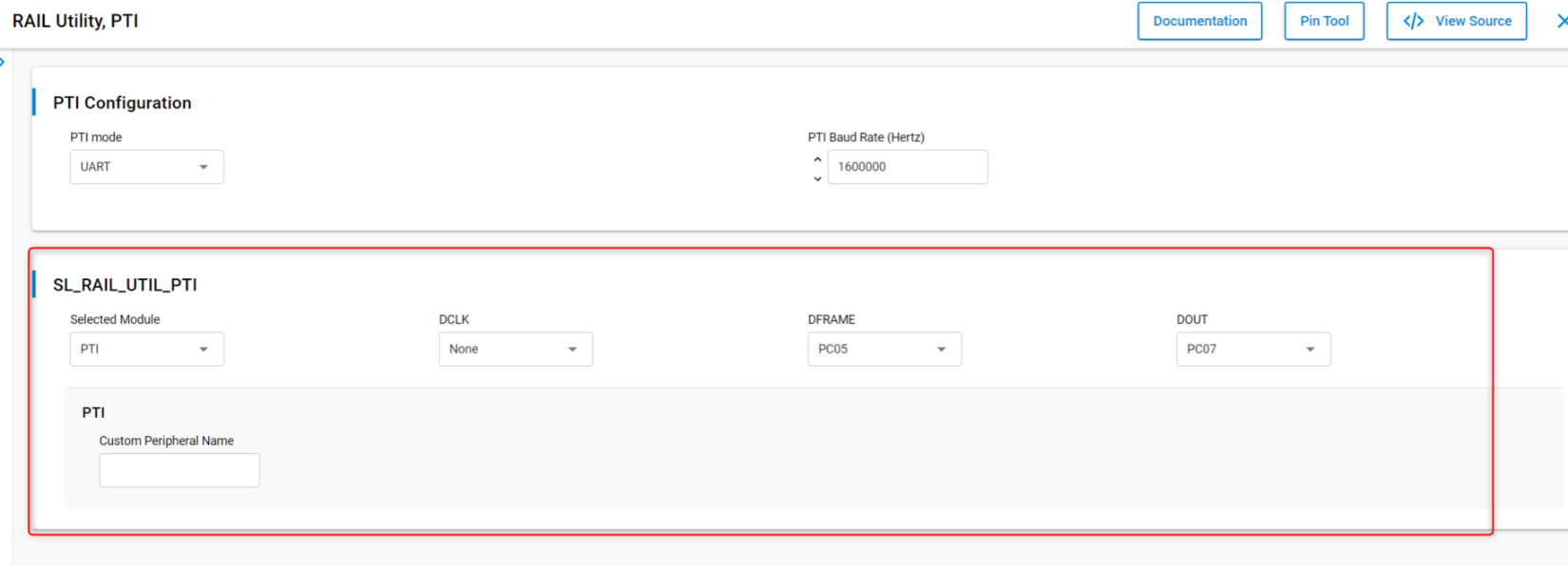
As an extra, the FEM and PTI pins can be set so that the data being sent appear on the logic analyzer waveforms. To do so, in the RAIL Utility, PTI component, configure the desired signals as illustrated:
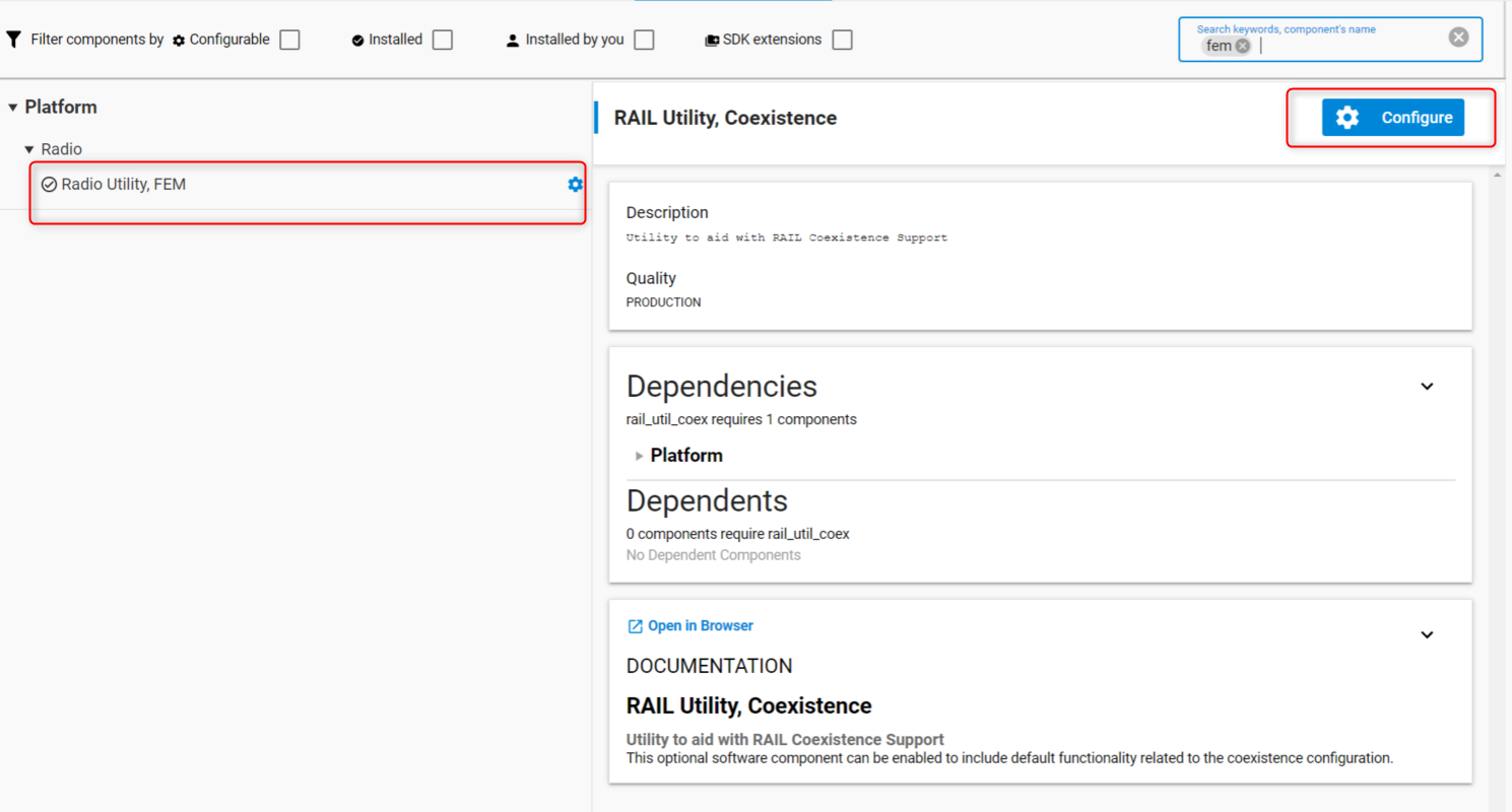
Install the FEM component Radio Utility, FEM (this section is optional – for debugging purposes):
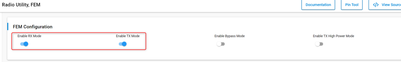
In that component, in the FEM Configuration pane, toggle on Enable RX Mode and Enable TX Mode.
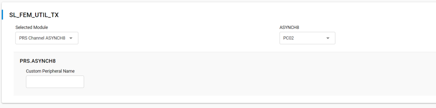
Then after enabling the RX (Radio Controller LNA or RACLNA Enabled in short) and TX (Radio Controller PA signals or RACPA Enabled used for DP generation), set the RX (RACLNAEN) and TX (RACPAEN) pins.

An example of signals waveform generated (BLE active scanning) by a project configured as above would look like the following on a logic analyzer:
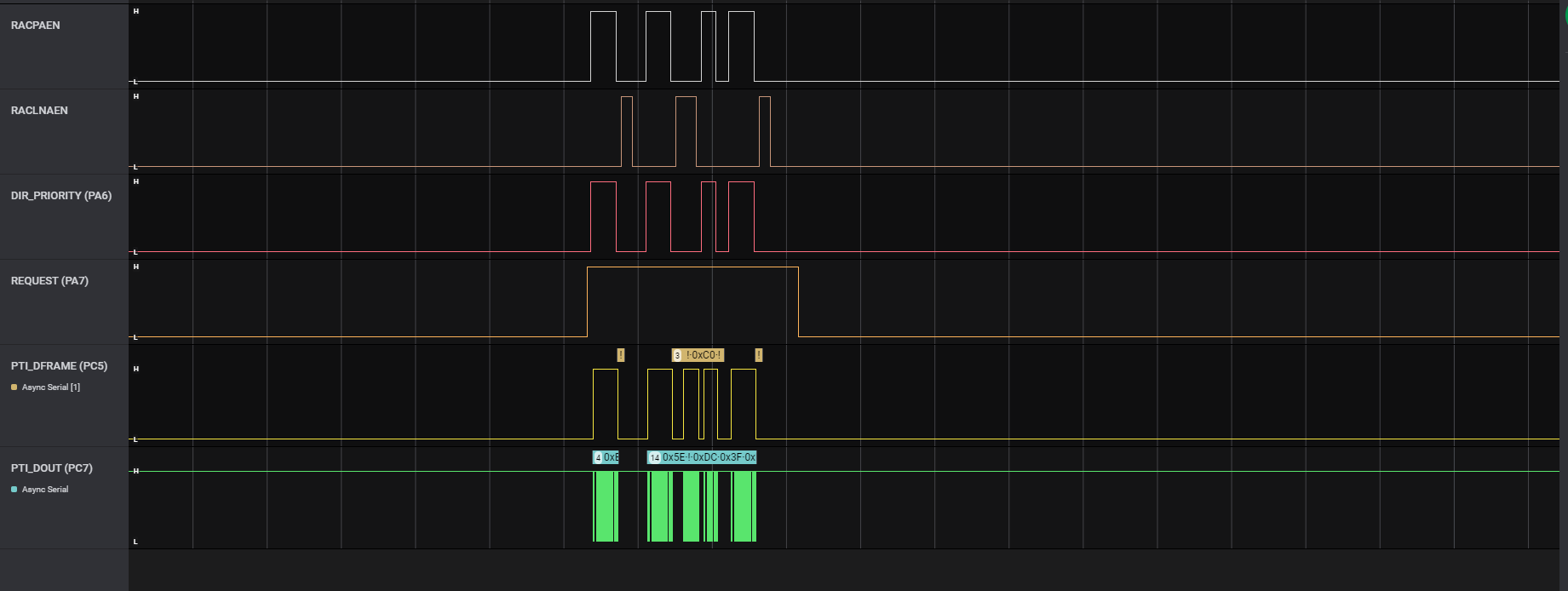
The above illustrates a BLE advertising packet being sent on the three primary channels. You can see the RACPAEN pull up during transmit and then RACLNAEN begin pulled up for a short while. The second advertising has an active scanning packet (RACPAEN being pulled after reception for a little while).
Run-Time PTA Re-configuration#
The following PTA options can also be re-configured at runtime:
Disable/Enable the PTA feature
At runtime, the following code disables the PTA feature:
sl_bt_coex_set_options(sl_bt_coex_option_enable, 0);At runtime, the following code enables the PTA feature:
sl_bt_coex_set_options(sl_bt_coex_option_enable, sl_bt_coex_option_enable);Abort transmission mid packet if GRANT is lost.
At runtime, the following code disables Abort transmission mid packet if GRANT is lost:
sl_bt_coex_set_options(sl_bt_coex_option_tx_abort, 0);At runtime, the following code enables Abort transmission mid packet if GRANT is lost:
sl_bt_coex_set_options(sl_bt_coex_option_tx_abort, sl_bt_coex_option_tx_abort);PRIORITY Escalation capability
At runtime, the following code disables PRIORITY assertion:
sl_bt_coex_set_options(sl_bt_coex_option_high_priority, 0);At runtime, the following code enables PRIORITY assertion:
sl_bt_coex_set_options(sl_bt_coex_option_high_priority, sl_bt_coex_option_high_priority);Channel Map Masking
If an EFR32 device enters CONNECTION state as a central device, it controls which of the 37 data channels are used during the AFH. As a CONNECTION central device, the EFR32 can also update this channel map and communicate this update to a peripheral device. This feature can be used to make Bluetooth avoid being co-channel to Wi-Fi.
If EFR32 becomes the connection central device, the Bluetooth channel map can be specified using this function call:
sl_bt_gap_set_data_channel_classification (size_t channel_map_len, const uint8_t * channel_map)This command can be used to specify a channel classification for data channels. This classification persists until overwritten with a subsequent command or until the system is reset.
channel_mapis a 5 byte bit field in little endian format and the first 37 bits are used. The nth such field (in the range 0 to 36) contains the value for the link layer channel index n:0: Channel n is bad.
1: Channel n is unknown.
The most significant bits are reserved and shall be set to 0. At least two channels shall be marked as unknown.
Other Parameters
The priorities of when the PRIORITY and REQUEST should be toggled can be controlled in runtime by modifying the thresholds. This allows application to control radio time allocation across protocols in runtime.
Also, the PWM period and duty cycle can be adjusted in runtime. These settings can be changed at run time using this function call:
sl_bt_coex_set_parameters (uint8_t priority, uint8_t request, uint8_t pwm_period, uint8_t pwm_dutycycle)Link Layer Priority Table
It may be required during application execution to change the link layer priorities. This can be changed at run time using these functional calls:
sl_bt_system_linklayer_configure (uint8_t key, size_t data_len, const uint8_t * data)where
keyshould besl_bt_system_linklayer_config_key_set_priority_tabledatais in the format ofsl_btctrl_ll_prioritiesas below:typedef struct { uint8_t scan_min; uint8_t scan_max; uint8_t adv_min; uint8_t adv_max; uint8_t conn_min; uint8_t conn_max; uint8_t init_min; uint8_t init_max; uint8_t rail_mapping_offset; uint8_t rail_mapping_range; uint8_t rfu; uint8_t adv_step; uint8_t scan_step; uint8_t pawr_tx_min; uint8_t pawr_tx_max; uint8_t pawr_rx_min; uint8_t pawr_rx_max; } sl_btctrl_ll_priorities;This full array is 17 bytes in length. However, if
data_lenis less than 17, only firstdata_lenentries will be modified. For example, ifdata_len=2, onlyscan_minandscan_maxare updated.
Run-Time PTA Debug Counters#
At runtime, PTA Debug Counters are also available and can be accessed and reset via the following function:
sl_bt_coex_get_counters(uint8_t reset, size_t max_counters_size, size_t *counters_len, uint8_t *counters);where:
reset = 0leaves counters unchangedreset = 1resets all counters to 0 (after reading current counter values)where, since startup or last reset:
max_counters_sizeis the size of output buffer passed incounters.counters_lenon return, is set to the length of output data written tocounters.countersis the counters buffer.Counters in the list are in following order: low priority requested, high priority requested, low priority denied, high priority denied, low-priority TX aborted, and high-priority TX aborted. Passing a non-zero value also resets counter.
Coexistence Configuration Setup Examples for Different Wi-Fi/PTA Applications#
Example 1: Configure EFR32 PTA support to operate as single EFR32 with typical 3-Wire Wi-Fi/PTA#
Single EFR32 radio
REQUEST unshared, active high, PC02
Compatible 3-Wire Wi-Fi/PTA devices sometimes refer to this signal as RF_ACTIVE or BT_ACTIVE (active high)
GRANT, active low, PC00
Compatible 3-Wire Wi-Fi/PTA devices sometimes refer to this signal as WLAN_DENY (deny is active high, making grant active low)
PRIORITY, active high, PC01
Compatible 3-Wire Wi-Fi/PTA devices sometimes refer to this signal as RF_STATUS or BT_STATUS (active high)
PRIORITY is static, not directional. If operated with a 3-Wire Wi-Fi/PTA expecting directional:
Static high PRIORITY is interpreted as high PRIORITY and always in TX mode, regardless of actual TX or RX
Static low PRIORITY is interpreted as low PRIORITY and always in RX mode, regardless of actual TX or RX
REQUEST_WINDOW is 500 µs
Disabled Abort transmission mid packet if GRANT is lost
PRIORITY is always high
RHO unused
The required #defines in sl_rail_util_coex_config.h and sl_rail_util_coex_common_config.h are:
// $[SL_RAIL_UTIL_COEX_COMMON_CONFIG_H]
#define SL_RAIL_UTIL_COEX_BLE_TX_ABORT 0
#define SL_RAIL_UTIL_COEX_REQ_ENABLED 1
#define SL_RAIL_UTIL_COEX_REQ_ASSERT_LEVEL 1
#define SL_RAIL_UTIL_COEX_REQ_SHARED 0
#define SL_RAIL_UTIL_COEX_REQ_BACKOFF 15
#define SL_RAIL_UTIL_COEX_REQ_WINDOW 500
#define SL_RAIL_UTIL_COEX_GNT_ENABLED 1
#define SL_RAIL_UTIL_COEX_GNT_ASSERT_LEVEL 0
#define SL_RAIL_UTIL_COEX_PRI_ENABLED 1
#define SL_RAIL_UTIL_COEX_PRI_ASSERT_LEVEL 1
#define SL_RAIL_UTIL_COEX_PRI_SHARED 0
#define SL_RAIL_UTIL_COEX_PRIORITY_DEFAULT 1
#define SL_RAIL_UTIL_COEX_PWM_REQ_ENABLED 0
#define SL_RAIL_UTIL_COEX_PWM_DEFAULT_ENABLED 0
#define SL_RAIL_UTIL_COEX_DP_ENABLED 0
#define SL_RAIL_UTIL_COEX_RX_ACTIVE_ENABLED 0
// [SL_RAIL_UTIL_COEX_COMMON_CONFIG_H]$
// $[SL_RAIL_UTIL_COEX_CONFIG_H]
#define SL_RAIL_UTIL_COEX_GNT_PORT SL_GPIO_PORT_C
#define SL_RAIL_UTIL_COEX_GNT_PIN 0
#define SL_RAIL_UTIL_COEX_PRI_PORT SL_GPIO_PORT_C
#define SL_RAIL_UTIL_COEX_PRI_PIN 1
#define SL_RAIL_UTIL_COEX_REQ_PORT SL_GPIO_PORT_C
#define SL_RAIL_UTIL_COEX_REQ_PIN 2
// [SL_RAIL_UTIL_COEX_CONFIG_H]$The logic analyzer capture in the following figure shows the PTA interface, Wi-Fi TX state, and EFR32 radio state for an EFR32 radio configured for typical 3-Wire Wi-Fi/PTA during a CONNECTION event (peripheral):
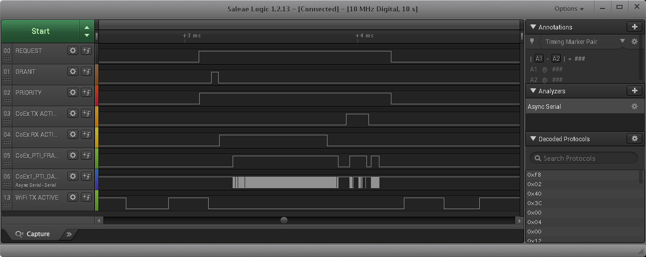
where:
REQUEST: active high, push-pull REQUEST output
GRANT: active low GRANT input
PRIORITY: active high PRIORITY output
CoEx TX ACTIVE: EFR32 TX Active control signal (configured via sample code in Application Code Coexistence Extensions)
CoEx RX ACTIVE: EFR32 RX Active control signal (configured via sample code in Application Code Coexistence Extensions)
CoEx PTI FRAME: EFR32 Frame Control Data Frame signal (packet trace frame/synch)
CoEx PTI DATA: EFR32 Frame Control Data Out signal (packet trace data)
WiFi TX ACTIVE: Wi-Fi TX Active signal
The logic analyzer sequence above shows:
Wi-Fi is transmitting and EFR32 asserts REQUEST, then high PRIORITY.
GRANT is momentarily de-asserted by Wi-Fi/PTA but is reasserted as Wi-Fi finished TX/RX.
EFR32 radio enables RX mode awaiting central TX.
EFR32 radio receives the central TX.
EFR32 radio exits receive mode.
At start of 150µs IFS, EFR32 radio transmits back to central.
After transmit, EFR32 de-asserts PRIORITY and then REQUEST.
Wi-Fi resumes transmission.
Example 2: Configure EFR32 PTA support to operate with multi-radio 2-Wire PTA with active-low REQUEST#
Multiple EFR32 radios (external 1 kΩ ±5% pull-up required on REQUEST)
REQUEST shared, active low, PC02
GRANT, active low, PC00
PRIORITY unused
REQUEST_WINDOW is 500 µs
Disabled Abort transmission mid packet if GRANT is lost
RHO unused
The required #defines in sl_rail_util_coex_common_config.h and sl_rail_util_coex_config.h are:
// $[SL_RAIL_UTIL_COEX_COMMON_CONFIG_H]
#define SL_RAIL_UTIL_COEX_BLE_TX_ABORT 0
#define SL_RAIL_UTIL_COEX_REQ_ENABLED 1
#define SL_RAIL_UTIL_COEX_REQ_ASSERT_LEVEL 0
#define SL_RAIL_UTIL_COEX_REQ_SHARED 1
#define SL_RAIL_UTIL_COEX_REQ_BACKOFF 15
#define SL_RAIL_UTIL_COEX_REQ_WINDOW 500
#define SL_RAIL_UTIL_COEX_GNT_ENABLED 1
#define SL_RAIL_UTIL_COEX_GNT_ASSERT_LEVEL 0
#define SL_RAIL_UTIL_COEX_PWM_REQ_ENABLED 0
#define SL_RAIL_UTIL_COEX_DP_ENABLED 0
#define SL_RAIL_UTIL_COEX_RX_ACTIVE_ENABLED 0
// [SL_RAIL_UTIL_COEX_COMMON_CONFIG_H]$
// $[SL_RAIL_UTIL_COEX_CONFIG_H]
#define SL_RAIL_UTIL_COEX_GNT_PORT SL_GPIO_PORT_C
#define SL_RAIL_UTIL_COEX_GNT_PIN 0
#define SL_RAIL_UTIL_COEX_REQ_PORT SL_GPIO_PORT_C
#define SL_RAIL_UTIL_COEX_REQ_PIN 2
// [SL_RAIL_UTIL_COEX_CONFIG_H]$The logic analyzer capture below shows the PTA interface, Wi-Fi radio state, and EFR32 radio state for an EFR32 radio configured for multi-radio 2-Wire PTA with active-low REQUEST:
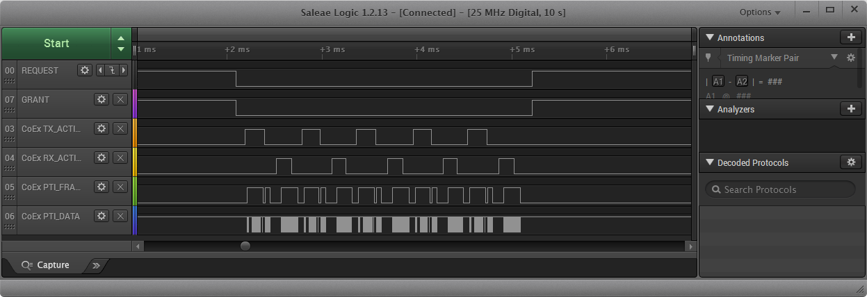
where:
REQUEST: active low, shared (open-drain) REQUEST input/output
GRANT: active low GRANT input
CoEx TX ACTIVE: EFR32 TX Active control signal (configured via sample code in Application Code Coexistence Extensions)
CoEx RX ACTIVE: EFR32 RX Active control signal (configured via sample code in Application Code Coexistence Extensions)
CoEx PTI FRAME: EFR32 Frame Control Data Frame signal (packet trace frame/synch)
CoEx PTI DATA: EFR32 Frame Control Data Out signal (packet trace data)
The logic analyzer sequence above shows:
At request window before the connection event, Shared REQUEST signal is tested and found not asserted by another EFR32 radio, so EFR32 radio asserts REQUEST.
Wi-Fi/PTA responds with GRANT asserted.
At the end of request window (start of connection event), EFR32 tests GRANT, which is asserted. In case the GRANT is not asserted at this point by the PTA Master, the transmission is aborted.
With GRANT asserted at start of CONNECTION event, EFR32 executes transmit.
After transmit is complete and before end of 150µs IFS, EFR32 enables receive to capture expected response from peripheral device.
EFR32 device receives and disables receive.
EFR32 repeats transmit/receive for four additional cycles as part of this first anchor point.
After last receive, EFR32 de-asserts REQUEST.
Wi-Fi/PTA responds with GRANT deasserted.