Application Code Coexistence Extensions#
Code Example TX_ACTIVE/RX_ACTIVE on Series 1 devices#
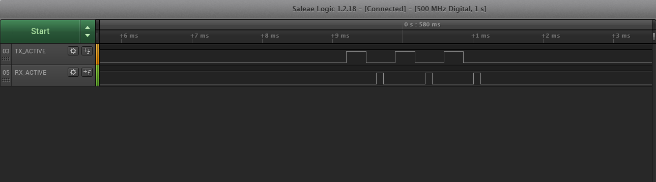
Note that Simplicity SDK does not support Series 1 devices. Use the latest Gecko SDK with Simplicity Studio v5 for this purpose. Use the latest Gecko SDK for this purpose. It is helpful to access the EFR32 radio state during PTA coexistence debugging. The following code examples create the TX_ACTIVE and RX_ACTIVE signals seen in the previous logic analyzer captures. This EFR32MG1P232F256GM48 example pushes TX_ACTIVE out PD10 and RX_ACTIVE out PD11. Other GPIOs can be used with changes in #defines. Consult the design-specific EFR32xG datasheet and reference manual for details on changing #defines values to other EFR32 devices and to alternate GPIOs.
// Enable TX_ACT signal through GPIO PD10
#define PRS_CH_CTRL_SOURCESEL_RAC2 (0x00000020UL<< 8)
#define PRS_CH_CTRL_SIGSEL_RACPAEN (0x00000004UL<< 0)
#define TX_ACTIVE_PRS_SOURCE PRS_CH_CTRL_SOURCESEL_RAC2
#define TX_ACTIVE_PRS_SIGNAL PRS_CH_CTRL_SIGSEL_RACPAEN
#define TX_ACTIVE_PRS_CHANNEL 5
#define TX_ACTIVE_PRS_LOCATION 0
#define TX_ACTIVE_PRS_PORT gpioPortD
#define TX_ACTIVE_PRS_PIN 10
#define TX_ACTIVE_PRS_ROUTELOC_REG ROUTELOC1
#define TX_ACTIVE_PRS_ROUTELOC_MASK (~0x00003F00UL)
#define TX_ACTIVE_PRS_ROUTELOC_VALUE PRS_ROUTELOC1_CH5LOC_LOC0 // PD10
#define TX_ACTIVE_PRS_ROUTEPEN PRS_ROUTEPEN_CH5PEN
// Enable RX_ACT signal through GPIO PD11
#define PRS_CH_CTRL_SOURCESEL_RAC2 (0x00000020UL<< 8)
#define PRS_CH_CTRL_SIGSEL_RACRX (0x00000002UL<< 0)
#define RX_ACTIVE_PRS_SOURCE PRS_CH_CTRL_SOURCESEL_RAC2
#define RX_ACTIVE_PRS_SIGNAL PRS_CH_CTRL_SIGSEL_RACRX
#define RX_ACTIVE_PRS_CHANNEL 6
#define RX_ACTIVE_PRS_LOCATION 13
#define RX_ACTIVE_PRS_PORT gpioPortD
#define RX_ACTIVE_PRS_PIN 11
#define RX_ACTIVE_PRS_ROUTELOC_REG ROUTELOC1
#define RX_ACTIVE_PRS_ROUTELOC_MASK (~0x003F0000UL)
#define RX_ACTIVE_PRS_ROUTELOC_VALUE PRS_ROUTELOC1_CH6LOC_LOC13 // PD11
#define RX_ACTIVE_PRS_ROUTEPEN PRS_ROUTEPEN_CH6PEN
CMU_ClockEnable(cmuClock_PRS, true); // enable clock to PRS
// Setup PRS input as TX_ACTIVE signal
PRS_SourceAsyncSignalSet(TX_ACTIVE_PRS_CHANNEL, TX_ACTIVE_PRS_SOURCE, TX_ACTIVE_PRS_SIGNAL);
// enable TX_ACTIVE output pin with initial value of 0
GPIO_PinModeSet(TX_ACTIVE_PRS_PORT, TX_ACTIVE_PRS_PIN, gpioModePushPull, 0);
// Route PRS CH/LOC to TX Active GPIO output
PRS->TX_ACTIVE_PRS_ROUTELOC_REG = (PRS->TX_ACTIVE_PRS_ROUTELOC_REG & TX_ACTIVE_PRS_ROUTELOC_MASK) | TX_ACTIVE_PRS_ROUTELOC_VALUE;
PRS->ROUTEPEN |= TX_ACTIVE_PRS_ROUTEPEN;
// Setup PRS input as RX_ACTIVE signal
PRS_SourceAsyncSignalSet(RX_ACTIVE_PRS_CHANNEL, RX_ACTIVE_PRS_SOURCE, RX_ACTIVE_PRS_SIGNAL);
// enable RX_ACTIVE output pin with initial value of 0
GPIO_PinModeSet(RX_ACTIVE_PRS_PORT, RX_ACTIVE_PRS_PIN, gpioModePushPull, 0);
// Route PRS CH/LOC to RX Active GPIO output
PRS->RX_ACTIVE_PRS_ROUTELOC_REG = (PRS->RX_ACTIVE_PRS_ROUTELOC_REG & RX_ACTIVE_PRS_ROUTELOC_MASK) | RX_ACTIVE_PRS_ROUTELOC_VALUE;
PRS->ROUTEPEN |= RX_ACTIVE_PRS_ROUTEPEN;Code Example TX_ACTIVE/RX_ACTIVE on Series 2 devices#
It is helpful to access the EFR32 radio state during PTA coexistence debugging. The following code examples create the TX_ACTIVE and RX_ACTIVE signals seen in the previous logic analyzer captures. This EFR32MG21 example pushes TX_ACTIVE out PD02 and RX_ACTIVE out PD03. Other GPIOs can be used with changes in #defines. Consult the design-specific EFR32xGxx reference manual to get information relative to PRS sources and signals. Note that on series 2, PRS channels aren’t available on all GPIO ports.
// Enable TX_ACT and RX_ACT signal through GPIO PD02 and PD03
/* Signals */
#define RAC_RX_PRS_SOURCE (0x00000031UL\<\< 8)
#define RAC_RX_PRS_SIGNAL (0x03)
#define RAC_RX_PRS_CHANNEL 6
#define RAC_RX_PRS_PORT gpioPortD
#define RAC_RX_PRS_PIN 2
#define RAC_TX_PRS_SOURCE PRS_ASYNC_CH CTRL_SOURCESEL_RAC
#define RAC_TX_PRS_SIGNAL (0x04)
#define RAC_TX_PRS_CHANNEL 7
#define RAC_TX_PRS_PORT gpioPortD
#define RAC_TX_PRS_PIN 3
static void initPrs(void)
{
/* On xG21 chips, PRS ASYNC Chan 6 11 are on port C/D. ASYNC chan 1 to 5 are on Port A/B. */
PRS_SourceAsyncSignalSet( RAC_RX_PRS_CHANNEL, RAC_RX_PRS_SOURCE, RAC_RX_PRS_SIGNAL);
PRS_SourceAsyncSignalSet( RAC_TX_PRS_CHANNEL, RAC_TX_PRS_SOURCE, RAC_TX_PRS_SIGNAL);
/* Route output to PD02/PD03. No extra PRS logic needed here. */
PRS_PinOutput(RAC_RX_PRS_CHANNEL,prsTypeAsync, RAC_RX_PRS_PORT , RAC_RX_PRS_PIN);
PRS_PinOutput(RAC_TX_PRS_CHANNEL,prsTypeAsync, RAC_TX_PRS_PORT , RAC_TX_PRS_PIN);
/* Enable PRS clock */
CMU_ClockEnable(cmuClock_PRS, true);
}
static void initGpio(void)
{
// Set Pins
GPIO_PinModeSet(RAC_RX_PRS_PORT, RAC_RX_PRS_PIN, gpioModePushPull, 0);
GPIO_PinModeSet(RAC_TX_PRS_PORT, RAC_TX_PRS_PIN, gpioModePushPull, 0);
/* Set up GPIO clock */
CMU_ClockEnable(cmuClock_GPIO,true);
}
void app_init(void)
{
/////////////////////////////////////////////////////////////////////////////
// Put your additional application init code here! //
// This is called once during start-up. //
/////////////////////////////////////////////////////////////////////////////
initGpio();
initPrs();
}The following illustrate a device advertising on the three primary channels. On each channel, the radio transceiver transmits a legacy advertisement and then transition back to the receive state for a short period of time to listen for incoming advertising request (active scanning).