Bluetooth Mesh Stacks and Wireless Gecko Configuration and Resources#
To run the Bluetooth stack and an application on a Wireless Gecko, the MCU and its peripherals have to be properly configured. Once the hardware is initialized, the stack also has to be initialized using the sl_btmesh_init() function as described in section Stack. This process is automated by the SDK.
sl_system_init()
The sl_system_init() function is used to initialize the system. It will call platform, driver, service, stack, and internal app init functions, located in the autogen folder.
app_init()
This function is used to initialize application-specific features.
Wireless Gecko MCU and Peripherals Configuration#
When the configuration is relevant to Bluetooth mesh, the information is the same as provided in the Wireless Gecko MCU and Peripherals Configuration section of Silicon Labs Bluetooth C Application Developer’s Guide for SDK v3.x.
Configuration | Bluetooth mesh |
|---|---|
Adaptive Frequency Hopping | Not supported when using the advertising bearer, as all data traffic uses on the primary advertising channels. If the GATT bearer is used, Bluetooth mesh data are sent and received via the Proxy protocol, which uses a Bluetooth Low Energy connection with dedicated Bluetooth mesh services. |
Bluetooth Clocks | Supported. |
DC-DC Configuration | Supported. |
LNA | Supported. |
Periodic Advertising | Not supported. Legacy advertising (31 bytes long) only, as per the profile specification. |
PTI | Supported. |
Transmit Power | Supported. |
Filter Accept List | Supported. |
Wi-Fi Coexistence | Supported. |
OTA Configuration | Supported using Bluetooth LE services. |
Even Connection Distribution Algorithm | Not supported. |
Interrupts | Supported |
Wireless Gecko Resources#
The Bluetooth mesh stack uses some of the Wireless Gecko’s resources, which are not available to the application. The following table lists the resources and describes their use by the stack. The first four resources are always used by the Bluetooth stack.
Category | Resource | Used in software | Notes |
|---|---|---|---|
PRS | PRS7 | PROTIMER RTC synchronization | PRS7 always used by the Bluetooth stack. |
Timers | RTCC | EM2 | The sleep timer uses RTCC in the default configuration. |
“ | PROTIMER | Bluetooth (LE and mesh) | The application does not have access to PROTIMER. |
Radio | RADIO | Bluetooth | Always used and all radio registers are reserved for the Bluetooth LE and mesh stack. |
GPIO | NCP | Host communication | Up to 4 I/O pin. Optional. |
“ | PTI | Packet trace | 2 to N I/O pins. Optional. |
“ | TX ACTIVE | TX activity indication | 1 I/O pin. Optional. |
“ | RX ACTIVE | RX activity indication | 1 I/O pin. Optional. |
“ | COEX PTA | Wi-Fi Coexistence | Up to 4 I/O pins. Optional. |
CRC | GPCRC | NVM3 | Can be used in application, but application should always reconfigure GPCRC before use, and GPCRC clock must not be disabled in CMU. |
Flash | MSC | NVM3 | Can be used by the application. |
Crypto | CRYPTO | Bluetooth Link encryption | The CRYPTO peripheral can only be accessed through the mbedTLS crypto library, not through any other means. The library should be able to do the scheduling between the stack and application access. |
“ | RADIO AES | Bluetooth Link encryption | The application does not have access to RADIOAES |
Internal Flash and SRAM#
For more information, refer to the Wireless Gecko Resources section in Silicon Labs Bluetooth C Application Developer’s Guide for SDK v3.x.
Monitoring Radio RX and TX State Using PRS (Peripheral Reflex System)#
It is sometimes useful, for debugging purposes, to monitor the state of the radio transmitter/receiver. This can be done by outputting on pins the RX_ACTIVE and TX_ACTIVE signals. An example is provided here on how to do that on series 2 devices (EFR32xG21-based Wireless Gecko starter kit).
First, make sure the PRS component is installed in the project. Then the following code example indicates how PRS can be used to output the RX_ACTIVE and TX_ACTIVE signals.
Note: As indicated in the table in section 7.2 Wireless Gecko Resources , PRS channel 7 is used by the Bluetooth LE stack and cannot be used in this example.
#include "em_prs.h"
#include "em_cmu.h"
/* Enable TX_ACT signal through GPIO PD03 */
#define _PRS_CH_CTRL_SOURCESEL_RAC2 0x00000031UL
#define PRS_CH_CTRL_SOURCESEL_RAC2 (_PRS_CH_CTRL_SOURCESEL_RAC2 << 8)
#define _PRS_CH_CTRL_SIGSEL_RACRX 0x00000003UL
#define PRS_CH_CTRL_SIGSEL_RACRX (_PRS_CH_CTRL_SIGSEL_RACRX << 0)
#define _PRS_CH_CTRL_SIGSEL_RACTX 0x00000004UL
#define PRS_CH_CTRL_SIGSEL_RACTX (_PRS_CH_CTRL_SIGSEL_RACTX << 0)
/* RACPAEN Enable (TX_ACT) signal through GPIO PD03 */
#define TX_ACTIVE_PRS_SOURCE PRS_CH_CTRL_SOURCESEL_RAC2
#define TX_ACTIVE_PRS_SIGNAL PRS_CH_CTRL_SIGSEL_RACTX
#define TX_ACTIVE_PRS_CHANNEL 10
#define TX_ACTIVE_PRS_PORT gpioPortD
#define TX_ACTIVE_PRS_PIN 3
/* Enable RX_ACT signal through GPIO PD02 */
#define RX_ACTIVE_PRS_SOURCE PRS_CH_CTRL_SOURCESEL_RAC2
#define RX_ACTIVE_PRS_SIGNAL PRS_CH_CTRL_SIGSEL_RACRX
#define RX_ACTIVE_PRS_CHANNEL 11
#define RX_ACTIVE_PRS_PORT gpioPortD
#define RX_ACTIVE_PRS_PIN 2This snippet of codes defines which PRS signals coming from the radio source (RAC, 0x31 on xG21) should be used. Those signals will then be routed to the desired pins, in this case PD3 for the TX_ACTIVE signal and PD2 for the RX_ACTIVE signal.
Then the following functions set up the pins and configure the PRS module:
static void initGpio(void)
{
// Set RX/TX active pins
GPIO_PinModeSet(TX_ACTIVE_PRS_PORT, TX_ACTIVE_PRS_PIN, gpioModePushPull, 0);
GPIO_PinModeSet(RX_ACTIVE_PRS_PORT, RX_ACTIVE_PRS_PIN, gpioModePushPull, 0);
/* Set up GPIO clock */
CMU_ClockEnable(cmuClock_GPIO,true);
}
static void initPrs(void)
{
/* Enable PRS clock */
CMU_ClockEnable(cmuClock_PRS, true);
/* Use RAC, PAEN as PRS source */
PRS_SourceAsyncSignalSet( TX_ACTIVE_PRS_CHANNEL, PRS_RAC_PAEN, PRS_RAC_PAEN);
/* Use RAC, RX_ACT as PRS source */
PRS_SourceAsyncSignalSet( RX_ACTIVE_PRS_CHANNEL, PRS_RAC_RX, PRS_RAC_RX);
/* Route output to PC01. No extra PRS logic needed here. */
PRS_PinOutput(TX_ACTIVE_PRS_CHANNEL,prsTypeAsync, TX_ACTIVE_PRS_PORT , TX_ACTIVE_PRS_PIN);
PRS_PinOutput(RX_ACTIVE_PRS_CHANNEL,prsTypeAsync, RX_ACTIVE_PRS_PORT , RX_ACTIVE_PRS_PIN);
}The initGpio() routine sets the previously-defined pins as output and enables the GPIO clock. The initPrs() routine enables the PRS module clock, sets the asynchronous channels, and routes the signals to the pins.
The two functions need to be called in the user application code as such:
SL_WEAK void app_init(void)
{
/* Set up GPIOs */
initGpio();
/* Set up PRS */
initPrs();
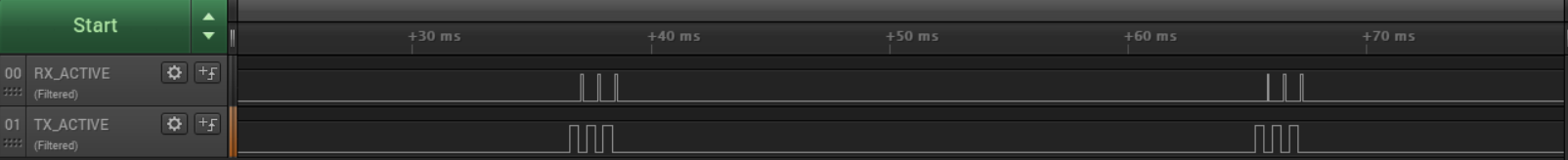
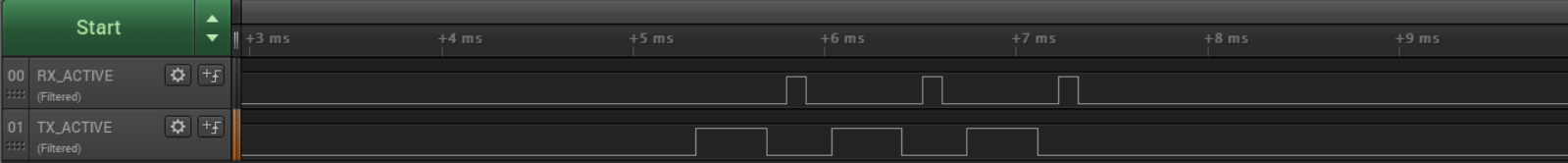
}The radio state can then be monitored using the defined pins on a logic analyzer. In this example, the radio is running a simple Bluetooth LE advertisement example. On each of the three primary advertising channels, data is first transmitted (long logic high) then the radio switches to the receive state (short logic high), which is repeated on each channel.