Example: OTA Bootloading in a Sensor-Sink Demo#
The following example walks through using OTA in a sensor-sink demo using CLI commands. The sink will be the OTA server and the sensor(s) will be the OTA client(s). The example will use sensor/sink if the context is the Connect network and OTA client/server if the context is the OTA process.
The example works with any Software Development Kit that is supported by Silicon Labs Connect, but the internal flash bootloader example is only available for 1MB (EFR32xG12) and 512kB (EFR32xG13) devices.
Create Projects#
Create either of the single image bootloader examples that are available for your devices. There is no need to modify it.
Create a connect sink application. In addition to the Bootloader Application Interface component, you only need to install the following components:
OTA Bootloader Interface
OTA Bootloader Test Common
OTA Broadcast or Unicast Bootloader Server
OTA Broadcast or Unicast Bootloader Test
This will be the OTA server project.
Create two sensor applications. The example will flash one with regular J-Link and use OTA to bootload the other. Make sure you make some difference between the two applications to distinguish between them (for example, modify the application's initialization code to print out different messages on the UART or turn on different LED). Similar to step 2, in addition to the Bootloader Application Interface component, install these components in both projects:
OTA Bootloader Interface
OTA Bootloader Test Common
OTA Broadcast or Unicast Bootloader Client
OTA Broadcast or Unicast Bootloader Test
These will be the OTA client projects.
Generate and build all four projects (bootloader, sink, two sensors).
Note: If you have only one sensor project you can save time by generating the GBL file from the unmodified application, then modifying and rebuilding it. Alternatively, you can use any other application to generate the GBL file. In this case, you cannot be certain that the application will enable OTA image distribution next time.
Note: The Connect stack uses non-volatile data storage to store various pieces of information (more generally called tokens) that the Connect stack needs to be persistent between device power cycles. These tokens support automatic network rebuilding on startup. This system can be also used by the application to store persistent data.
Note: You can find more about the GBL file format and on how to generate the GBL file in UG266: Silicon Labs Gecko Bootloader User’s Guide for GSDK 3.2 and Lower, Gecko Bootloader User’s Guide for GSDK 4.0 and Higher, or Gecko Bootloader User’s Guide for Series 3 and Higher.
Flashing Applications#
For the applications to work, you first need to flash the bootloader itself. The simplest way to flash it is to use Simplicity Commander. Make sure you use the <bootloader app name>-combined.s37 file because this is the only image with the full bootloader: Gecko Bootloader is a two-stage bootloader, which means there is a very small first stage which can update the bootloader itself (this is not demonstrated in this example). Only the -combined.s37 file includes this first stage. All other binaries are just the second stage so they will not work by themselves. For more information, see UG266: Silicon Labs Gecko Bootloader User’s Guide for GSDK 3.2 and Lower, Gecko Bootloader User’s Guide for GSDK 4.0 and Higher, or Gecko Bootloader User’s Guide for Series 3 and Higher.
Next, flash the sink and one of the sensor applications. You can use almost any method, just make sure you don't use the "bin file because it does not include address information and might overwrite the bootloader. Also, make sure you do not erase the flash memory before flashing the application.
If both the bootloader and the application are present, it should start as a usual Connect project with the available Command Line Interface (CLI).
Generating the GBL File#
Once you have the application's binaries, you need to generate the GBL file from them. Find the connect_create_gbl_image.bat or connect_create_gbl_image.sh file in the project directory depending on whether you are using Windows or UNIX. Run the file from a terminal. The GBL files will be placed in the build folder where the binaries are located.
You need to permanently define the PATH_SCMD environmental variable as a path to the Simplicity Commander root folder. With Windows, execute the following command to register this environmental variable:
setx PATH_SCMD C:\SiliconLabs\SimplicityStudio\v5\developer\adapter_packs\commanderLoading the Image to the OTA Server#
Next, you need to flash the GBL file of the other sensor to the bootloader's storage slot on the sink/OTA server as shown in the following figure.
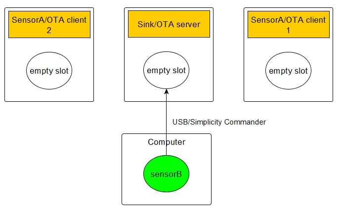
The easiest way to do this is by using the Simplicity Commander commands described in the following subsections.
Loading to SPI Flash#
To load <application image>.gbl to the SPI flash, use the following command:
commander extflash write <application image>.gblThis method is only available on Silicon Labs Development Kits. It will lock the MCU and reset the device when it is finished.
Loading Internal Flash#
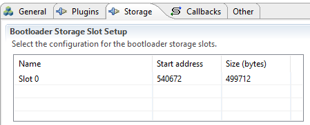
To flash to internal storage, first figure out the starting address of the slot. You can read that from the Software Components tab in the Universal Configurator by navigating to Platform > Bootloader > Bootloader Storage Slot Setup of the bootloader project. For example, for 1MB devices, it is 540672 by default as shown in the following figure.
Simplicity Commander will recognize the GBL file and you do not want to decode the address information from there (as it would flash it to address 0): Basically, you want it to handle as a binary blob. If you rename the GBL file to .bin, you get exactly that. After that, you can flash it either from the GUI (with start address) or from the command line by executing the following command:
commander flash --address 84000 <application image>.binWhere 84000 is 540642 in hexadecimal and <application image>.bin is the renamed GBL file.
For more information, see [Simplicity Commander Reference Guide]https://docs.silabs.com/simplicity-commander/latest/simplicity-commander-start/.
Preparing the Devices for Bootloading#
The next steps are CLI commands on the devices.
Preparing the Storage#
Use these commands to prepare the storage on each device.
Commands on the OTA server:
bootloader_init
bootloader_validate_imageThe second command will check the image, which should look like this (with many more dots):
Verifying image............done!
Image is valid!Commands on the OTA client:
bootloader_init
bootloader_flash_erase
The second command will erase the flash, which is required before writing it. Its output should look like this (with many more dots):
flash erase started
flash erasing slot 0 started....................................
flash erase successful!
Preparing the Network#
These commands are the usual ones to create and join to a network.
Commands on the sink:
form 0
pjoin 120The first command starts the network and the second command permits the sensor nodes to join to the network for 120 seconds.
Commands on the sensor:
join 0It is a good idea to set a slower report rate to make the CLI more usable:
set_report_period 10000Once the connection is established between the sensor and sink nodes, you should see the communication between the sink and the sensor every 10 seconds.
You also need to set a bootloader tag on the sensor:
bootloader_set_tag 0xaaYou will need the node ID of the sensor for the next steps. You can obtain the main attributes of the current state of the node by executing the info command:
Node id: 0x0001The next steps are different for unicast and broadcast OTA.
Unicast OTA#
Use the following command on the OTA server.
bootloader_unicast_set_target 0x0001This will set the destination of the OTA packets to the sensor, which has the node ID (0x0001) identified in the previous step.
With the next command, you start the OTA distribution itself as shown in the following figure.
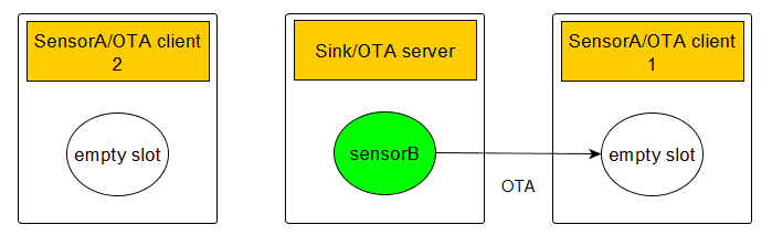
bootloader_unicast_distribute <size> 0xaaWhere <size> is the size of the GBL image in bytes and 0xaa is the tag you set up previously on the OTA client.
This starts the OTA image distribution process. You should see get segment lines on the OTA server (that is, reading segments from flash memory) and incoming segment lines on the OTA client. It should end with image distribution completed, 0x00 on the server side and Image download COMPLETED tag=0xAA size=\<size\> on the client side.
At this point, bootloader_validate_image should return with valid on the client as well.
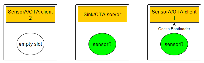
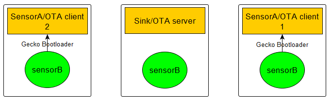
Next, you are going to request bootloading as shown in the following figure.
To do that, execute the following command on the OTA server:
bootloader_unicast_request_bootload 1000 0xaaWhere 1000 is a timeout in ms and 0xaa is the tag again.
Unicast Download Resume Feature#
Starting with Flex SDK version 2.6 the OTA download feature supports resuming the download from the segment at which the transmission was interrupted. To test this feature, reset the OTA server during download (by hardware reset pin or issuing the reset command in the CLI. When the reset cycle has completed, issue the same commands on the server as were issued on the first attempt:
bootloader_init
bootloader_unicast_set_target 0x0001
`bootloader_unicast_distribute <size> 0xaa`The download should start from the point where it was interrupted. There is no limit to the number of times the interrupt and resume can be repeated. If the tag has been changed or the flash has been erased on the OTA client, the download will start from the beginning (that is, the whole image will be downloaded).
Broadcast OTA#
First, you set up the target list on the OTA server. This is the list of the client's node IDs. This is used for missing segment request and bootload request messages. The maximum number of clients is limited in the broadcast plugin to 50.
The following command on the OTA server sets the node ID of the OTA client at index 0 to 0x0001:
bootloader_broadcast_set_target 0 0x0001You can set up multiple targets with the same command by incrementing the index.
With the next command, you are starting the OTA distribution itself as shown in the following figure.
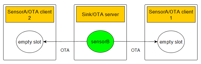
bootloader_broadcast_distribute <size> 0xaa 1Where <size> is the size of the GBL image in bytes and 0xaa is the tag you set up previously on the OTA client and 1 is number of clients you set up using set-target.
This starts the OTA image distribution process. You should see get segment lines on the OTA server (that is, reading segments from flash memory) and incoming segment lines on the OTA client. It should end with image distribution completed, 0x00 on the server side and Image download COMPLETED tag=0xAA size=<size> on the client side.
At this point, bootloader_validate_image should return with valid on the client(s) as well.
Next, you are going to request bootloading as shown in the following figure.
To do that, execute the following command on the OTA server:
bootloader_broadcast_request_bootload 1000 0xaa 1Where 1000 is a timeout in ms and the last two parameters are the same as above for distribute.
Bootloading Finished#
Both unicast and broadcast bootload request should immediately return with bootload request completed. After the timeout, you should see the bootloading of the OTA client. After bootloading, the sensor should join again because the network information is stored in NVM, but this time you should see the differences you set up for the OTA image.