WLAN - BLE Extended Advertising CoEx App#
1. Purpose / Scope#
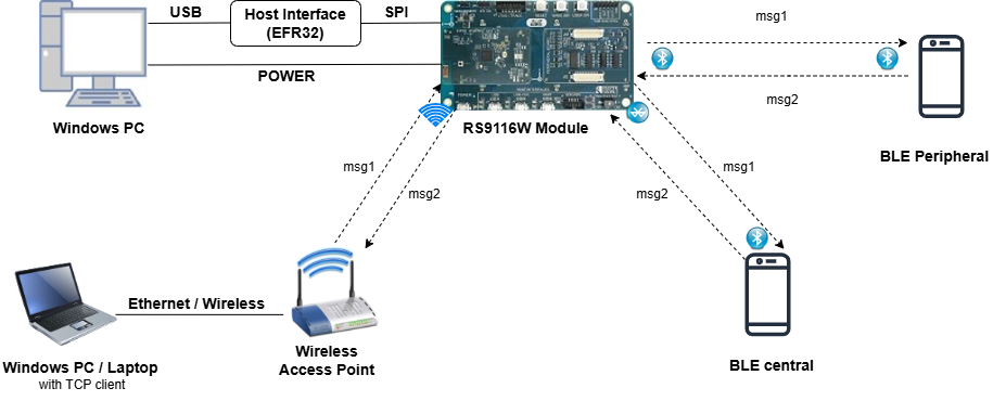
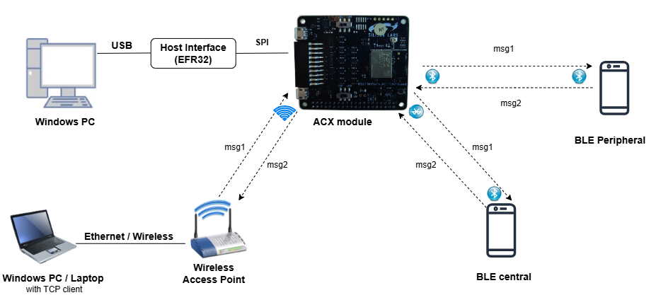
This application demonstrates how to configure RS9116W EVK as both Extended Advertiser(Peripheral) with two advertising sets supported and Extended Scanner(Central). It supports multiple connections (one central + one peripheral), WLAN Station Connection along with SMP feature and data transfer.
2. Prerequisites / Setup Requirements#
Before running the application, you need to setup the following things.
2.1 Hardware Requirements#
Windows PC with Host interface(UART/ SPI).
Silicon Labs RS9116 Wi-Fi Evaluation Kit
Host MCU Eval Kit. This example has been tested with:
Silicon Labs WSTK + EFR32MG21
BLE peripheral device with AE support.
BLE central device with AE support.
Wi-Fi Access point with a connection to the internet.
Windows PC2 (Remote PC) if TCP data needs to be transffered on Wi-Fi.


2.2 Software Requirements#
Embedded Development Environment
For Silicon Labs EFx32, use the latest version of Simplicity Studio
Download and install the Silicon Labs Simplicity Connect App (formerly EFR Connect App) or other BLE Central/Peripheral app in the Android/iOS smart phones for testing BLE applications. You can also use their choice of BLE apps available in Android/iOS smart phones (which support AE).
3. Application Build Environment#
The Application is built and executed on following Host platforms: WSTK + EFR32MG21
3.1 Host Interface#
By default, the application is configured to use the SPI bus for interfacing between Host platforms and the RS9116W EVK.
The SAPI driver provides APIs to enable other host interfaces if SPI is not suitable for your needs.
Refer to "Connect the RS9116W EVK to the host MCU development board" section in the following link for SPI connections Refer Connect the RS9116W EVK to the host MCU development board
3.2 Project Configuration#
The Application is provided with the project folder containing Simplicity Studio project files.
Simplicity Studio
The Simplicity Studio project is used to evaluate the application on EFR32MG21.
Project path:
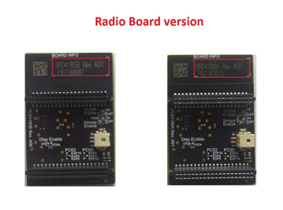
If the Radio Board is BRD4180A or BRD4181A, then access the path
<SDK>/examples/snippets/ble/wlan_ble_ae_coex_app/projects/wlan_ble_ae_coex_app-brd4180a-mg21.slsprojIf the Radio Board is BRD4180B or BRD4181B, then access the path
<SDK>/examples/snippets/ble/wlan_ble_ae_coex_app/projects/wlan_ble_ae_coex_app-brd4180b-mg21.slsprojUser can find the Radio Board version as given below

3.3 RTOS Support#
This application supports only RTOS configuration. By default, the application project files (Simplicity studio) are provided with OS environment in the SDK.
4. Application Configuration Parameters#
The application can be configured to suit your requirements and development environment. Read through the following sections and make any changes needed.
4.1 Open ble_config.h file and update/modify following macros,
4.1.1 User must update the below parameters
Configure the below macros to enable extended advertsing and scanning by default respectively
       #define ADV_ENABLED_DEFAULT    1
       #define SCAN_ENABLED_DEFAULT   1
Set the below macro to enable second advertising set
#define ADV_SET2 1Configure the below macros to set the number of peripheral and central connections that can be made
       #define RSI_BLE_MAX_NBR_SLAVES    1
       #define RSI_BLE_MAX_NBR_MASTERS   1
RSI_REMOTE_DEVICE_NAME1 refers address of the remote device(AE peripheral) to connect
#define RSI_REMOTE_DEVICE_NAME1 AEdevice1Configure following macros to enable secure connection for central and peripheral respectively:
       #define SMP_ENABLE_M1    1
       #define SMP_ENABLE_S1    1
Enable the following macros to receive the "GATT Notifications" from the remote devices
       #define RX_NOTIFICATIONS_FROM_M1    1
       #define RX_NOTIFICATIONS_FROM_S1    1
Note: The maximum number of peripheral connections support, and the maximum number of central connections support is one for both.
Power save configuration
By default, the application is configured with power save enable feature:
#define ENABLE_POWER_SAVE 1
To disable power save, modify the following configuration:
#define ENABLE_POWER_SAVE 0
For Powersave functionality with NCP expansion (ACX) board
Note:For using power save functionality with NCP expansion (ACX) board, the
EXP_BOARD = 1pre-processor symbol should be added to the list of defined symbols in the pre-processor menu of project settings."
> - Open the project in Simplicity Studio
> - Right click on the project and choose 'Properties'
> - Go to 'C/C++ Build' | 'Settings' | 'GNU ARM C Compiler' | 'Pre-processor' and add the macro `EXP_BOARD = 1`
> - Select 'Apply' and 'OK' to save the settings

To add the macro
1.Click Add to Pre-processor defines symbol
2.Add macro EXP_BOARD and assign it to 1
3.Click OK
4.Click "Apply and Close" 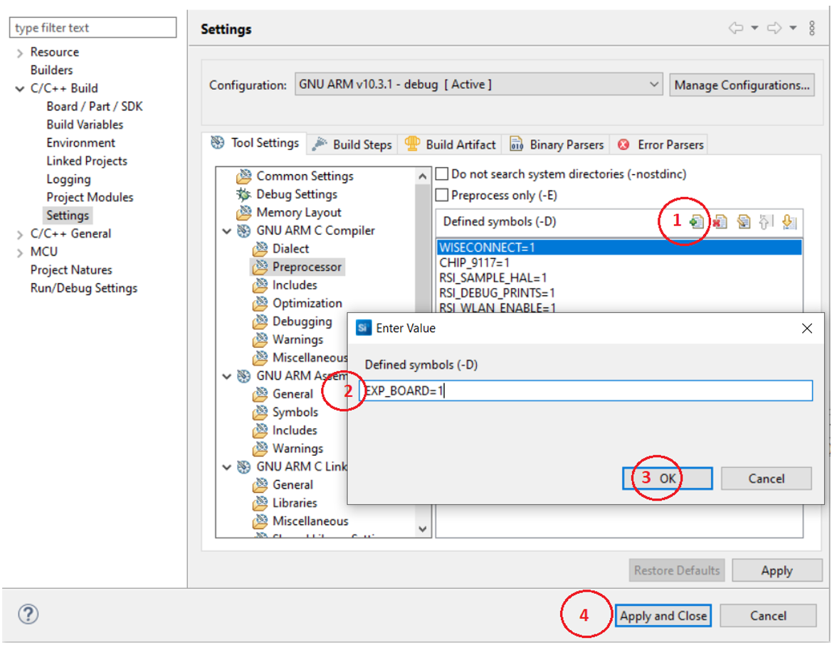

4.1.2 Following are the desired parameters. You can also modify the parameters as per their needs and requirements.
4.1.2.1 Extended Advertising parameters
The length of the advertising data needs to be filled in the following macro
#define BLE_AE_ADV_DATA_LEN 0x19Below mentioned macro needs to be populated with data
#define BLE_AE_ADV_DATA "AE_PERIPHERAL_DATA_1"The Extended advertising handle for set 1 and 2 can be set with the following macros respectively
#define BLE_AE_ADV_HNDL_SET_1          0x00
#define BLE_AE_ADV_HNDL_SET_2          0x01
The minimum advertising interval for set1 and set2 can be configured using the following macros
#define BLE_AE_ADV_INT_MIN_SET_1       0x664
#define BLE_AE_ADV_INT_MIN_SET_2       0x664
The maximum advertising interval for set1 and set2 can be configured with the following macros respectively
#define BLE_AE_ADV_INT_MAX_SET_1       0x664
#define BLE_AE_ADV_INT_MAX_SET_2       0x664
The Extended advertising channel map for set1 and set2 can be configured with the following macros respectively
#define BLE_AE_ADV_CHANNEL_MAP_SET_1   0x07
#define BLE_AE_ADV_CHANNEL_MAP_SET_2   0x07
The Extended advertising filter policy for set1 and set2 can be configured with the following macros respectively
#define BLE_AE_ADV_FILTER_POLICY_SET_1 0x00
#define BLE_AE_ADV_FILTER_POLICY_SET_2 0x00
The Extended advertising TX Power for set1 and set2 can be configured with the following macros respectively
#define BLE_AE_ADV_TX_PWR_SET_1        0x00
#define BLE_AE_ADV_TX_PWR_SET_2        0x06
The primary advertising phy for set1 and set2 can be configured with the following macros respectively
#define BLE_AE_PRIMARY_ADV_PHY_SET_1   0x01
#define BLE_AE_PRIMARY_ADV_PHY_SET_2   0x03
The Extended advertising max skip for set1 and set2 can be configured with the following macros respectively
#define BLE_AE_SEC_ADV_MAX_SKIP_SET_1  0x00
#define BLE_AE_SEC_ADV_MAX_SKIP_SET_2  0x00
The secondary advertising phy for set1 and set2 can be configured with the following macros respectively
#define BLE_AE_SECONDARY_ADV_PHY_SET_1 0x01
#define BLE_AE_SECONDARY_ADV_PHY_SET_2 0x03
The Extended advertising SID for set1 and set2 can be configured with the following macros respectively
#define BLE_AE_ADV_SID_SET_1           0x00
#define BLE_AE_ADV_SID_SET_2           0x01
The Extended advertising scan request notification enable for set1 and set2 can be configured with the following macros respectively
#define BLE_AE_SCAN_REQ_NOTIF_EN_SET_1 0x01
#define BLE_AE_SCAN_REQ_NOTIF_EN_SET_2 0x01
The Extended advertising event properties for set1 and set2 can be configured with the following macros respectively
#define BLE_AE_ADV_EVNT_PROP_SET_1     (BLE_CONNECTABLE_ADV)
#define BLE_AE_ADV_EVNT_PROP_SET_2     0x00
The Extended advertising duration for set1 and set2 can be configured with the following macros respectively
#define BLE_AE_ADV_DUR_SET_1           0x00
#define BLE_AE_ADV_DUR_SET_2           0x00
The maximum extended advertising events for set1 and set2 can be configured with the following macros respectively
#define BLE_AE_ADV_MAX_AE_EVENTS_SET_1 0x00
#define BLE_AE_ADV_MAX_AE_EVENTS_SET_2 0x00
4.1.2.2 Extended scan parameters
Extended scanning filter type can be set with the following macro
#define BLE_AE_SCAN_FILTER_TYPE SCAN_FILTER_TYPE_ALLThe scan type for primary phy can be set using following macro
#define PRI_PHY_BLE_AE_SCAN_TYPE SCAN_TYPE_ACTIVEThe scan type for secondary phy can be set using following macro
#define SEC_PHY_BLE_AE_SCAN_TYPE SCAN_TYPE_ACTIVEThe primary phy extended scan interval can be set using following macro
#define PRI_PHY_LE_AE_SCAN_INTERVAL 0x14A0The primary phy extended scan window can be set using following macro
#define PRI_PHY_LE_AE_SCAN_WINDOW 0x14A0The secondary phy extended scan interval can be set using following macro
#define SEC_PHY_LE_AE_SCAN_INTERVAL 0x14A0The secondary phy extended scan window can be set using following macro
#define SEC_PHY_LE_AE_SCAN_WINDOW 0x14A0Extended scanning filter duplicates can be set using following macro
#define BLE_AE_SCAN_ENABLE_FILTER_DUP 0x00Extended scan duration can be set using following macro
#define BLE_AE_SCAN_DUR 0x00Extended scan period can be set using following macro
#define BLE_AE_SCAN_PERIOD 0x00Following are the non-configurable macros in the application.
The event properties bits:
#define BLE_CONNECTABLE_ADV        (1 << 0)
#define BLE_SCANNABLE_ADV          (1 << 1)
#define BLE_LOW_DUTY_DIR_CONN_ADV  (1 << 2)
#define BLE_HIGH_DUTY_DIR_CONN_ADV (1 << 3)
#define BLE_LEGACY_ADV             (1 << 4)
#define BLE_ANONYMOUS_ADV          (1 << 5)
#define BLE_TX_WR_ADV              (1 << 6)
Global buffer length:
#define GLOBAL_BUFF_LEN 15000Phy rate bits:
#define PHY_1M       BIT(0)
#define PHY_2M       BIT(1)
#define PHY_LE_CODED BIT(2)
#define RSI_BLE_PWR_INX 30
#define RSI_BLE_PWR_SAVE_OPTIONS 0
#define BLE_DISABLE_DUTY_CYCLING 0
#define BLE_DUTY_CYCLING 1
#define BLR_DUTY_CYCLING 2
#define BLE_4X_PWR_SAVE_MODE 4Opermode command parameters
	 #define RSI_FEATURE_BIT_MAP                            FEAT_SECURITY_OPEN
	 #define RSI_TCP_IP_BYPASS                              RSI_DISABLE
	 #define RSI_TCP_IP_FEATURE_BIT_MAP                     TCP_IP_FEAT_DHCPV4_CLIENT
	 #define RSI_CUSTOM_FEATURE_BIT_MAP                     FEAT_CUSTOM_FEAT_EXTENTION_VALID
	 #define RSI_EXT_CUSTOM_FEATURE_BIT_MAP                 (EXT_FEAT_LOW_POWER_MODE | EXT_FEAT_XTAL_CLK_ENABLE)
	 #define RSI_EXT_TCPIP_FEATURE_BITMAP 			(EXT_TCP_IP_WINDOW_DIV | EXT_TCP_IP_WAIT_FOR_SOCKET_CLOSE)
Note: ble_config.h file is already set with desired configuration in the respective example folder, you need not change for each example.
4.2 Open rsi_wlan_tcp_server_app.c file and update/modify following macros,
SSID refers to the name of the Access point.
#define SSID "YOUR_AP_SSID"PSK refers to the Password of the Access point.
#define PSK "YOUR_AP_PASSWORD"SECURITY_TYPE refers to the security type of the Access Point either OPEN/WPA_2
#define SECURITY_TYPE RSI_WPA25. Testing the Application#
User has to follow the below steps for the successful execution of the application.
5.1 Loading the RS9116W Firmware#
Refer Getting started with PC to load the firmware into RS9116W EVK. The firmware binary is located in <SDK>/firmware/
5.2 Building the Application on the Host Platform#
Refer EFx32 Getting Started
Import the project from
<SDK>/examples/snippets/ble/wlan_ble_ae_coex_app/projectsSelect the appropriate .slsproj as per Radio Board type mentioned in Section 3.3
Compile and flash the project in to Host MCU
Debug the project
Check for the RESET pin:
If RESET pin is connected from EFX32 to RS9116W EVK, then you need not press the RESET button on RS9116W EVK before free run
If RESET pin is not connected from EFX32 to RS9116W EVK, then you need to press the RESET button on RS9116W EVK before free run
Free run the project
Successful build output are shown further.
6. Program the device#
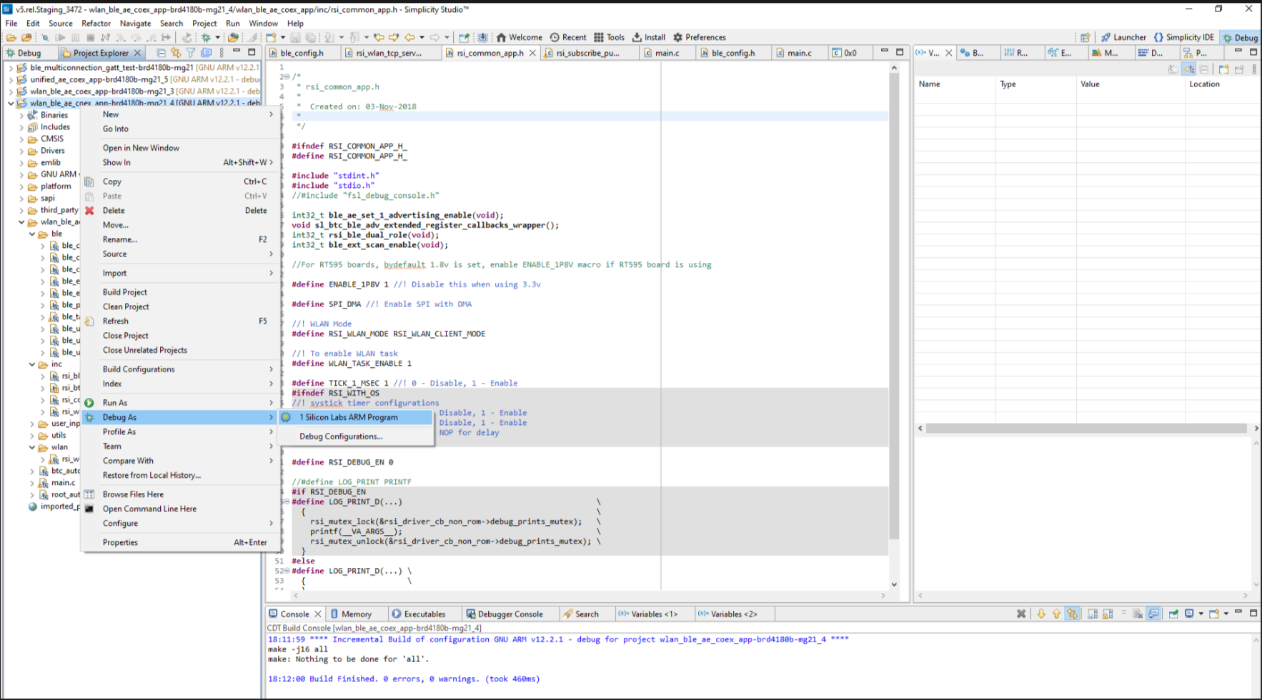
Once the build was successfull, right click on project, and click on Debug As->Silicon Labs ARM Program as shown in the following image.

6.1 Running the RS9116W Application#
6.1.1 Steps to be followed to verify BLE AE Unified CoEx App#
Set all the configurations necessary refering to section 4.
The RS9116W device, with its default configuration parameters, is set up for two extended advertising sets and extended scanning. Its advertising functionality validates with any remote device supporting the AE feature. The following image illustrates the RS9116W device's extended advertising sets in the Si Connect app
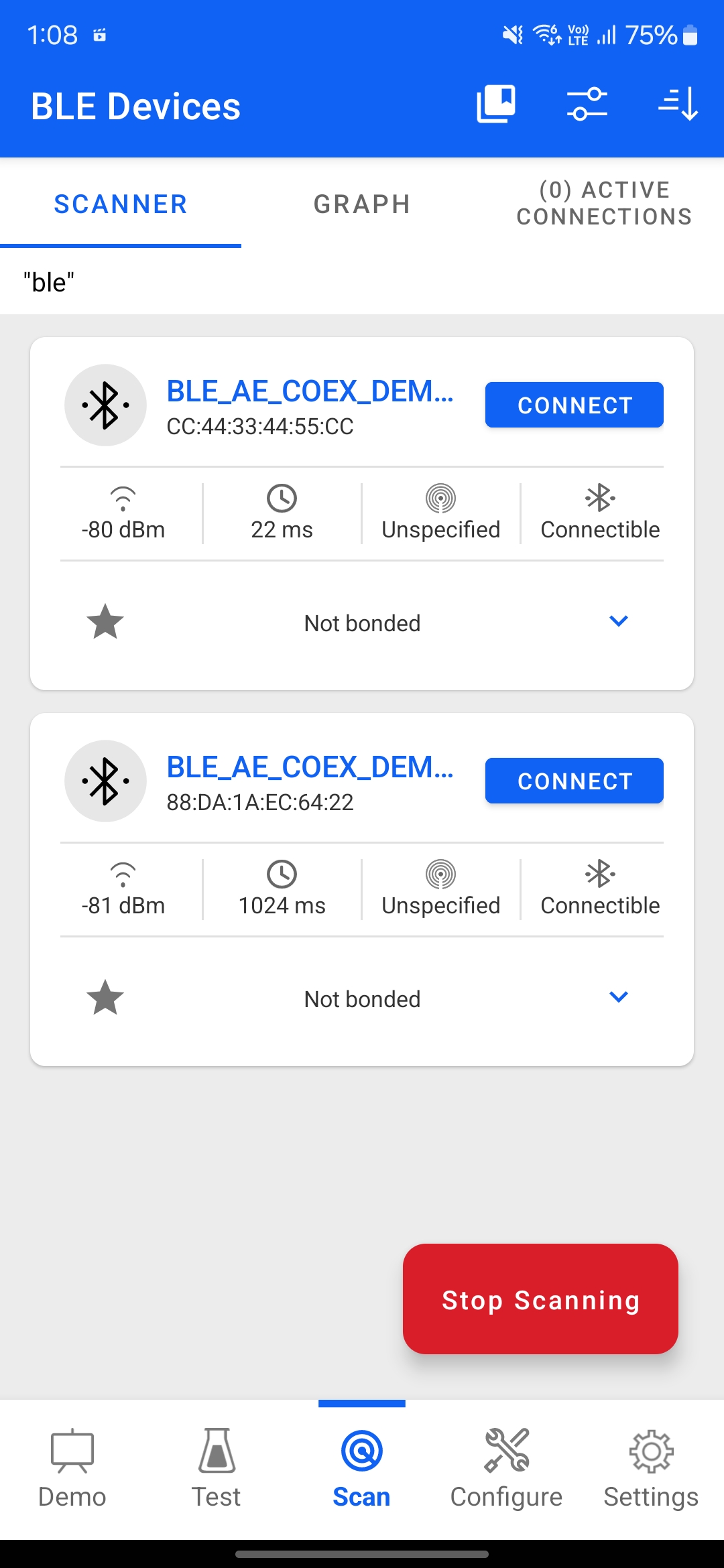

To make remote central connection , scan from any BLE scanner search for the device (if no random address is set it advertises with the public address).
As shown in step 2, to establish the connection, click on the "CONNECT" option of the device for the required advertising set.
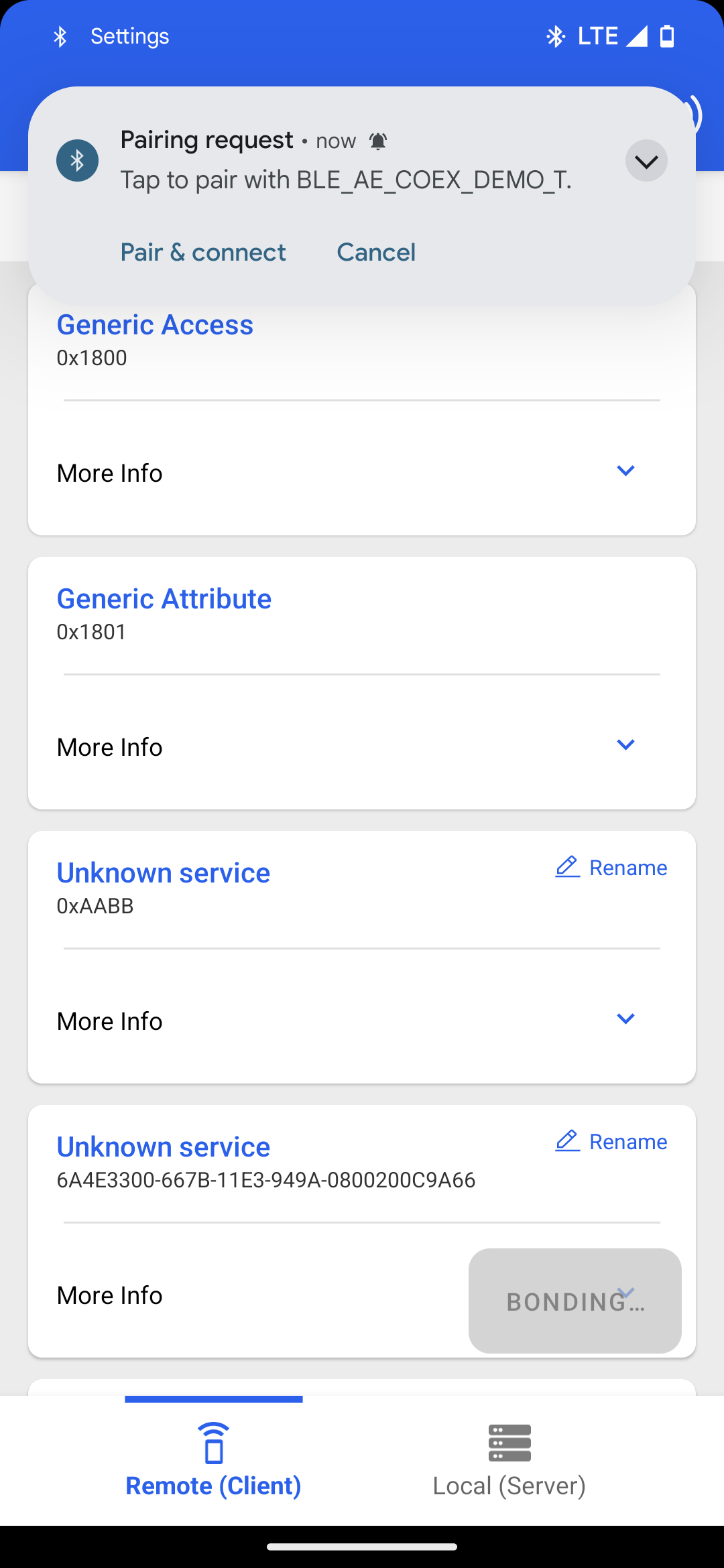
Once the physical level connection is established, and if SMP is enabled, the application initiates the SMP process, as shown in the following images.
The pairing procedure using the app is as follows: Select the "Pair and Connect" option.
Click on the "Pair and connect" option

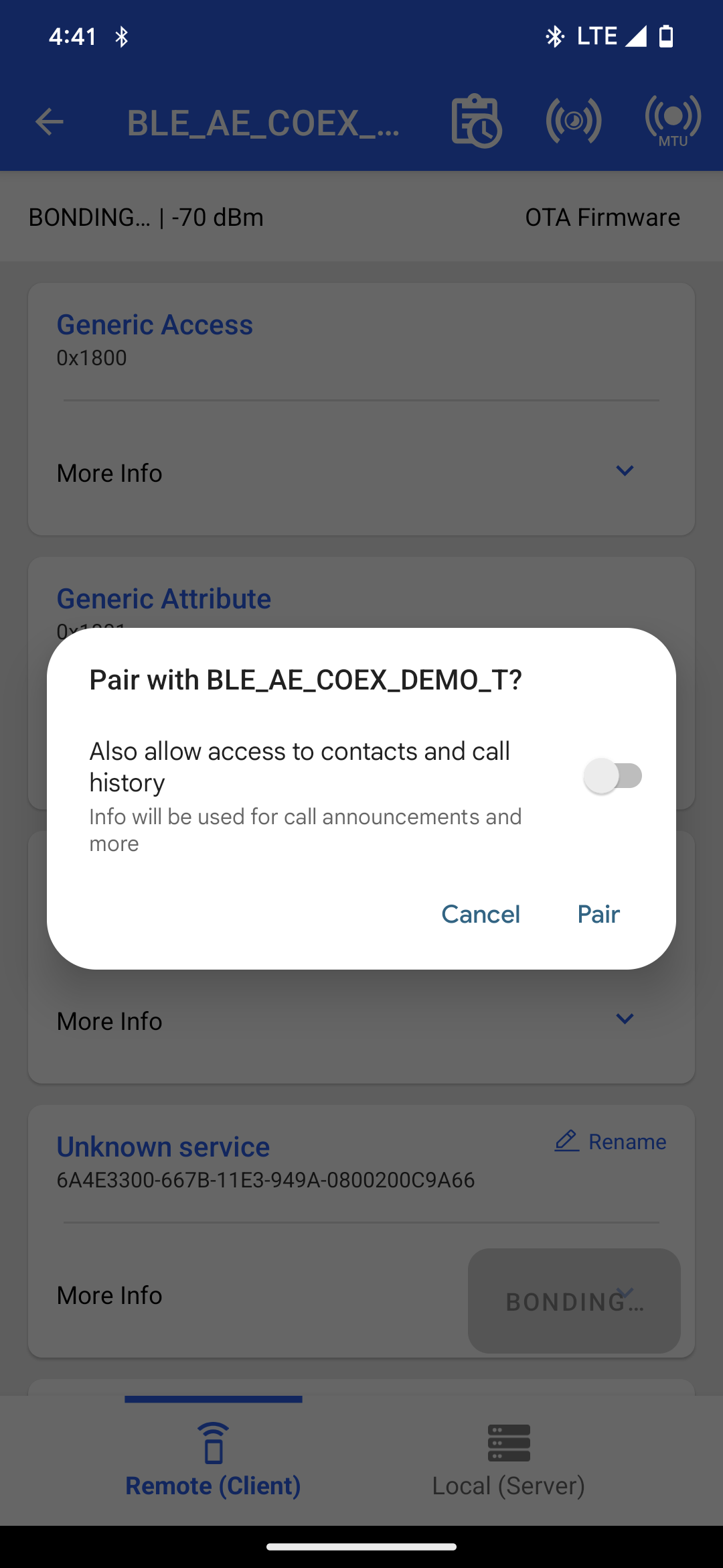

Enter the passkey displayed in the serial terminal, as shown in the following images.
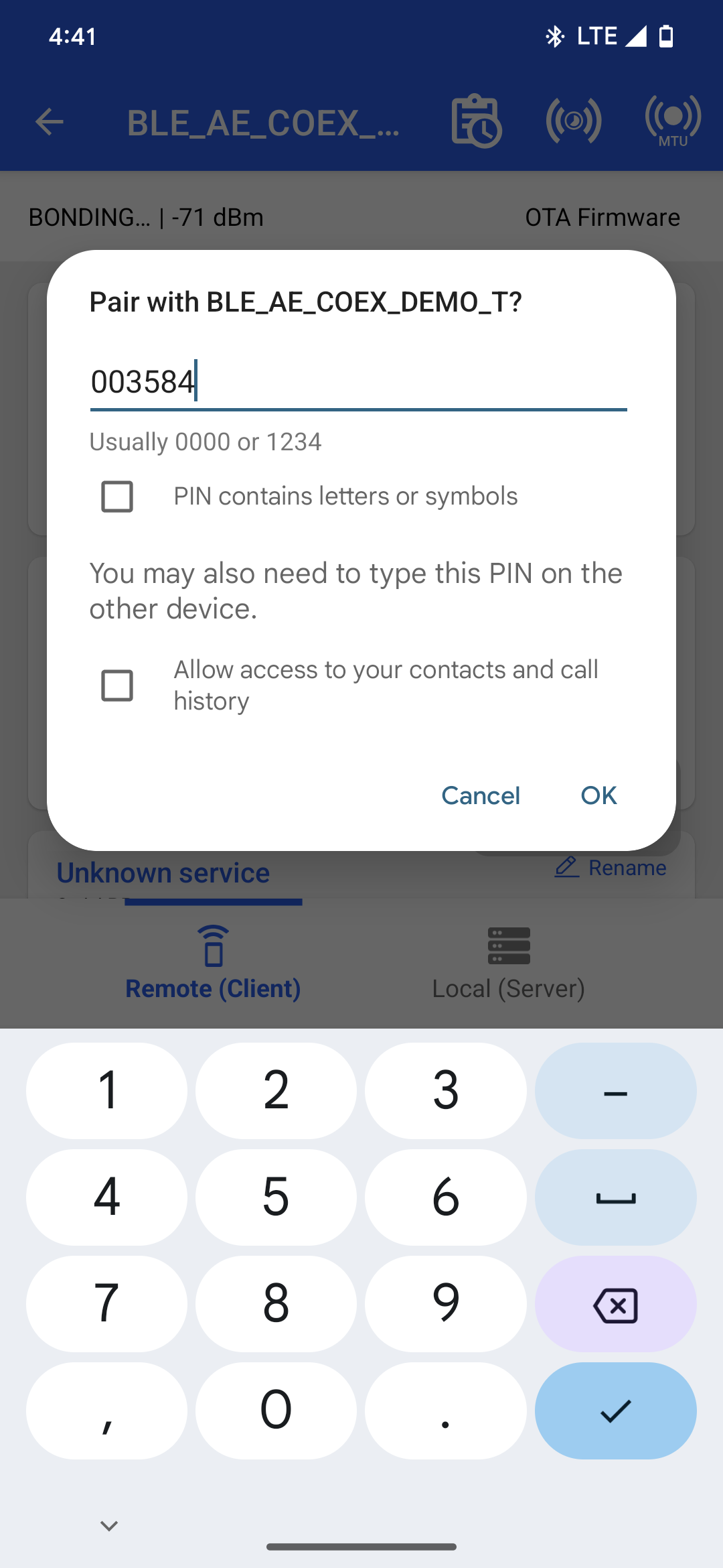

Once the SMP pairing process is successful, the connection status is displayed as follows :
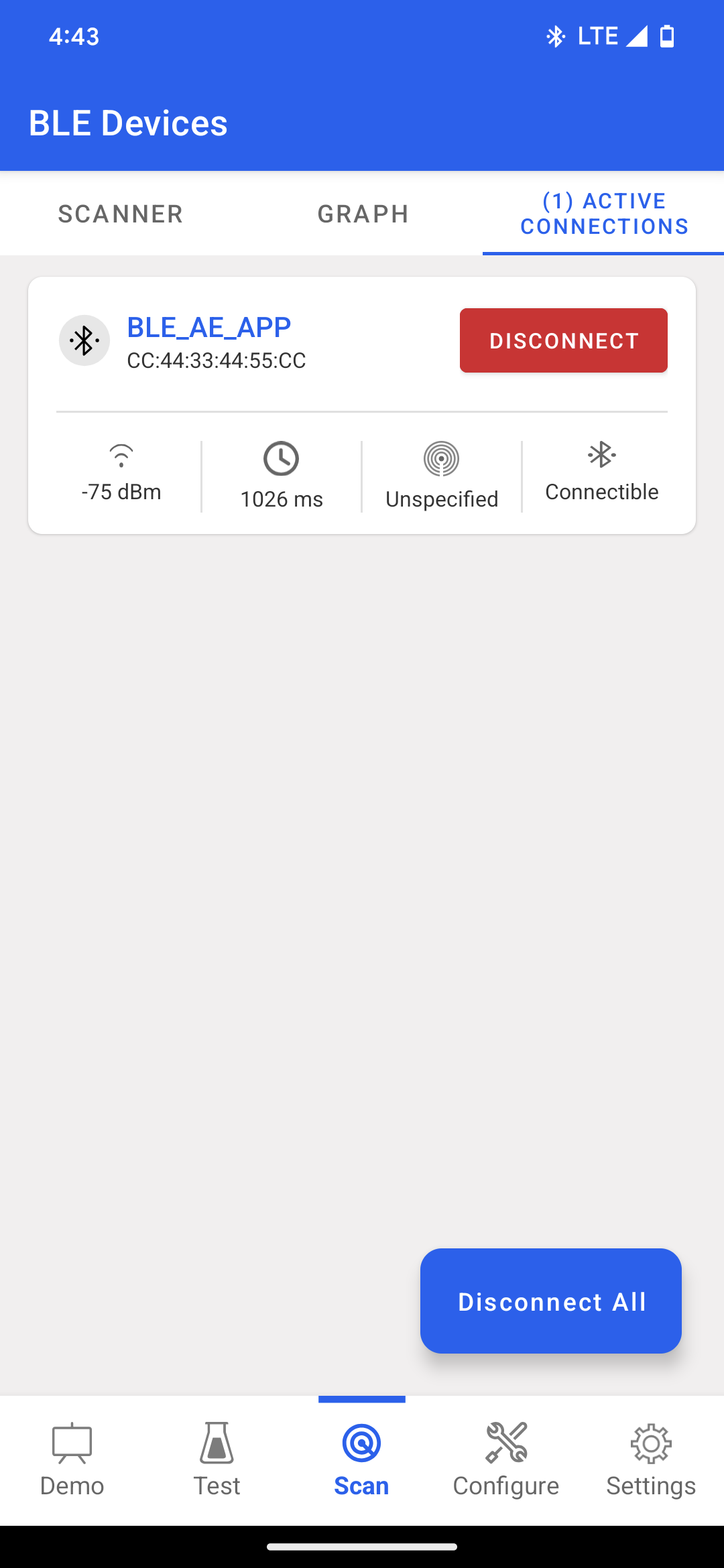

If extended scanning is enabled, the RS9116W device scans for the advertising devices using the configured scan parameters.
To make a remote peripheral connection, advertise the remote device with the specific name defined in the RSI_REMOTE_DEVICE_NAME1 macro. If SMP is enabled for this connection, the bonding process is initiated. Here in the example of heart rate service and advertise the device clicking on create new button and configuring required parameters in the advertiser.
Note: Refer to " Create a New Advertisement Set " for creating the advertising set in the Simplicity Connect mobile App (formerly EFR Connect App).
Refer Create a New Advertisement Set . Add required services say for example heart rate service and advertise the device clicking on create new button and configuring required parameters in the advertiser.
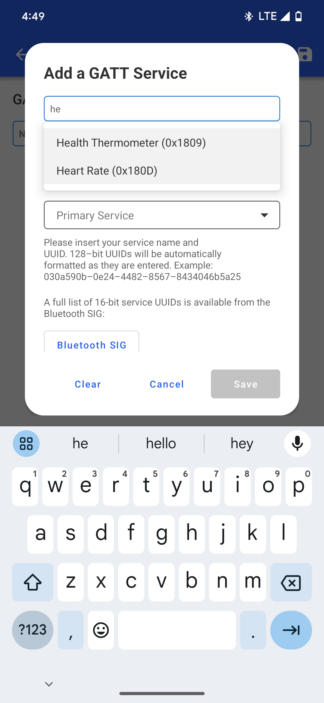

Select the "Notify" property to enable notifications for continuous data transfer from the RS9116W device.
Following image shows how to enable TX notifications from DUT after connection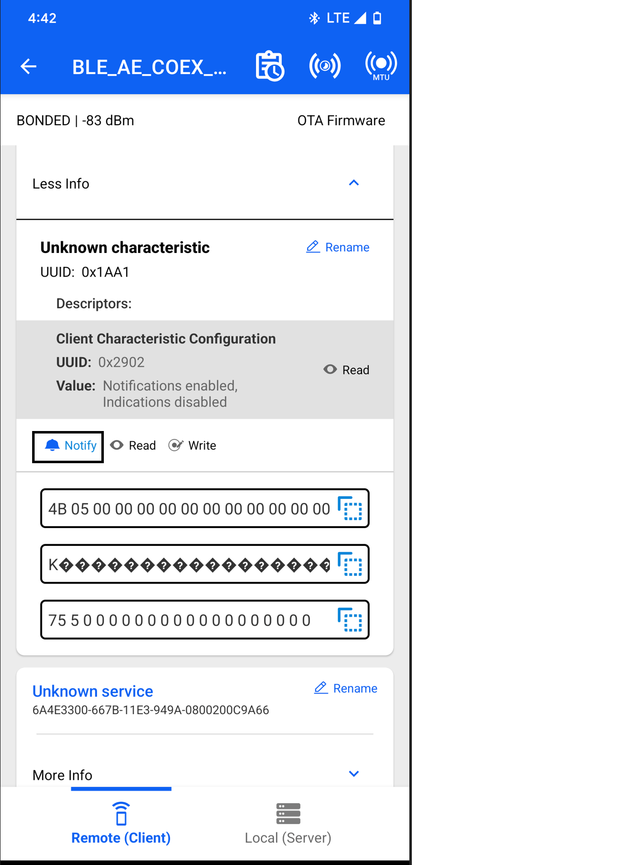

To enable Wi-Fi TCP data transfer, user needs to set the macro TCP_DATA_TEST_CODE = 1 in rsi_wlan_tcp_server_app.c
Run TCP client on another PC (preferably linux) and issue the following command using command prompt in iperf application :
  TCP client command.
  iperf -c <IPAddr> -p <portnumber> -i <interval between reports (seconds)> -t <time (in sec)>
  TCP server command.
  iperf -s -p <portnumber> -i <interval between reports (seconds)>
  for example :
    1. To run TCP_RX on our module for 10 mins with the remote client having IP_ADDR = 192.168.10.100 - Run the following command on the remote client.
       iperf -c 192.168.10.100 -p 5003 -i 1 -t 600
    2. To run TCP_TX on our module with the remote client having IP_ADDR = 192.168.10.100 - Run the below command on the remote client.
       iperf -s -p 5003 -i 1
7. Observing the output prints on serial terminal#
Prints can see following in any Console terminal
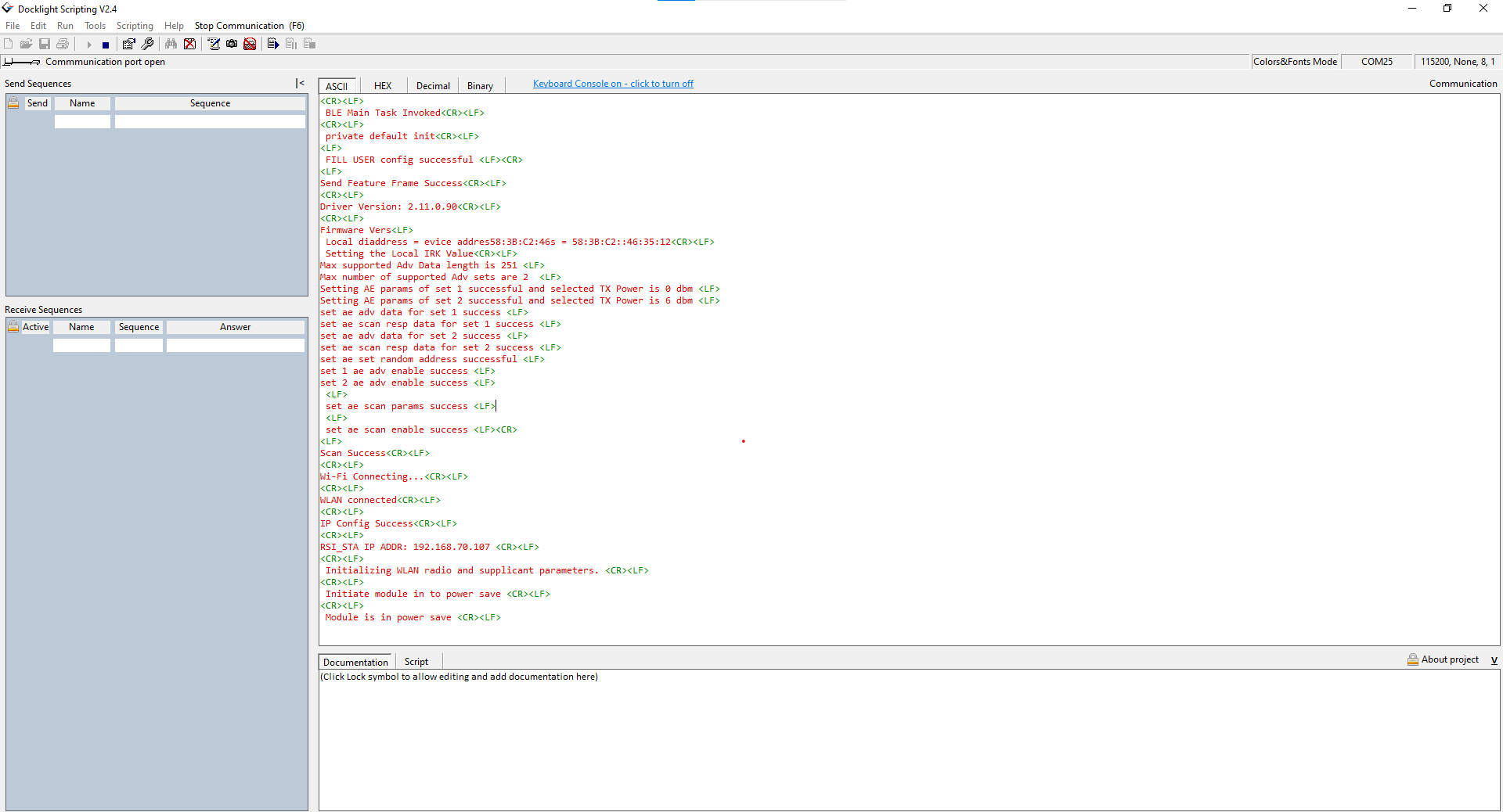

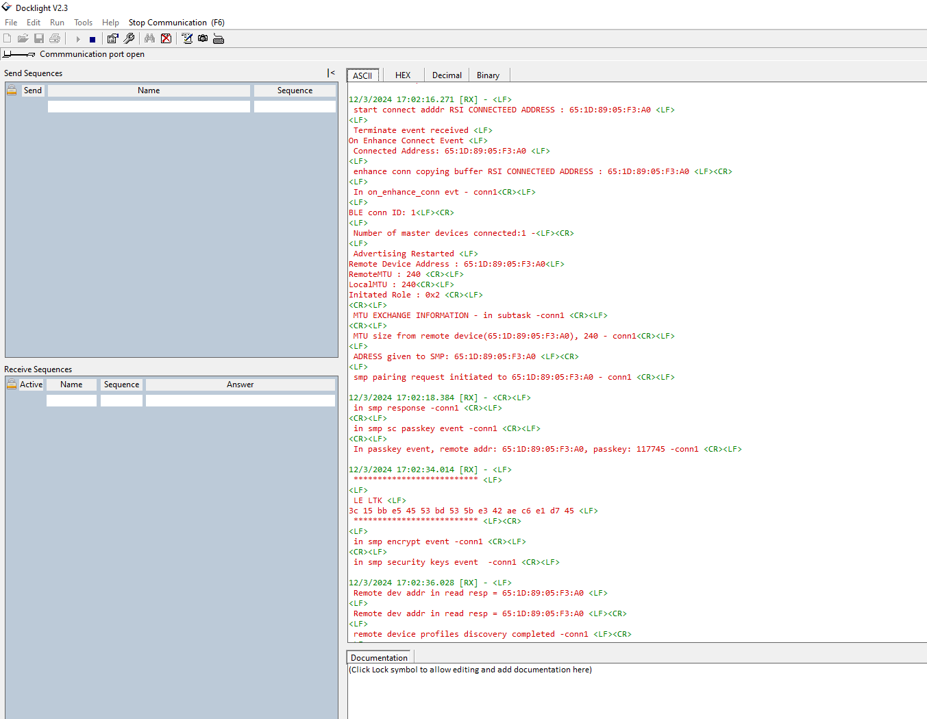

Note: Wi-Fi TCP data transfer can be enabled using the macro (TCP_DATA_TEST_CODE) in this application. Data stalls occurs during TCP data transfer when the module is in power-saving mode.
