Devices Menu
When you click the Devices menu, the Devices page displays a list of your connected devices. You can expand each device to view its associated components by clicking the arrow to the left of the device name. When expanded, the arrow points downward.
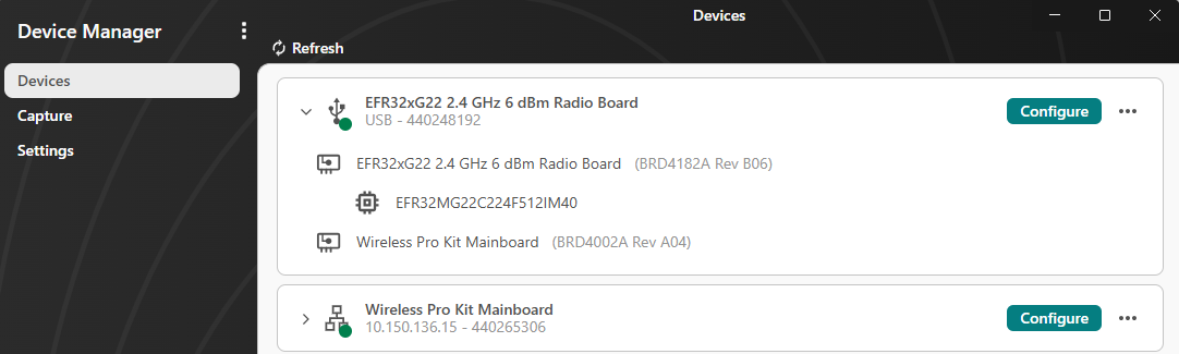
To refresh the device list, click Refresh at the top of the page.
Each connected device includes a Configure button and an ellipsis on the right. Click Configure to open the Device Overview page, where you can configure device settings. If you click the ellipsis, a shortcut menu appears with the following options:
Detailed Overview: Opens the Device Overview page
Flash Target: Opens the Flash Target Application page
Update Adapter: Opens the Update Adapter page
Set Nickname: Opens the Device Hardware page
One or more Open <name of terminal> options, depending on how many terminals are connected to your device. Each option opens the associated terminal page.
To return, click < Devices in the upper-left corner of your screen.
Device Overview Page#
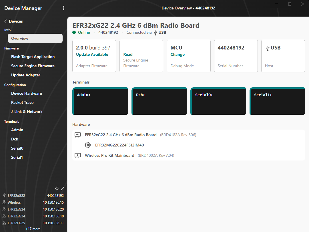
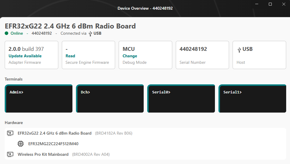
On the Device Overview page, you can view general information about the selected device and access configuration settings.
When this page is open, the following options appear on the left under the Devices menu.
Info Menu Options
Click Overview to display the Device Overview page, which shows:
The name of the selected device
The device status (for example, online)
The device serial number
How the device is connected (for example, USB)
A row of tiles showing information about:
Adapter firmware
Secure firmware
Connectivity firmware (917 chip family only)
Debug mode
Device serial number
Host
Some tiles include Read or Change links in blue. Select these links to view or update the information.
Note: The secure engine and connectivity firmware information is not shown by default. To view them, click Read.
Available terminals for the device. Hover over a terminal name to see its status, or click a terminal name to open it.
A list of the hardware components associated with the device
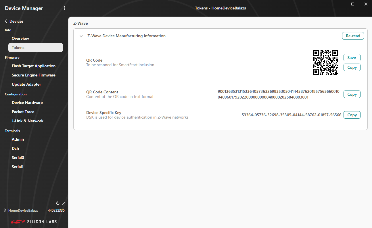
Click Tokens to display the Tokens page, which shows the token information used by the device (for example, a Z-Wave token).
Firmware Menu Options
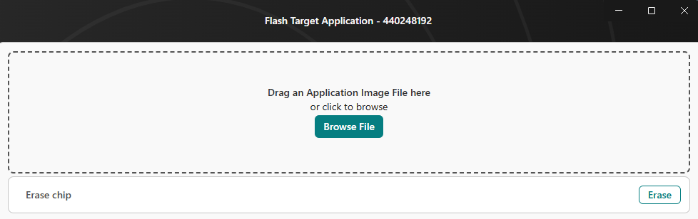
Flash Target Application#
Click Flash Target Application to display the Flash Target Application page, where you can flash and erase your device. The adapter serial number is displayed to the right of the page title.
To flash the target application, drag and drop an application image file, or browse to select a file.
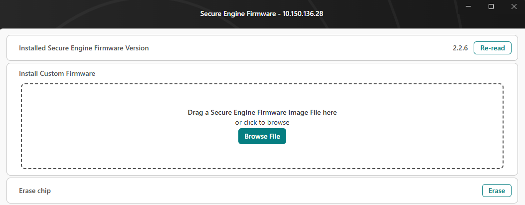
Secure Engine Firmware#
Click Secure Engine Firmware to open the Secure Engine Firmware page, where you can flash the secure engine firmware. The adapter serial number is displayed to the right of the page title, and the firmware version appears below the title.
In the Install Custom Firmware section, you can install custom firmware by dragging and dropping a file, or by browsing for a secure engine firmware image file.
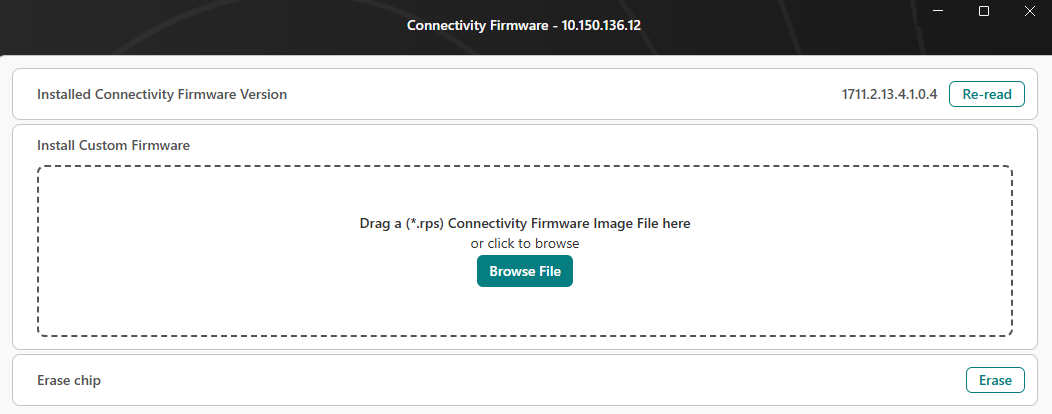
Connectivity Firmware (Only 917 chip family)#
Click Connectivity Firmware to open the Connectivity Firmware page, where you can flash the connectivity firmware. The adapter serial number appears to the right of the page title, and the firmware version appears below the title.
In the Install Custom Firmware section, you can install custom firmware by dragging and dropping a file, or by browsing for a custom connectivity firmware image file.
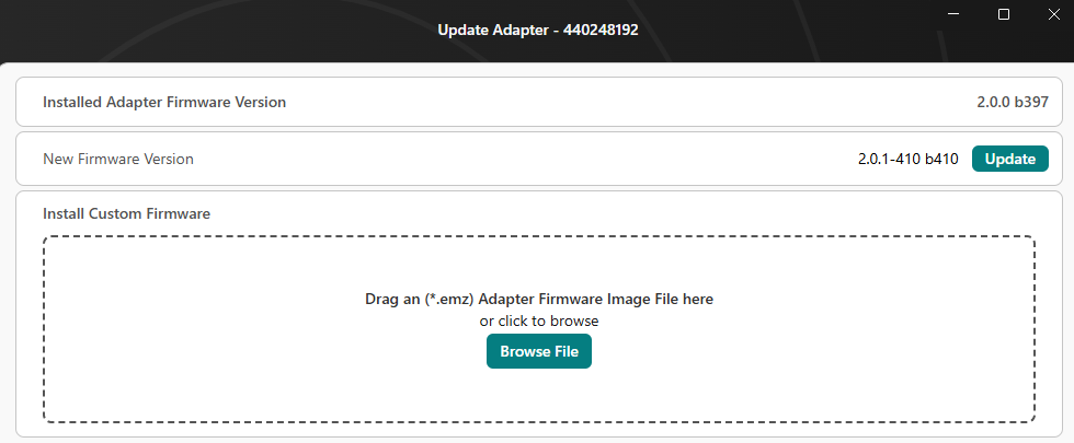
Update Adapter#
Click Update Adapter to display the Update Adapter page, where you can update the adapter firmware. The adapter serial number appears to the right of the page title, and the current adapter firmware version displays below the title.
If a newer firmware version is available, an Update button appears.
You can also install custom firmware by dragging and dropping, or by browsing for a custom adapter firmware image file using the Install Custom Firmware section.
Configuration Menu Options
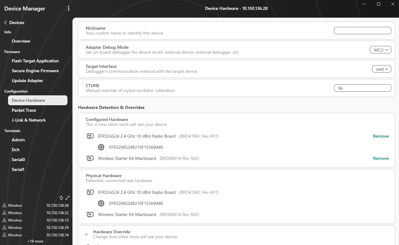
Device Hardware#
Click Device Hardware to access the following options:
Nickname: Enter a unique name for your device in the field on the right.
Adapter Debug Mode: Select the adapter connection mode from the dropdown list on the right.
MCU: The debug adapter is connected to the target part on a connected radio board for main boards or the built-in target part for other development kits.
OUT: The debug adapter connects to an offboard target part through the debug connectors.
IN: The target part on a connected radio board for main boards or the built-in target part for other development kits are connected to the debug connectors, so a connection can be made from a different debug adapter. Mainly used to simulate a connection to a custom board.
MINI: Only available on the Wireless Pro Kit (WPK - BRD4002). Similar to OUT mode, but uses the Mini Simplicity Connector on the board instead of the debug connectors.
OFF: Turns off all connections to target parts. Not useful for development. The debug adapter goes into this mode if it is in bootloader mode. If you cannot change the debug mode from OFF, then you must update the debug adapter firmware.
Target Interface: Select the interface connection mode from the dropdown list on the right.
CTUNE: Allows manual override of the crystal oscillator calibration process.
Configured Hardware: Displays how other tools will see your device when it is connected. Remove a piece of hardware or component by clicking Remove on the right of its name. A Restore All button then displays in case you want to restore the items you removed.
Physical Hardware: Displays the physical hardware detected by Device Manager.
Hardware Override: Search for and add boards or devices to your configuration. Find a board or part by entering a keyword in the field under the Board or Part heading. Your search results display under the field. Add a board or part by clicking Add on the right of its name. The Hardware Override option is helpful when working with custom hardware designs.
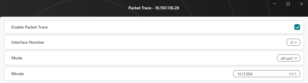
Packet Trace#
Click Packet Trace to display the following options:
Enable Packet Trace: Check this box to enable the packet trace interface on the debug adapter.
Interface Number: Select the packet trace interface number from the dropdown list on the right.
Mode: Select a mode from the dropdown list on the right.
Bitrate: Enter a bitrate value.
Terminals Menu Options
The number of options varies depending on the adapter firmware capability of the development board. The following example includes four terminals. Click the name of a terminal to view it and enter commands to communicate with it. For the Admin console, enter help to get a list of supported commands.
You are able to clear the terminal, switch between line and raw mode, and change the framer of outgoing and incoming messages.
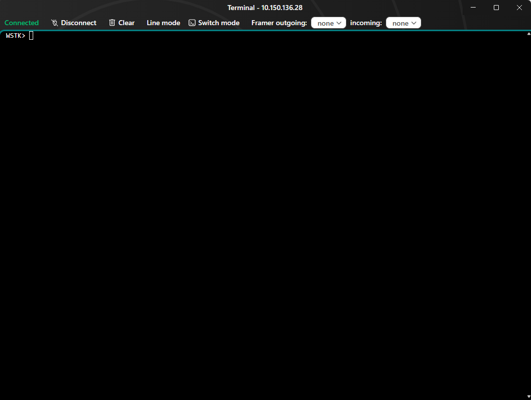
To return to the main Devices page, click < Devices at the top left corner of your screen.
Adapter Functionality When in Debug Mode OUT or MINI#
When an adapter is in debug mode OUT or MINI, Simplicity Device Manager cannot automatically determine the target part. To enable features like flashing and CTUNE configuration, you must manually add the target part using Hardware Override.
Adding the Target Part (Hardware Override)#
Open the Device Hardware page for the adapter.
Use the Hardware Override option to add the target part (click +add).
Confirm the part appears in the configured hardware view.
After adding a target part using hardware override, you will see the configured state similar to the following:
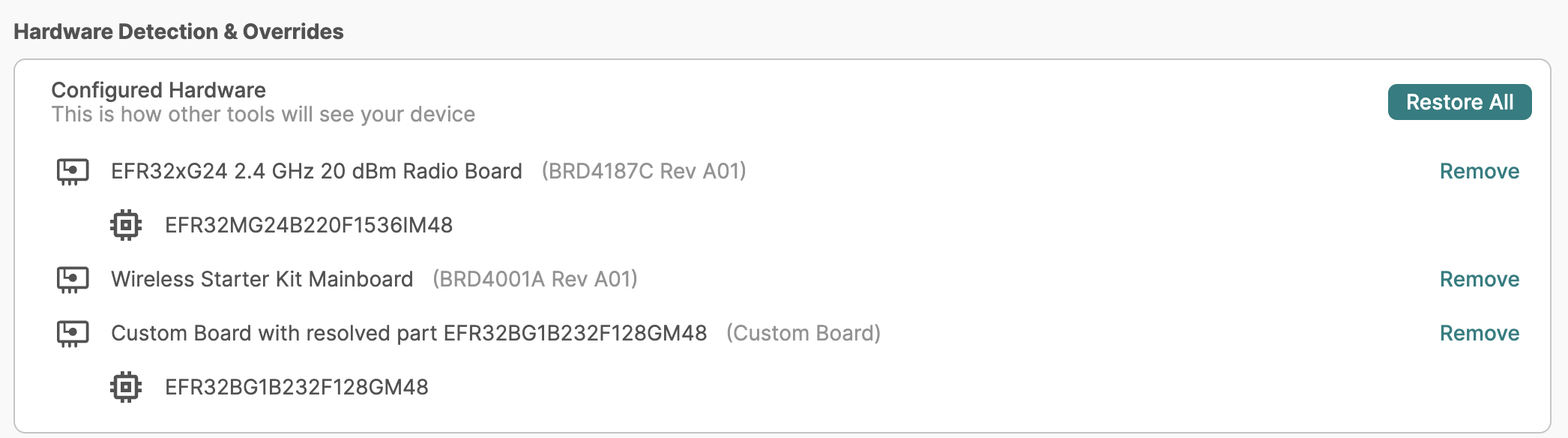
Custom Board with resolved part indicates the target part that was successfully added through hardware override.
Note: When using debug mode OUT or MINI, it is recommended to add a target part through hardware override, and to add only one part at a time.