CANopen#
CANopen is a high-level communications protocol and device-profile specification based on the CAN (Controller Area Network) protocol. It is aimed at embedded networking applications, such as in-vehicle networks. CANopen is a widespread protocol used in various industries, especially in automation and motion applications.
Micrium OS CANopen is a module designed specifically for embedded systems. Built from the ground up with Micrium’s quality, scalability, and reliability, it allows you to create networked CANopen devices with the required features.
This manual describes how to initialize, start, and use Micrium OS CANopen. It explains the various configuration values and their uses, as well as how to set up and interact with a CANopen device (also known as a node). It also provides information such as overview, configuration possibilities, implementation details and examples of typical usage.
More information on Micrium OS CANopen can be found in the following sections:
CANopen Overview#
Specifications#
The Micrium CANopen stack implementation complies with the following specification:
CiA 301: CANopen application layer and communication profile
Features#
Object Dictionary
Unlimited number of objects
Support for String objects
Support for Domain objects
Network Management (NMT) service
NMT heartbeat producer
NMT heartbeat consumer
Service Data Object (SDO) service
SDO server (up to 127 servers)
SDO expedited transfer
SDO normal transfer
Emergency (EMCY) service
EMCY producer
EMCY history
Process Data Object (PDO) service
PDO producer (up to 512 transmit PDOs)
PDO consumer (up to 512 receive PDOs)
PDO communication parameter (static and dynamic)
PDO mapping parameter (static and dynamic)
PDO synchronous cyclic/acyclic and asynchronous
Synchronization (SYNC) service
Used in conjunction with PDO synchronous cyclic/acyclic
One unique Service task within the CANopen stack, which centralizes the communication objects processing. The application does not access directly the CAN bus and can perform safe accesses to the object dictionary.
Application callbacks available to fine-tune some operations during communication objects processing by the CANopen Service task. Application callbacks are available for the following objects: NMT state transitions, PDO transfers, NMT heartbeat consumer, parameters store/restore.
Node specifications defined thanks to the CANopen Configurator tool.
Limitations#
No support for NMT error control known as node guarding (specification CiA 301). NMT node guarding is not recommended by CiA for new designs. Since the CANopen stack already supports NMT heartbeat, node guarding is not required.
No support for SDO client (specification CiA 301).
No support for SDO block transfer (specification CiA 301).
No support for EMCY consumer (specification CiA 301).
No support for PDO remote transfer (specification CiA 301).
No support for LSS used to configure the node-ID and the bit rate via the CAN network (specification CiA 305).
No support for Time Stamp object (specification CiA 301).
Integrating CANopen Into Your Project#
Micrium OS CANopen is composed of several components, each of which is a set of files that implement specific functions. To use CANopen, you must add these files to your project and populate your RTOS Description File .
Starting the CANopen Module Quickly#
Micrium offers a quick example application that demonstrates how to initialize, add a controller, and start the Micrium OS CANopen module. We highly recommend that you start with one of these examples.
The section CANopen Example Applications describes each example application.
Configuring CANopen#
Micrium OS CANopen module can be configured to optimize memory usage and features. The page CANopen Compile-Time Configuration explains how the CANopen can be configured at compile-time. The page CANopen Run-Time Configuration explains how the CANopen can be configured at run-time.
CANopen Example Applications#
This section describes the example applications for the Micrium OS CANopen stack. See Example Applications section for further information about how to enable an example application.
CANopen Module Initialization Example#
Description#
This example shows how to initialize the CANopen stack.
The CANopen module initialization example accomplishes the following tasks:
Call CANopen_Init() to initialize the CANopen resources and service task.
Call CANopen_NodeAdd() to add a node instance to the stack and configure it.
Configuration#
No specific configuration applies to this example.
Location#
/examples/canopen/ex_canopen.c
/examples/canopen/ex_canopen.h
API#
API | Description |
|---|---|
Ex_CANopen_Init() | This function performs the different example steps mentioned in the section Description . The function must be called by your application task prior to calling any other CANopen examples. |
CANopen Node Start Example#
Description#
This example shows how to start the CANopen node(s). It accomplishes the following tasks:
Call CANopen_NodeStart() to start the CAN controller associated with the node instance.
Configuration#
No specific configuration applies to this example.
Location#
/examples/canopen/ex_canopen.c
/examples/canopen/ex_canopen.h
API#
API | Description |
|---|---|
Ex_CANopen_NodeStart() | This function performs the example steps mentioned in the section Description . The function must be called by your application task prior to calling any other CANopen examples and after calling the initialization example. |
CANopen Object Dictionary Read/Write Example#
Description#
This example shows how to perform read and write operations with the CANopen Object Dictionary. It accomplishes the following tasks:
It reads the value of an object at index 0x1017 (CANopen Producer Heartbeat Time) and shows it on the console.
It writes a new value for this object entry.
It reads again the value of object 0x1017 and shows it on the console to confirm that the write operation is successful.
It sends a Node Reset message and reads again the value of object 0x1017 to show that it has come back to its default value.
It also demonstrates how the Parameter Groups and the callbacks structure work to reload parameters from a non-volatile memory. Refer to page Communication Objects Callbacks Usage for more details about the available callbacks.
Configuration#
No specific configuration applies to this example.
Location#
/examples/canopen/ex_canopen.c
/examples/canopen/ex_canopen.h
API#
API | Description |
|---|---|
Ex_CANopen_DictRdWrReset() | This function performs the example steps mentioned in the section Description . |
CANopen Configuration#
To configure Micrium OS CANopen, there are two groups of configuration parameters:
This section explains how to set up these configuration groups.
CANopen Compile-Time Configuration#
You can configure Micrium OS CANopen at compile time via a set of #defines located in canopen_cfg.h file. CANopen uses #defines when possible because they allow code and data sizes to be scaled at compile time based on enabled features. This allows the read-only memory (ROM) and random-access memory (RAM) footprints of Micrium OS CANopen to be adjusted based on application requirements.
We recommend that you begin the configuration process with the default configuration values, which are shown in bold in the next sections.
These sections are organized according to the order in Micrium OS CANopen's template configuration file, canopen_cfg.h.
Object Dictionary Configuration#
Table - Object Dictionary Configuration#
Constant | Description | Possible values |
|---|---|---|
CANOPEN_OBJ_PARAM_EN | This constant enables or disables the loading/saving of parameters from/into non-volatile memory. If enabled, the parameter callback functions are used when accessing the standard object directory entries at index 0x1010 (Store) and 0x1011 (Restore default parameters). The CANopen stack will perform some plausibility checks on the accessed entries. In case of a configuration error, the corresponding error code will be set within the node error. | DEF_ENABLED, DEF_DISABLED |
CANOPEN_OBJ_STRING_EN | This constant enables or disables the string object management inside the object dictionary. | DEF_ENABLED, DEF_DISABLED |
CANOPEN_OBJ_DOMAIN_EN | This constant enables or disables the domain object management inside the object dictionary. | DEF_ENABLED, DEF_DISABLED |
SDO Server Configuration#
Table - SDO Server Configuration#
Constant | Description | Possible values |
|---|---|---|
CANOPEN_SDO_MAX_SERVER_QTY | This constant defines the number of SDO servers for a given node. | Integer between 1 and 128 (default is 2) |
CANOPEN_SDO_DYN_ID_EN | This constant enables or disables the ability to change an SDO server COB-ID at runtime. It is possible to dynamically assign an SDO server COB-ID if certain SDO server parameters (located in the indexes range 0x1200-0x127F) have been configured to allow it. | DEF_ENABLED, DEF_DISABLED |
CANOPEN_SDO_SEG_EN | This constant enables or disables the SDO segmented transfer. The segmented transfer, also referred as a non-expedited transfer, allows you to transfer data of any size during the segment phase (upload/download SDO segment). If it is disabled, user data is limited to four bytes during the init phase of an SDO transfer (initiate SDO upload/download). | DEF_ENABLED, DEF_DISABLED |
Emergency Producer Configuration#
Table - Emergency Producer Configuration#
Constant | Description | Possible values |
|---|---|---|
CANOPEN_EMCY_MAX_ERR_QTY | This constant sets the number of emergency codes for a given node. If the emergency module is enabled, the object entries 0x1001 (Error register) and 0x1014 (COB-ID EMCY) must be configured correctly. The CANopen stack will perform some plausibility checks on the emergency entries. In case of a configuration error, the corresponding error code will be set within the node error.When this configuration is set to 0, all the Emergency service support is disabled within the stack. | Integer between 1 and 255 (default is 6) |
CANOPEN_EMCY_REG_CLASS_EN | This constant enables or disables the emergency error classes such as current, voltage, and temperature within the error register object entry (index 0x1001) considered as optional by the CiA 301 specification. | DEF_ENABLED, DEF_DISABLED |
CANOPEN_EMCY_EMCY_MAN_EN | This constant enables or disables the manufacturer-specific information field in the emergency messages. The manufacturer-specific field corresponds to 5 bytes in each 8-byte emergency message. | DEF_ENABLED, DEF_DISABLED |
CANOPEN_EMCY_HIST_EN | This constant enables or disables the emergency error history. If this configuration is set to DEF_ENABLED, the standard object directory entry 0x1003 (pre-defined error field) must be configured according to the CANopen standard. The CANopen stack will perform some plausibility checks on the emergency history entries. In case of a configuration error, the corresponding error code will be set within the node error. | DEF_ENABLED, DEF_DISABLED |
CANOPEN_EMCY_HIST_MAN_EN | This constant enables or disables the manufacturer-specific information field within the EMCY history entries, located in the standard object "pre-defined error field" at index 0x1003. If it is set to DEF_ENABLED , you can specify your own specific information by passing the correct argument to the function CANopen_EmcySet() (cf. Listing - CANopen EmcySet() Usage in the Using Communication Objects page for an example). | DEF_ENABLED, DEF_DISABLED |
Timer Configuration#
Table - Timer Configuration#
Constant | Description | Possible values |
|---|---|---|
CANOPEN_TMR_MAX_QTY | This constant sets the timer action queue length. The timer is used by some communication objects such as NMT heartbeat and by PDOs. | Integer between 1 and 255 (default is 5) |
Receive PDO Configuration#
Table - Receive PDO Configuration#
Constant | Description | Possible values |
|---|---|---|
CANOPEN_RPDO_MAX_QTY | This constant sets the number of active Receive PDOs (RPDO) for a given node. A Receive PDO is described in the node's object dictionary by the RPDO communication parameter (starting at index 0x1400) and mapping parameter (starting at index 0x 1600 ). You must correctly configure these parameters for each RPDO you use. The CANopen stack performs some plausibility checks on the communication and mapping profile of the RPDOs. In case of a configuration error, the corresponding error code will be set within the node error.When this configuration is set to 0, all the RPDO service support is disabled within the stack. | Integer between 1 and 512 (default is 4) |
CANOPEN_RPDO_MAX_MAP_QTY | This constant sets the number of receive PDO mapping objects. | Integer between 1 and 64 (default is 2) |
CANOPEN_RPDO_DYN_COM_EN | This constant enables or disables support for dynamic communication profiles within the standard RPDO object entries at index 0x1400 (RPDO communication parameter). | DEF_ENABLED, DEF_DISABLED |
CANOPEN_RPDO_DYN_MAP_EN | This constant enables or disables support for dynamic mapping profiles within the standard RPDO object entries at index 0x1600 (RPDO mapping parameter). Setting this configuration to DEF_ENABLED requires you to also enable support for dynamic communication profiles, constant CANOPEN_RPDO_DYN_COM_EN. | DEF_ENABLED, DEF_DISABLED |
Transmit PDO Configuration#
Table - Transmit PDO Configuration#
Constant | Description | Possible values |
|---|---|---|
CANOPEN_TPDO_MAX_QTY | This constant sets the number of active Transmit PDOs (TPDO) for a given node. A Transmit PDO is described in the node's object dictionary by the TPDO communication parameter (starting at index 0x1800) and mapping parameter (starting at index 0x1A00). You must correctly configure these parameters for each TPDO you use. The CANopen stack performs some plausibility checks on the communication and mapping profile of the TPDOs. In case of a configuration error, the corresponding error code will be set within the node error.When this configuration is set to 0, all the TPDO service support is disabled within the stack. | Integer between 1 and 512 (default is 4) |
CANOPEN_TPDO_MAX_MAP_QTY | This constant sets the number of transmit PDO mapping objects. | Integer between 1 and 64 (default is 2) |
CANOPEN_TPDO_DYN_COM_EN | This constant enables or disables the support of dynamic communication profile within the standard TPDO object entries at index 0x1800 (TPDO communication parameter). | DEF_ENABLED, DEF_DISABLED |
CANOPEN_TPDO_DYN_MAP_EN | This constant enables or disables the support of dynamic mapping profile within the standard TPDO object entries at index 0x1A00 (TPDO mapping parameter). | DEF_ENABLED, DEF_DISABLED |
SYNC Consumer Configuration#
Table - SYNC Consumer Configuration#
Constant | Description | Possible values |
|---|---|---|
CANOPEN_SYNC_EN | This constant enables or disables the use of synchronous PDOs. | DEF_ENABLED, DEF_DISABLED |
Debug Configuration#
Table - Debug Configuration#
Constant | Description | Possible values |
|---|---|---|
CANOPEN_DBG_CTR_ERR_EN | This constant enables or disables the error counters inside the stack. When enabled, if errors occur during the CAN frames decoding and processing by the CANopen Service task, these errors will be recorded into internal counters. The error counters are per node instance. | DEF_ENABLED, DEF_DISABLED |
CANopen Run-Time Configuration#
This section describes the application-specific configurations of the Micrium OS CANopen module, that are specified at run-time. For more information on how to initialize any Micrium OS module, see Stacks Initialization Methods .
Core Configuration#
To initialize the Micrium OS CANopen module, you must call the function CANopen_Init(). This function does not have any configuration argument.
Optional Pre-Init Configuration#
To perform pre-init configuration, you must call the dedicated configuration functions before calling CANopen_Init(). If no explicit pre-init configuration is performed, default values will be used. These default values are stored in CANopen_InitCfgDflt defined in canopen_core.c.
Memory Segment#
Configures the memory segment where the core internal data structures will be allocated.
Type | Function to call | Default | Field from default configuration structure |
|---|---|---|---|
MEM_SEG* | CANopen_ConfigureMemSeg() | .MemSegPtr |
Maximum Number of Service Task Events#
Configures the maximum number of service task events.
Type | Function to call | Default | Field from default configuration structure |
|---|---|---|---|
CPU_SIZE_T | CANopen_ConfigureEventQty() | 25 | .EventQtyTot |
Service Task Stack#
Configures the size and the start address of the Service task stack.
Type | Function to call | Default | Field from default configuration structure |
|---|---|---|---|
CPU_INT32U | CANopen_ConfigureSvcTaskStk() | A stack of 512 elements. | .SvcTaskStkSizeElements |
void * | CANopen_ConfigureSvcTaskStk() | A stack allocated on Common 's memory segment, | .SvcTaskStkPtr |
Hardware Timer Period#
Configures the hardware timer period in microseconds. A hardware timer is used by some communication object services such as the NMT heartbeat error control and PDOs.
Type | Function to call | Default | Field from default configuration structure |
|---|---|---|---|
CPU_INT32U | CANopen_ConfigureTmrPeriod() | 1000 microseconds | .HwTmrPeriod |
Optional Post-Init Configuration#
This section describes configurations that can be set at any time during execution after CANopen_Init() has been called. These configurations are optional. If you do not set them in your application, the default configurations will apply.
Service Task Priority#
Sets the priority of the Service task.
Type | Function to call | Default |
|---|---|---|
RTOS_TASK_PRIO | CANopen_SvcTaskPrioSet() |
Node Lock Timeout#
Sets the Node Lock timeout expressed in milliseconds. The node lock is used to protect access to the object dictionary.
Type | Function to call | Default |
|---|---|---|
CPU_INT32U | CANopen_NodeLockTimeoutSet() | Infinite timeout |
CANopen Programming Guide#
This section explains how to use the CANopen module.
Initial Setup of CANopen Module#
This section describes the basic steps required to initialize the CANopen module, and to add, start and stop a CANopen node.
Initializing the CANopen Module#
The first step is to initialize the CANopen module core. This is done by calling the function CANopen_Init() . When called, this function will allocate any internal resources needed by the stack and will create the service stack responsible for the CANopen communication objects.
Listing - Example of Call to CANopen Init() in the Initial Setup of CANopen Module page shows an example of a call to the function CANopen_Init().
Listing - Example of Call to CANopen_Init()#
RTOS_ERR err;
CANopen_Init(&err);
if (err.Code != RTOS_ERR_NONE) {
/* An error occurred. Error handling should be added here. */
}Adding Your CANopen Node(s)#
The CANopen stack supports multiple nodes. A node refers to a CANopen device. The function CANopen_NodeAdd() allows you to add a node to the CANopen stack and to configure it. The function CANopen_NodeAdd() can be called for each node you need to support. A node is associated with one unique CAN bus controller.
Listing - Example of Call to CANopen NodeAdd() in the Initial Setup of CANopen Module page shows an example that adds a node. More information about the node specifications configuration can be found in Defining Node Specifications . You can look at Communication Objects Callbacks Usage for more details about the different object callbacks available to your application. If you need to override the default CANopen stack configuration, you can call the CANopen_ConfigureXxxx() functions (cf. CANopen Run-Time Configuration for more details) before calling CANopen_NodeAdd().
Listing - Example of Call to CANopen_NodeAdd()#
const CANOPEN_NODE_SPEC Ex_CANopen_NodeSpec = { /* CONFIGURATION FOR NODE 1. */
.NodeId = 0x1, /* Pre-defined Node-ID. */
.Baudrate = 125000, /* Default baudrate. */
.DictPtr = (CANOPEN_OBJ *)&Ex_ObjDict1, /* Start of object directory. */
.DictLen = sizeof(Ex_ObjDict1)/sizeof(CANOPEN_OBJ), /* Number of objects in directory. */
.EmcyCodePtr = (CANOPEN_EMCY_TBL *)&Ex_EmcyTbl, /* Start of emergency code table. */
.TmrMemPtr = (CANOPEN_TMR_MEM *)&Ex_TmrMem1, /* Start of timer manager memory. */
.TmrQty = sizeof(Ex_TmrMem1)/sizeof(CANOPEN_TMR_MEM), /* Maximum number of timers/actions. */
.SdoBufPtr = (CPU_INT08U *)&Ex_SdoBuf1 /* Start of SDO transfer buffer. */
};
const CANOPEN_EVENT_FNCTS Ex_EventsCB = { /* EVENTS CALLBACKS FOR NODE 1. */
.RpdoOnRx = DEF_NULL,
.TpdoOnTx = DEF_NULL,
.StateOnChange = DEF_NULL,
.HbcOnEvent = DEF_NULL,
.HbcOnChange = DEF_NULL,
.ParamOnLoad = Ex_Param_OnLoad,
.ParamOnSave = DEF_NULL,
.ParamOnDflt = DEF_NULL
};
CANOPEN_NODE_HANDLE Ex_CANopen_Node1Handle;
void Ex_CANopen_Init (void)
{
RTOS_ERR err;
/* The CANopen stack has been previously initialized with CANopen_Init(). */
/* Add node 1 to the CANopen stack with the default stack configuration. */
Ex_CANopen_Node1Handle = CANopen_NodeAdd("can0", /* Node 1 associated w/ controller "can0". */
&Ex_CANopen_NodeSpec, /* Reference to node specifications. */
&Ex_EventsCB, /* Reference to node event callbacks. */
&err);
if (err.Code != RTOS_ERR_NONE) {
/* An error occurred. Error handling should be added here. */
}
}Starting Your CANopen Node(s)#
Once you have successfully added your node(s), you must start it/them. This is done by calling the function CANopen_NodeStart() . This function must be called for each node you have added. The function will start the operations of the CAN bus controller associated with this node. If the node is already in the "initializing" state according to the CANopen NMT (Network Management), the bootup message will be sent to the NMT master node. Later, you may want to stop your node(s) by calling CANopen_NodeStop() . Once the node is started, it advertises its presence on the bus and is put in the pre-operational state. At that point, a master device can issue an NMT message to put it in the Operational state.
Listing - Example of Call to CANopen NodeStart() in the Initial Setup of CANopen Module page shows an example of a call to CANopen_NodeStart().
Listing - Example of Call to CANopen_NodeStart()#
RTOS_ERR err;
CANOPEN_NODE_HANDLE node1_handle;
/* The CANopen stack has been previously initialized with CANopen_Init(). */
/* The node has been added to the stack with CANopen_NodeAdd(), which */
/* returned the handle to use for further operations on the node. */
/* Start node 1 operations. */
CANopen_NodeStart(&node1_handle,
&err);
if (err.Code != RTOS_ERR_NONE) {
/* An error occurred. Error handling should be added here. */
}Defining Node Specifications#
This section describes how to define a specifications structure for a given node.
The node specifications structure is used to configure a node with parameters such as the node ID, the speed of communication between the nodes, and others. To save time, you can use CANopen Configurator to generate the configuration structure for each node on the network.
Node Specification#
When you add a node (by using CANopen NodeAdd() ), you must provide the node's specifications. The node specification contains information that ties the CAN bus and your application together to the CANopen stack. This structure can be generated automatically using CANopen Configurator. This tool simplifies the generation of the object dictionary associated with the node, and it also produces an EDS file for your node. Some fields of the node specifications structure can be entered directly in the tool and some are derived from other configuration values. Table - Node Specification Description in the Defining Node Specifications page shows each element of the node specification structure.
Listing - Node Specification Structure#
typedef struct canopen_node_spec {
CPU_INT08U NodeId;
CPU_INT32U Baudrate;
CANOPEN_OBJ *DictPtr;
CANOPEN_EMCY_TBL *EmcyCodePtr;
CANOPEN_TMR_MEM *TmrMemPtr;
CPU_INT16U TmrQty;
CPU_INT08U *SdoBufPtr;
} CANOPEN_NODE_SPEC;Table - Node Specification Description#
Type | Name | Description | Configuration when using CANopen Configurator tool |
|---|---|---|---|
CPU_INT08U | NodeId | Default Node ID | User-defined directly within the configuration tool |
CPU_INT32U | Baudrate | Default baud rate | User-defined directly within the configuration tool |
CANOPEN_OBJ * | DictPtr | Node object dictionary pointer | Name of the array is predefined and derived from NodeId Size of the array is based on how many entries you have defined in the Object Dictionary tab of the configuration tool. |
CANOPEN_EMCY_TBL * | EmcyCodePtr | Application emergency information pointer | Name of the array is predefined and derived from NodeId Size of the array is based on a user-defined value of CANOPEN_EMCY_MAX_ERR_QTY set within the configuration tool. |
CANOPEN_TMR_MEM * | TmrMemPtr | Timer memory block | Name of the array is predefined and derived from NodeId Size of the array is based on a user-defined value of CANOPEN TMR MAX QTY set within the configuration tool. |
CPU_INT16U | TmrQty | Number of timer memory blocks | Number of TmrMemPtr array elements |
CPU_INT08U * | SdoBufPtr | SDO Transfer Buffer Memory Start | Name of the array is predefined and derived from NodeId Size of array is based on a user-defined value of CANOPEN SDO MAX SERVER QTY set within the configuration tool. |
Listing - Node Specification Example#
const CANOPEN_OBJ Ex_ObjDict1[] = {
{ CANOPEN_KEY(0x1000,0x0, CANOPEN_OBJ_UNSIGNED32|CANOPEN_OBJ____R_), 0, (CPU_INT32U)&Ex_Var_1000_0 },
{ CANOPEN_KEY(0x1001,0x0, CANOPEN_OBJ_UNSIGNED8 |CANOPEN_OBJ____R_), 0, (CPU_INT32U)&Ex_Var_1001_0 },
CANOPEN_OBJ_DICT_ENDMARK
};
CANOPEN_TMR_MEM Ex_TmrMem1[CANOPEN_TMR_MAX_QTY]; /* Allocation of Timer memory blocks. */
CANOPEN_EMCY_TBL Ex_EmcyTbl[CANOPEN_EMCY_MAX_ERR_QTY] = {
{ 0, 0x1000 },
{ 1, 0x1001 },
};
CPU_INT08U Ex_SdoBuf1[CANOPEN_SDO_MAX_SERVER_QTY]; /* Allocation of SDO transfer memory. */
const CANOPEN_NODE_SPEC Ex_CANopen_NodeSpec = {
.NodeId = 0x1,
.Baudrate = 125000,
.DictPtr = (CANOPEN_OBJ *)&Ex_ObjDict1,
.EmcyCodePtr = (CANOPEN_EMCY_TBL *)&Ex_EmcyTbl,
.TmrMemPtr = (CANOPEN_TMR_MEM *)&Ex_TmrMem1,
.TmrQty = sizeof(Ex_TmrMem1)/sizeof(CANOPEN_TMR_MEM),
.SdoBufPtr = (CPU_INT08U *)&Ex_SdoBuf1
};Structure Details#
.NodeId#
The Node ID uniquely identifies one CAN device on a network. Because a device could have more than one CAN bus, the Node ID is also used when naming variables to prevent name clashes. For instance, if your device uses nodes 1 and 3, their object dictionary, as generated by the configuration tool, will be named Ex_ObjDict1 and Ex_ObjDict3.
.Baudrate#
The baud rate is used to configure the CAN bus to operate at the specified speed, expressed in kbit/s. Its value must be among the ones set by the CANopen standard: 10k, 20k, 50k, 125k, 250k, 500k, 800k, 1000k.
.DictPtr#
DictPtr is a pointer to an array of CANOPEN OBJ , representing the node's Object Dictionary. We recommend that you use the configuration tool to generate the object dictionary, as its content may be too complex to handle manually.
.EmcyCodePtr#
EmcyCodePtr is a pointer to an array containing a map of user emergency codes. The array is of type CANOPEN_EMCY_TBL . Each element in this array has two parts: an emergency code and a number that maps the error code to a bit in the Error Register (index 0x1001).
For instance, in the Ex_EmcyTbl[] variable above, error 0x1000 maps to bit 0 of the error register.
During the node setup, an emergency structure is assigned to the node. The aforementioned user emergency table is placed in this structure, as well as counters to keep track of each type of error code received.
.TmrMemPtr / .TmrQty#
This is a pointer to an array of one or more timer memory structures. A timer memory structure is made up of two elements:
The Timer structure, which manages the timer queue
The Action structure, which manages the action queue for a timer, including settings such as callback function and parameters, and cycle time in the case of periodic actions
.SdoBufPtr#
The SDO Buffer is used to temporarily hold data in an SDO transfer. Because an SDO transfer can be broken into multiple messages, a buffer is required to reassemble the transfer into a consistent state.
CANopen Configurator Tool#
This application is provided to help you create and maintain an object dictionary and generate relevant C code, including the structures and configuration files needed by the CANopen module.
This section explains the relationship between the above structural elements and the configuration tool.
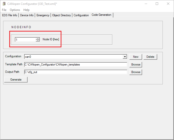
Node ID#
The default node ID (.NodeId) can be changed by editing the "Node ID" field in the Code Generation tab. Figure - Default Node-ID in the Defining Node Specifications page shows where to change it.
Figure - Default Node-ID#
Baud Rate#
The default CAN Bus baud rate (.Baudrate) can be changed by selecting a new baud rate in the Device Info tab. Figure - Default Baudrate in the Defining Node Specifications page shows where to change it.
Figure - Default Baudrate#

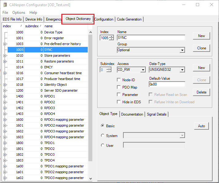
Object Dictionary#
.DictPtr is related to the Object Dictionary. The object dictionary is set up through its own tab named Object Dictionary. Figure - Object Dictionary in the Defining Node Specifications page shows where to change it.
The number of entries in the dictionary (plus 1 for an end marker) establishes the size of the array pointed to by DictPtr.
Figure - Object Dictionary#
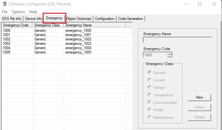
Emergency Codes#
.EmcyCodePtr is related to the Emergency objects. The Emergency objects are configured through the Emergency tab. Figure - Emergency Objects in the Defining Node Specifications page shows where to change it.
Figure - Emergency Objects#
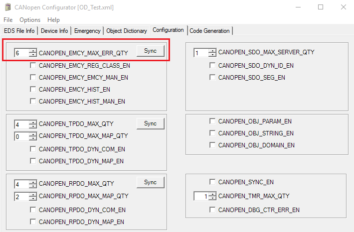
The size of the .EmcyCodePtr array (Ex_EmcyTbl[] in the example above) is determined by the value of CANOPEN_EMCY_MAX_ERR_QTY, which can be set in the Configuration tab of the tool. The value can be entered manually, or the Sync button may be used to retrieve the number of entries defined in the Emergency tab. Figure - Emergency Configuration in the Defining Node Specifications page shows where to change it.
Figure - Emergency Configuration#
Timers#
.TmrMemPtr and .TmrQty are related to CANopen Timers management. The only relevant user-defined value is the number of timers, which can be set in the Configuration tab. Figure - Timers in the Defining Node Specifications page shows where to change it. The number of timers (CANOPEN_TMR_MAX_QTY) is used to determine the size of the Timers memory block array (Ex_TmrMem1[] in the example above).
Figure - Timers#
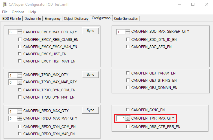
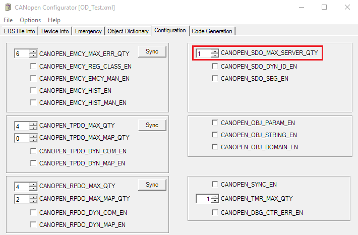
SDO Buffer#
.SdoBufPtr is related to the handling of SDO segments. The only relevant user-defined value is the number of SDO servers (CANOPEN_SDO_MAX_SERVER_QTY), which can be set in the Configuration tab. Figure - SDO Buffer in the Defining Node Specifications page shows where to change it. This value is used to determine the size of the SDO Transfer Memory array (Ex_SdoBuf1[] in the example above).
Figure - SDO Buffer#
Communication Objects Callbacks Usage#
This section explains the callback functions that are available for use by some communication objects. These callbacks allow your application to customize certain actions while the CANOpen stack is processing communication objects.
The callbacks are available for the following CANopen services processing:
Parameters
Process Data Object (PDO)
Network Management (NMT)
Heartbeat consumer (NMT error control)
Initializing Callbacks#
Communication object callbacks can be set when calling CANopen_NodeAdd(). The second parameter of this function takes a pointer to a CANOPEN_EVENT_FNCTS structure. Listing - Communication Object Callbacks in the Communication Objects Callbacks Usage page provides an example of how to declare the callbacks.
Listing - Communication Object Callbacks#
RTOS_ERR err;
CANOPEN_NODE_HANDLE node_handle;
CANOPEN_NODE_SPEC spec_node;
CANOPEN_EVENT_FNCTS event_fnt = {
.RpdoOnRx = &RpdoOnRx,
.TpdoOnTx = &TpdoOnTx,
.StateOnChange = &StateOnChange,
.HbcOnEvent = &HBCOnEvent,
.HbcOnChange = &HbcOnChange,
.ParamOnLoad = &ParamOnLoad,
.ParamOnSave = &ParamOnSave,
.ParamOnDflt = &ParamOnDflt
};
node_handle = CANopen_NodeAdd(&spec_node,
&event_fnt,
&err);
APP_RTOS_ASSERT_DBG((err.Code == RTOS_ERR_NONE), ;);Parameters#
Your application has access to three callbacks to manage the storing and restoring of object dictionary parameters. Listing - Example of CANOPEN PARAM Usage in the Communication Objects Callbacks Usage page provides a basic definition of an object dictionary with the store and restore features enabled and shows an example of how to declare the parameters group.
Listing - Example of CANOPEN_PARAM Usage#
typedef struct APP_PARAM_GROUP {
CPU_INT32U AppVar_1005_0; /* ------------------ [1005:0] SYNC ------------------- */
CPU_INT32U AppVar_1010_0; /* [1010:0] Store parameters */
CPU_INT32U AppVar_1010_1; /* [1010:1] Save all parameter */
CPU_INT08U AppVar_1011_0; /* [1011:0] Restore parameters */
CPU_INT32U AppVar_1011_1; /* [1011:1] Restore all parameter */
} APP_PG;
...
APP_PG App_ParamGrp = { (1)
.AppVar_1005_0 = 0x80,
.AppVar_1010_0 = 1,
.AppVar_1010_1 = 1,
.AppVar_1011_0 = 1,
.AppVar_1011_1 = 1,
};
APP_PG App_ParamDef = { (2)
.AppVar_1005_0 = 0x80,
.AppVar_1010_0 = 0,
.AppVar_1010_1 = 0,
.AppVar_1011_0 = 0,
.AppVar_1011_1 = 0,
};
...
const CANOPEN_PARAM App_ParamGrpCfg = { (3)
.MemBlkSize = sizeof(APP_PG),
.StartMemBlkPtr = (CPU_INT08U *)&App_ParamGrp,
.DfltMemBlkPtr = (CPU_INT08U *)&App_ParamDef,
.ResetType = CANOPEN_RESET_COMM, (4)
.IdPtr = (void*)"AppParam",
.Val = CANOPEN_PARAM___E
};
...
const CANOPEN_OBJ AppObjDir[] = {
/*--------------------------------------------------------------------------------------------*/
/* [1005:xx] - SYNC */
{ CANOPEN_KEY(0x1005,0x0, CANOPEN_OBJ_UNSIGNED32|CANOPEN_OBJ____RW), 0,
(CPU_INT32U)&App_ParamGrp.AppVar_1005_0 },
/*--------------------------------------------------------------------------------------------*/
/* [1010:xx] - Store parameters */
{ CANOPEN_KEY(0x1010,0x0, CANOPEN_OBJ_UNSIGNED8|CANOPEN_OBJ____R_), 0,
(CPU_INT32U)&App_ParamGrp.AppVar_1010_0 },
{ CANOPEN_KEY(0x1010,0x1, CANOPEN_OBJ_UNSIGNED32|CANOPEN_OBJ____RW), CANOPEN_OBJ_TYPE_PARAM,
(CPU_INT32U)&App_ParamGrpCfg }, (5)
/*--------------------------------------------------------------------------------------------*/
/* [1011:xx] - Restore parameters */
{ CANOPEN_KEY(0x1011,0x0, CANOPEN_OBJ_UNSIGNED8|CANOPEN_OBJ____R_), 0,
(CPU_INT32U)&App_ParamGrp.AppVar_1011_0 },
{ CANOPEN_KEY(0x1011,0x1, CANOPEN_OBJ_UNSIGNED32|CANOPEN_OBJ____RW), CANOPEN_OBJ_TYPE_PARAM,
(CPU_INT32U)&App_ParamGrpCfg },
CANOPEN_OBJ_DICT_ENDMARK
};(1) This structure holds all the values used by the object dictionary. All these values can be restored to their original state using the communication object at index 0x1011 (restore parameters).
(2) This structure holds the default values of a specific part of the object dictionary. These values are written back to the object dictionary when using the communication object at index 0x1011 (restore parameters).
(3) This structure is used to store pointers to data structures such as the default and current values of the object dictionary.
(4) Specifies the reset type for a parameter group. This can be CANOPEN_RESET_NODE or CANOPEN_RESET_COMM. If CANOPEN_RESET_NODE is used, the parameters of the manufacturer-specific profile area and the standardized device profile area are both set to their power-on values. If CANOPEN_RESET_COMM is used, the parameters of the communication profile area are set to their power-on values.
(5) A pointer to the configuration structure must be passed as data to the store/restore communication object into the object dictionary.
ParamOnLoad()#
This callback is of type ParamOnLoad(). This callback is optional and must be defined in your application.
The callback restores the current object dictionary with default values from a memory segment. Listing - ParamOnLoad() Example in the Communication Objects Callbacks Usage page show a basic implementation of the ParamOnLoad() callback.
Listing - ParamOnLoad() Example#
CPU_BOOLEAN Ex_ParamOnLoad (CANOPEN_NODE_HANDLE handle,
CANOPEN_PARAM *p_pg)
{
PP_UNUSED_PARAM(handle);
Mem_Copy(p_pg->StartMemBlkPtr, /* Pointer to parameter memory block in object dictionary. */
p_pg->DfltMemBlkPtr, /* Pointer to memory segment from where values are restored. */
p_pg->MemBlkSize);
return (DEF_TRUE);
}ParamOnSave()#
This callback is of type ParamOnSave(). This callback is optional and must be defined in your application.
The callback is called when a master writes a valid signature at the index 0x1010 (store parameters) of the node's object dictionary. The signature that enables the parameters to be stored is "save" – that is, in hexadecimal, 0x65766173, which represents 'e', 'v', 'a', 's'.
The current state of the object dictionary is saved into memory for future use.
Listing - ParamOnSave() Example#
CPU_BOOLEAN Ex_ParamOnSave (CANOPEN_NODE_HANDLE handle,
CANOPEN_PARAM *p_pg)
{
/* The object dictionary must be stored somewhere in memory for future use.
The pointer p_pg->StartMemBlkPtr contains the address of the first entry
of the object dictionary. The number of bytes in the object dictionary
is given by p_pg->MemBlkSize. */
return (DEF_TRUE);
}ParamOnDflt()#
This callback is of type ParamOnDflt(). This callback is optional and must be defined in your application.
The callback is called when a master writes a valid signature at the index 0x1011 (restore default parameters) of the node's object dictionary. The signature that enables the default parameters to be restored is "load" – that is, in hexadecimal, 0x64616F6C, which represents 'd', 'a', 'o', 'l'. Listing - ParamOnDflt() Example in the Communication Objects Callbacks Usage page shows a basic implementation of the ParamOnDflt() callback.
Listing - ParamOnDflt() Example#
CPU_BOOLEAN Ex_ParamOnDflt (CANOPEN_NODE_HANDLE handle,
CANOPEN_PARAM *p_pg)
{
PP_UNUSED_PARAM(handle);
Mem_Copy(p_pg->StartMemBlkPtr, /* Pointer to parameter memory block in object dictionary. */
p_pg->DfltMemBlkPtr, /* Pointer to memory segment from where values are restored. */
p_pg->MemBlkSize);
return (DEF_TRUE);
}PDO#
PDO callbacks are useful for checking data payloads after a PDO message is received or before it is transmitted. This payload data is stored in the second argument of each PDO callback.
This structure is used to store various information about a message received from or transmitted to the bus. CANOPEN_IF_FRM shows a brief description of each argument of the following structure.
Listing - CANopen Frame Structure#
typedef struct canopen_if_frm {
CPU_INT32U MsgId;
CPU_INT08U Data[8];
CPU_INT08U DLC;
CPU_INT08U MsgNum;
} CANOPEN_IF_FRM;TpdoOnTx()#
TpdoOnTx() is called before every TPDO transmission. It can be used to change the PDO data before sending it.
This callback is of type TpdoOnTx(). TpdoOnTx() is optional and must be defined in your application. Listing - TpdoOnTx() Example in the Communication Objects Callbacks Usage page shows a basic implementation of the TpdoOnTx() callback.
Listing - TpdoOnTx() Example#
void Ex_TpdoOnTx (CANOPEN_NODE_HANDLE handle,
CANOPEN_IF_FRM *p_frm)
{
PP_UNUSED_PARAM(handle);
/* Change payload data before sending it over the bus. */
p_frm->Data[0u] = 1u;
p_frm->Data[1u] = 2u;
p_frm->Data[2u] = 3u;
p_frm->Data[3u] = 4u;
p_frm->DLC = 4u; /* Change the message length. */
}RpdoOnRx()#
RpdoOnRx() is called every time an asynchronous RPDO message is received.
This callback is of type RpdoOnRx(). RpdoOnRx() is optional and must be defined in your application. Listing - RpdoOnRx() Example in the Communication Objects Callbacks Usage page shows a basic implementation of the RpdoOnRx() callback.
Listing - RpdoOnRx() Example#
void Ex_RpdoOnRx (CANOPEN_NODE_HANDLE handle,
CANOPEN_IF_FRM *p_frm)
{
PP_UNUSED_PARAM(handle);
for (CPU_INT32U loop = 0; loop < p_frm->DLC; loop ++) {
printf("%d ", p_frm->Data[loop]); /* Print every characters from the data payload. */
}
}NMT#
The node's NMT feature (Network Management) allows a master to control the internal node states by sending commands over the CAN bus. One unique callback allows the user application to be notified about a state transition.
Listing - CANopen State Enumeration in the Communication Objects Callbacks Usage page is used to define the different states taken by a node. CANOPEN_NODE_STATE shows a brief description of each enumeration state.
Listing - CANopen State Enumeration#
typedef enum canopen_node_state {
CANOPEN_INVALID = 0,
CANOPEN_INIT,
CANOPEN_PREOP,
CANOPEN_OPERATIONAL,
CANOPEN_STOP,
CANOPEN_STATE_QTY
} CANOPEN_NODE_STATE;StateOnChange()#
This callback is used when the NMT state is changed. This callback is of type StateOnChange(). This callback is optional and must be defined in your application.
Heartbeat Consumer#
Two callbacks are available to notify your application about the heartbeat producer activity.
HbcOnEvent()#
This callback is used when a heartbeat consumer timer elapses and is triggered before receiving the corresponding heartbeat message from the heartbeat producer being monitored.
This callback is of type HbcOnEvent() . This callback is optional and must be defined in your application.
HbcOnChange()#
This callback is used when a heartbeat consumer monitor detects a state change in a monitored node.
This callback is of type HbcOnChange(). This callback is optional and must be defined in your application.
HbcOnChange Callback#
This callback function is called during the CANopen activities for a heartbeat consumer detected NMT mode change. The function is intended to allow the application to perform specific functions on NMT state change in received heartbeats.
Prototype#
void (*HbcOnChange) (CANOPEN_NODE_HANDLE handle, CPU_INT08U node_id, CANOPEN_NODE_STATE state);
Arguments#
handle
Handle to CANopen node object.
node_id
Node ID of the consumed heartbeat message.
state
Node state.
Return Values#
None.
Notes / Warnings#
None.
HbcOnEvent Callback#
This callback function is called during the CANopen activities when a heartbeat consumer detects missed deadline of the monitored node. The function is intended to allow the application to perform specific actions on missing heartbeat events.
Prototype#
void (*HbcOnEvent) (CANOPEN_NODE_HANDLE handle, CPU_INT08U node_id);
Arguments#
handle
Handle to CANopen node object.
node_id
Node ID of the consumed heartbeat message.
Return Values#
None.
Notes / Warnings#
None.
ParamOnDflt Callback#
This callback is used when the standard object "Restore default parameters" at index 0x1011 is written. The function is intended to restore the default parameters values from the non-volatile memory to the object dictionary.
Prototype#
CPU_BOOLEAN (*ParamOnDflt) (CANOPEN_NODE_HANDLE handle, CANOPEN_PARAM *p_pg);
Arguments#
handle
Handle to CANopen node object.
p_pg
Pointer to a parameter group information.
Return Values#
DEF_YES, if load was successful.
DEF_NO, if load encountered an error.
Notes / Warnings#
None.
ParamOnLoad Callback#
The callback is called during reset and power-up events, including the NMT reset node and reset communication request. The function is intended to access the non-volatile memory and setting the parameter variables to the stored values.
Prototype#
CPU_BOOLEAN (*ParamOnLoad) (CANOPEN_NODE_HANDLE handle, CANOPEN_PARAM *p_pg);
Arguments#
handle
Handle to CANopen node object.
p_pg
Pointer to a parameter group information.
Return Values#
DEF_YES, if load was successful.
DEF_NO, if load encountered an error.
Notes / Warnings#
None.
ParamOnSave Callback#
This callback is used when the standard object "Store" at index 0x1010 is written. The function is intended to save the parameters values to the non-volatile memory.
Prototype#
CPU_BOOLEAN (*ParamOnSave) (CANOPEN_NODE_HANDLE handle, CANOPEN_PARAM *p_pg);
Arguments#
handle
Handle to CANopen node object.
p_pg
Pointer to a parameter group information.
Return Values#
DEF_YES, if load was successful.
DEF_NO, if load encountered an error.
Notes / Warnings#
None.
RpdoOnRx Callback#
This callback function is called after the reception of a RPDO CAN frame. The function is intended to allow a filter mechanism or modifications on the RPDO before distribution of the CAN frame into the CANopen stack.
Prototype#
CPU_INT16S (*RpdoOnRx) (CANOPEN_NODE_HANDLE handle, CANOPEN_IF_FRM *p_frm);
Arguments#
handle
Handle to CANopen node object.
p_frm
Pointer to the received frame buffer.
Return Values#
1, if message was consumed by the callback.
0, if message was not consumed by the callback.
Notes / Warnings#
None.
StateOnChange Callback#
This callback function is called during the CANopen activities for a specific NMT state change. The function is intended to allow the application to perform specific actions on NMT state change events from the CANopen network (e.g., Reset, Stop, etc.).
Prototype#
void (*StateOnChange) (CANOPEN_NODE_HANDLE handle, CANOPEN_NODE_STATE state);
Arguments#
handle
Handle to CANopen node object.
state
Node state.
Return Values#
None.
Notes / Warnings#
None.
TpdoOnTx Callback#
This callback function is called just before transmission of the built transmit PDO CAN frame. The function is intended to allow a 'last minute' customer specific modification on the TPDO data payload.
Prototype#
void (*TpdoOnTx) (CANOPEN_NODE_HANDLE handle, CANOPEN_IF_FRM *p_frm);
Arguments#
handle
Handle to CANopen node object.
p_frm
Pointer to the transmitted frame buffer.
Return Values#
None.
Notes / Warnings#
None.
Accessing Object Dictionary#
This section shows how the object dictionary works, how it is structured, and how to access it from your application.
Object Dictionary#
CANopen Object#
The object dictionary is used to configure and communicate with a given CANopen node. An object dictionary is linked with an EDS (electronic data sheet) file, which is read by the CANopen master to discover the object dictionary entries for a given node.
The object dictionary consists of an array of CANOPEN_OBJ . Each entry of this array has:
A key to encode index, sub-index, and information about the data
An optional type that contains a callback structure related to the data
A data payload that contains the direct object value, or an address to a memory region that holds the object's value, which can be simple or complex
Listing - Object Dictionary Example in the Accessing Object Dictionary page shows a basic example of an object dictionary.
Defining an object dictionary, as presented in Listing - Object Dictionary Example in the Accessing Object Dictionary page, can be challenging. A tool called "CANopen Configurator" can be used to generate the node configuration structure and its associated object dictionary. Refer to Defining Node Specifications for more details about the tool "CANopen Configurator". |
|---|
Listing - Object Dictionary Example#
const CANOPEN_OBJ AppObjDir[] = {
/*--------------------------------------------------------------------------------------------*/ |
/* [1000:xx] - Device Type */
{ CANOPEN_KEY(0x1000,0x0, CANOPEN_OBJ_UNSIGNED32|CANOPEN_OBJ____R_), 0,
(CPU_INT32U)&App_ParamGrp.AppVar_1000_0 },
/*--------------------------------------------------------------------------------------------*/
/* [1001:xx] - Error register */
{ CANOPEN_KEY(0x1001,0x0, CANOPEN_OBJ_UNSIGNED8|CANOPEN_OBJ____R_), 0,
(CPU_INT32U)&App_ParamGrp.AppVar_1001_0 },
/*--------------------------------------------------------------------------------------------*/
/* [1005:xx] - SYNC */
{ CANOPEN_KEY(0x1005,0x0, CANOPEN_OBJ_UNSIGNED32|CANOPEN_OBJ____RW), 0,
(CPU_INT32U)&App_ParamGrp.AppVar_1005_0 },
/*--------------------------------------------------------------------------------------------*/
/* [1010:xx] - Store parameters */
{ CANOPEN_KEY(0x1010,0x0, CANOPEN_OBJ_UNSIGNED8|CANOPEN_OBJ____R_), 0,
(CPU_INT32U)&App_ParamGrp.AppVar_1010_0 },
{ CANOPEN_KEY(0x1010,0x1, CANOPEN_OBJ_UNSIGNED32|CANOPEN_OBJ____RW), CANOPEN_OBJ_TYPE_PARAM,
(CPU_INT32U)&AppParamGrp },
/*--------------------------------------------------------------------------------------------*/
/* [1011:xx] - Restore parameters */
{ CANOPEN_KEY(0x1011,0x0, CANOPEN_OBJ_UNSIGNED8|CANOPEN_OBJ____R_), 0,
(CPU_INT32U)&App_ParamGrp.AppVar_1011_0 },
{ CANOPEN_KEY(0x1011,0x1, CANOPEN_OBJ_UNSIGNED32|CANOPEN_OBJ____RW), CANOPEN_OBJ_TYPE_PARAM,
(CPU_INT32U)&AppParamGrp },
/*--------------------------------------------------------------------------------------------*/
/* [1014:xx] - EMCY */
{ CANOPEN_KEY(0x1014,0x0, CANOPEN_OBJ_UNSIGNED32|CANOPEN_OBJ__N_RW), 0,
(CPU_INT32U)&App_ParamGrp.AppVar_1014_0 },
/*--------------------------------------------------------------------------------------------*/
/* [1016:xx] - Consumer heartbeat time */
{ CANOPEN_KEY(0x1016,0x0, CANOPEN_OBJ_UNSIGNED8|CANOPEN_OBJ____R_), 0,
(CPU_INT32U)&App_ParamGrp.AppVar_1016_0 },
{ CANOPEN_KEY(0x1016,0x1, CANOPEN_OBJ_UNSIGNED32|CANOPEN_OBJ____RW), CANOPEN_OBJ_TYPE_HB_CONS,
(CPU_INT32U)&App_ParamGrp.AppVar_1016_1 },
/*--------------------------------------------------------------------------------------------*/
/* [1017:xx] - Producer heartbeat time */
{ CANOPEN_KEY(0x1017,0x0, CANOPEN_OBJ_UNSIGNED16|CANOPEN_OBJ____RW), CANOPEN_OBJ_TYPE_HB_PROD,
(CPU_INT32U)&App_ParamGrp.AppVar_1017_0 },
/*--------------------------------------------------------------------------------------------*/
/* [1018:xx] - Identity Object */
{ CANOPEN_KEY(0x1018,0x0, CANOPEN_OBJ_UNSIGNED8|CANOPEN_OBJ____R_), 0,
(CPU_INT32U)&App_ParamGrp.AppVar_1018_0 },
{ CANOPEN_KEY(0x1018,0x1, CANOPEN_OBJ_UNSIGNED32|CANOPEN_OBJ____R_), 0,
(CPU_INT32U)&App_ParamGrp.AppVar_1018_1 },
{ CANOPEN_KEY(0x1018,0x2, CANOPEN_OBJ_UNSIGNED32|CANOPEN_OBJ____R_), 0,
(CPU_INT32U)&App_ParamGrp.AppVar_1018_2 },
{ CANOPEN_KEY(0x1018,0x3, CANOPEN_OBJ_UNSIGNED32|CANOPEN_OBJ____R_), 0,
(CPU_INT32U)&App_ParamGrp.AppVar_1018_3 },
{ CANOPEN_KEY(0x1018,0x4, CANOPEN_OBJ_UNSIGNED32|CANOPEN_OBJ____R_), 0,
(CPU_INT32U)&App_ParamGrp.AppVar_1018_4 },
/*--------------------------------------------------------------------------------------------*/
/* [1200:xx] - Server SDO parameter */
{ CANOPEN_KEY(0x1200,0x0, CANOPEN_OBJ_UNSIGNED8|CANOPEN_OBJ____RW), 0,
(CPU_INT32U)&App_ParamGrp.AppVar_1200_0 },
{ CANOPEN_KEY(0x1200,0x1, CANOPEN_OBJ_UNSIGNED32|CANOPEN_OBJ__N_RW), CANOPEN_OBJ_TYPE_SDO_ID,
(CPU_INT32U)&App_ParamGrp.AppVar_1200_1 },
{ CANOPEN_KEY(0x1200,0x2, CANOPEN_OBJ_UNSIGNED32|CANOPEN_OBJ__N_RW), CANOPEN_OBJ_TYPE_SDO_ID,
(CPU_INT32U)&App_ParamGrp.AppVar_1200_2 },
/*--------------------------------------------------------------------------------------------*/
/* [1201:xx] - Server SDO parameter */
{ CANOPEN_KEY(0x1201,0x0, CANOPEN_OBJ_UNSIGNED8|CANOPEN_OBJ____RW), 0,
(CPU_INT32U)&App_ParamGrp.AppVar_1200_0 },
{ CANOPEN_KEY(0x1201,0x1, CANOPEN_OBJ_UNSIGNED32|CANOPEN_OBJ__N_R_), CANOPEN_OBJ_TYPE_SDO_ID,
(CPU_INT32U)&App_ParamGrp.AppVar_1200_1 },
{ CANOPEN_KEY(0x1201,0x2, CANOPEN_OBJ_UNSIGNED32|CANOPEN_OBJ__N_R_), CANOPEN_OBJ_TYPE_SDO_ID,
(CPU_INT32U)&App_ParamGrp.AppVar_1200_2 },
CANOPEN_OBJ_DICT_ENDMARK
};Object Key#
A CANopen object key is composed of a 16-bit index, an 8-bit sub-index, and an 8-bit encoded flag. The key is generally encoded using the macro CANOPEN_KEY(idx, sub, flags) in canopen_obj.h. Table - CANopen Object Key (Flag) in the Accessing Object Dictionary page shows the object key datatype and access type that can be used when declaring an object dictionary. Datatype and access type will be OR'ed to form the complete flag field of the object key.
Table - CANopen Object Key (Flag)#
Flag | Description |
|---|---|
Datatype | |
CANOPEN_OBJ_UNSIGNED8 | CANopen Datatype: UNSIGNED8 |
CANOPEN_OBJ_UNSIGNED16 | CANopen Datatype: UNSIGNED16 |
CANOPEN_OBJ_UNSIGNED32 | CANopen Datatype: UNSIGNED32 |
CANOPEN_OBJ_UNSIGNED64 | CANopen Datatype: UNSIGNED64 |
CANOPEN_OBJ_SIGNED8 | CANopen Datatype: SIGNED8 |
CANOPEN_OBJ_SIGNED16 | CANopen Datatype: SIGNED16 |
CANOPEN_OBJ_SIGNED32 | CANopen Datatype: SIGNED32 |
CANOPEN_OBJ_FLOAT | CANopen Datatype: FLOAT |
CANOPEN_OBJ_DOMAIN | CANopen Datatype: DOMAIN |
CANOPEN_OBJ_STRING | CANopen Datatype: STRING |
Access type | |
CANOPENOBJ____R | Read only access |
CANOPEN_OBJ_W | Write only access |
CANOPEN_OBJ____RW | Read/Write access |
CANOPEN_OBJ_P | PDO Mappable |
CANOPEN_OBJ__PR | Read only access + PDO Mappable |
CANOPEN_OBJ___P_W | Write only access + PDO Mappable |
CANOPEN_OBJ___PRW | Read/Write access + PDO Mappable |
CANOPEN_OBJN_ | Consider Node-ID in COB-ID |
CANOPENOBJ__N_R | Read only access + Node-ID |
CANOPEN_OBJNW | Write only access + Node-ID |
CANOPEN_OBJ__N_RW | Read/Write access + Node-ID |
CANOPENOBJ__NPR | Read only access + PDO Mappable + Node-ID |
CANOPEN_OBJ__NP_W | Write only access + PDO Mappable+ Node-ID |
CANOPEN_OBJ__NPRW | Read/Write access + PDO Mappable+ Node-ID |
CANOPEN_OBJ_D____ | Direct access (Data field contains the object direct value) |
CANOPENOBJ_D__R | Direct access + Read only access |
CANOPEN_OBJ_D___W | Direct access + Write only access |
CANOPEN_OBJ_D__RW | Direct access + Read/Write access |
CANOPENOBJ_DN_R | Direct access + Node-ID + Read only access |
CANOPEN_OBJ_DN__W | Direct access + Node-ID + Write only access |
CANOPEN_OBJ_DN_RW | Direct access + Node-ID + Read/Write access |
Object Type#
A CANopen type can be used to make a specialized action when the object dictionary is accessed at a specific index/sub-index. Table - CANopen Object Type in the Accessing Object Dictionary page shows the available types for different communication objects.
Table - CANopen Object Type#
Type | Description |
|---|---|
CANOPEN_OBJ_TYPE_EMCY | CANopen object type EMCY history. |
CANOPEN_OBJ_TYPE_STR | CANopen object type string. |
CANOPEN_OBJ_TYPE_DOMAIN | CANopen object type domain. |
CANOPEN_OBJ_TYPE_PDO_NBRS | CANopen object type PDO map number. |
CANOPEN_OBJ_TYPE_PDO_MAP | CANopen object type PDO mapping. |
CANOPEN_OBJ_TYPE_PDO_ID | CANopen object type dynamic PDO identifier. |
CANOPEN_OBJ_TYPE_PDO_TYPE | CANopen object type dynamic PDO transmission type. |
CANOPEN_OBJ_TYPE_SDO_ID | CANopen object type dynamic SDO identifier. |
CANOPEN_OBJ_TYPE_PARAM | CANopen object type parameter. |
CANOPEN_OBJ_TYPE_TPDO_ASYNC | CANopen object type asynchronous TPDO object. |
CANOPEN_OBJ_TYPE_TPDO_SYNC | CANopen object type synchronous TPDO object. |
CANOPEN_OBJ_TYPE_TPDO_EVENT | CANopen object type TPDO event timer. |
CANOPEN_OBJ_TYPE_HB_CONS | CANopen object type heartbeat consumer. |
CANOPEN_OBJ_TYPE_HB_PROD | CANopen object type heartbeat producer. |
Object Data Payload#
The data payload can contain the object value, for direct access, or the address of a memory region, which holds the object value or a more complex object data structure. Listing - CANopen Object Data in the Accessing Object Dictionary page shows an example of how the data is structured inside the object dictionary.
Listing - CANopen Object Data#
CPU_INT32U Ex_Var_2008_0 = 0xAABBCCDD;
APP_CUSTOM_STRUCT_TYPE Ex_Var_1016_0;
...
const CANOPEN_OBJ AppObjDir[] = {
{ CANOPEN_KEY(0x2008,0x0, CANOPEN_OBJ_DOMAIN|CANOPEN_OBJ____RW), 0, (CPU_INT32U)&Ex_Var_2008_0 }, (1)
{ CANOPEN_KEY(0x2009,0x0, CANOPEN_OBJ_STRING|CANOPEN_OBJ_D__R_), 0, 1234u }, (2)
{ CANOPEN_KEY(0x1016,0x0, CANOPEN_OBJ_UNSIGNED32|CANOPEN_OBJ____R_), CANOPEN_OBJ_TYPE_HB_CONS, (3)
(CPU_INT32U)&Ex_Var_1016_0 },
CANOPEN_OBJ_DICT_ENDMARK
};(1) The data payload of this object is accessed by a pointer pointing to the variable AppVar. The field .Data of structure CANOPEN_OBJ is used as a pointer in that case.
(2) The data payload of this object is accessed directly via the field .Data of structure CANOPEN_OBJ .
(3) The object data payload is a more complex value that requires interpretation. Thus the object type CANOPEN_OBJ_TYPE_HB_CONS is specified to provide specialized callbacks to read/write the object value. The field .Data of structure CANOPEN_OBJ is not used in that case. The field .TypePtr will be used instead.
Object Dictionary Functions#
This section shows how to read data from, and write data to, the object dictionary.
CANopen_DictByteRd()#
The function CANopen_DictByteRd() reads an 8-bit value from the given object dictionary. The object entry is addressed with the given key, and the value to read will be written to the given destination pointer. Listing - CANopen DictByteRd() Usage in the Accessing Object Dictionary page gives an example of how to use it.
Listing - CANopen_DictByteRd() Usage#
CANOPEN_NODE_HANDLE handle;
CPU_INT08U *p_val;
RTOS_ERR local_err;
CANopen_DictByteRd(handle,
CANOPEN_DEV(0x1234, 0),
p_val,
&local_err);
if (RTOS_ERR_CODE_GET(local_err) != RTOS_ERR_NONE) { /* see, if an error is detected */
...
}CANopen_DictWordRd()#
The function CANopen_DictWordRd() reads a 16-bit value from the given object dictionary. The object entry is addressed with the given key and the value to read will be written to the given destination pointer. Listing - CANopen DictWordRd() Usage in the Accessing Object Dictionary page gives an example of how to use it.
Listing - CANopen_DictWordRd() Usage#
CANOPEN_NODE_HANDLE handle;
CPU_INT16U *p_val;
RTOS_ERR local_err;
CANopen_DictWordRd(handle,
CANOPEN_DEV(0x1234, 0),
p_val,
&local_err);
if (RTOS_ERR_CODE_GET(local_err) != RTOS_ERR_NONE) { /* see, if an error is detected */
...
}CANopen_DictLongRd()#
The function CANopen_DictLongRd() reads a 32-bit value from the given object dictionary. The object entry is addressed with the given key and the value to read will be written to the given destination pointer. Listing - CANopen DictLongRd() Usage in the Accessing Object Dictionary page gives an example of how to use it.
Listing - CANopen_DictLongRd() Usage#
CANOPEN_NODE_HANDLE handle;
CPU_INT32U *p_val;
RTOS_ERR local_err;
CANopen_DictLongRd(handle,
CANOPEN_DEV(0x1234, 0),
p_val,
&local_err);
if (RTOS_ERR_CODE_GET(local_err) != RTOS_ERR_NONE) { /* see, if an error is detected */
...
}CANopen_DictByteWr()#
The function CANopen_DictByteWr() writes an 8-bit value to the given object directory. The object entry is addressed with the given key. Listing - CANopen DictByteWr() Usage in the Accessing Object Dictionary page gives an example of how to use it.
Listing - CANopen_DictByteWr() Usage#
CANOPEN_NODE_HANDLE handle;
CPU_INT08U val;
RTOS_ERR local_err;
val = 0xFF;
CANopen_DictByteWr(handle,
CANOPEN_DEV(0x1234, 0),
val,
&local_err);
if (RTOS_ERR_CODE_GET(local_err) != RTOS_ERR_NONE) { /* see, if an error is detected */
...
}CANopen_DictWordWr()#
The function CANopen_DictWordWr() writes a 16-bit value to the given object dictionary. The object entry is addressed with the given key. Listing - CANopen DictWordWr() Usage in the Accessing Object Dictionary page gives an example of how to use it.
Listing - CANopen_DictWordWr() Usage#
CANOPEN_NODE_HANDLE handle;
CPU_INT16U val;
RTOS_ERR local_err;
val = 0xFFFF;
CANopen_DictWordWr(handle,
CANOPEN_DEV(0x1234, 0),
val,
&local_err);
if (RTOS_ERR_CODE_GET(local_err) != RTOS_ERR_NONE) { /* see, if an error is detected */
...
}CANopen_DictLongWr()#
The function CANopen_DictLongWr() writes a 32-bit value to the given object dictionary. The object entry is addressed with the given key. Listing - CANopen DictLongWr() Usage in the Accessing Object Dictionary page gives an example of how to use it.
Listing - CANopen_DictLongWr() Usage#
CANOPEN_NODE_HANDLE handle;
CPU_INT32U val
RTOS_ERR local_err;
val = 0xFFFFFFFF;
CANopen_DictLongWr(handle,
CANOPEN_DEV(0x1234, 0),
val,
&local_err);
if (RTOS_ERR_CODE_GET(local_err) != RTOS_ERR_NONE) { /* see, if an error is detected */
...
}CANopen_DictBufRd()#
The function CANopen_DictBufRd() reads a buffer byte stream from the given object dictionary. The object entry is addressed with the given key and the bytes to read will be written to the given destination buffer of the given length. Listing - CANopen DictBufRd() Usage in the Accessing Object Dictionary page gives an example of how to use it.
Listing - CANopen_DictBufRd() Usage#
CANOPEN_NODE_HANDLE handle;
CPU_INT08U val_array[8u];
RTOS_ERR local_err;
CANopen_DictLongWr(handle,
CANOPEN_DEV(0x1234, 0),
&val_array,
8u,
&local_err);
if (RTOS_ERR_CODE_GET(local_err) != RTOS_ERR_NONE) { /* see, if an error is detected */
...
}CANopen_DictBufWr()#
The function CANopen_DictBufWr() writes a buffer byte stream to the given object dictionary. The object entry is addressed with the given key and the bytes to write will be read from to the given source buffer of the given length. Listing - CANopen DictBufWr() Usage in the Accessing Object Dictionary page gives an example of how to use it.
Listing - CANopen_DictBufWr() Usage#
CANOPEN_NODE_HANDLE handle;
CPU_INT08U val_array[8u];
RTOS_ERR local_err;
val_array[0u] = 0x01;
val_array[1u] = 0x02;
val_array[2u] = 0x03;
val_array[3u] = 0x04;
val_array[4u] = 0x05;
val_array[5u] = 0x06;
val_array[6u] = 0x07;
val_array[7u] = 0x08;
CANopen_DictBufWr(handle,
CANOPEN_DEV(0x1234, 0),
&val_array,
8u,
&local_err);
if (RTOS_ERR_CODE_GET(local_err) != RTOS_ERR_NONE) { /* see, if an error is detected */
...
}Using Communication Objects#
The Micrium OS CANopen stack allows you to set up a CANopen node device that acts as a slave on the CAN network. Once configured, a CANopen node device is almost completely autonomous. A master node on the network can remotely configure and communicate with the slave node, and your application may have little interaction with the configured node during the master-slave node communication. But depending on the type of ongoing communication, your application can use a few API interfaces. The following sections describe these API interfaces for the Emergency object, Network Management, and the Heartbeat consumer.
Emergency Object (EMCY)#
The CANopen stack provides service API functions for managing emergency events within the application. EMCY transmission events, the error register, and EMCY history management within the object directory are all handled within the CANopen stack. For managing emergency errors, the service function group CANopen_EmcyXxxx() is provided. The EMCY API is optional and can be disabled by setting the configuration CANOPEN_EMCY_MAX_ERR_QTY to 0.
An EMCY message uses the 8 bytes available in the payload of the CAN frame. The EMCY message carries information that can help determine which error has occurred on the node application side. The message has the following format.
Table - Emergency Message Format#
Byte 1 | Byte 2 | Byte 3 | Byte 4 | Byte 5 | Byte 6 | Byte 7 | Byte 8 |
|---|---|---|---|---|---|---|---|
Emergency error code | Error register | Manufacturer-specific error code |
Emergency Error Set#
The function CANopen_EmcySet() sets the EMCY error status and updates the object dictionary. The function does not send an EMCY message directly over the CAN Bus; the internal CANopen Service task performs the EMCY transfer.
On the first occurrence of a given error code, an EMCY message is sent over the CAN Bus. But if the same error is set again by the application, the Service task does not send the error message. The task will send a new EMCY message only if the error code is different from the previous one.
The given manufacturer-specific fields are optional, e.g., the pointer may be DEF_NULL to set all manufacturer specific values to 0. If you plan to define manufacturer-specific error codes, you must enable the configuration constant CANOPEN_EMCY_EMCY_MAN_EN. Listing - CANopen EmcySet() Usage in the Using Communication Objects page shows how to configure the structure CANOPEN_EMCY_USR to specify your own error codes.
Listing - CANopen_EmcySet() Usage#
CPU_INT08U err_code_ix;
CANOPEN_EMCY_USR usr;
RTOS_ERR err;
err_code_ix = 2u; (1)
usr.Hist = 0x2233; (2)
(3)
usr.Emcy[0u] = 0xAA;
usr.Emcy[1u] = 0xBB;
usr.Emcy[2u] = 0xCC;
usr.Emcy[3u] = 0xDD;
usr.Emcy[4u] = 0xEE;
CANopen_EmcySet(&node1.Emcy,
err_code_ix,
&usr,
&err);(1) Specify the index of the user emergency error code to set. The index is linked to the table defined as part of the node specifications. See the pointer EmcyCodePtr in Table - Node Specification Description in the Defining Node Specifications page for more details about the user emergency error code table. This error code is a standard emergency error code, and will be sent, if it is necessary, as part of the EMCY message in the field 'Emergency error code' (cf. Table - Emergency Message Format in the Using Communication Objects page).The index should not be greater than the configuration CANOPEN_EMCY_MAX_ERR_QTY. Otherwise, the function CANopen_EmcySet() will return an error.
(2) Set an additional 16-bit error code, which is manufacturer-specific. This additional error code will be stored in the error history located in the object dictionary at index 0x1003 (which is a pre-defined error field). The consumer node may interrogate the producer node object dictionary at index 0x1003 to read the error history.
(3) Set a 5-byte field representing the manufacturer-specific error code, as shown in Table - Emergency Message Format in the Using Communication Objects page. This error code will be part of the emergency message along with the standard error code explained in note (1). Here, the specific user information data for this event is: 0xAABBCCDDEE.
Emergency Error Clear#
The function CANopen_EmcyClr() clears the EMCY error status and updates the object dictionary as needed. If the EMCY error status is already set, a clear EMCY message is sent over the CAN Bus.
Emergency Error Get#
The function CANopen_EmcyGet() gets the current EMCY error status.
Emergency Error Reset#
The function CANopen_EmcyReset() clears all EMCY errors, mapped in error register at object index 0x1001.
Emergency Error Count#
The function CANopen_EmcyCnt() returns the number of currently detected EMCY errors.
Emergency Error History Reset#
The function CANopen_EmcyHistReset() clears the EMCY history in the object directory, pre-defined error field at object index 0x1003.
Network Management (NMT)#
NMT allows the CANopen master on the network to initialize, start, monitor, reset or stop NMT slaves. The NMT master remotely controls the internal NMT slave states via specific messages. The Micrium OS CANopen stack offers a few functions to your application to interact with the NMT communication object.
Node Reset#
Resetting a node is typically performed by the CANopen master via NMT protocol messages. In general, this is done by the CANopen stack without any action required by your application. However, your application may need to reset the NMT slave. In that case, the CANopen stack provides a service function, CANopen_NmtReset(), to reset the node.
There are two different kinds of resets possible:
Reset Communication and Application (also called "Reset Node"): the parameters of the manufacturer-specific profile area (object dictionary indexes 0x2000 to 0x5FFF) and of the standardized device profile area (object dictionary indexes 0x6000 to 0x9FFF) are set to their power-on values.
Reset Communication: the parameters of the communication profile area (object dictionary indexes 0x1000 to 0x1FFF) are set to their power-on values.
Node State Set#
The function CANopen_NmtStateSet() sets the requested CANopen NMT state machine mode:
NMT Mode | Description |
|---|---|
CANOPEN_INIT | Node transitions to NMT state Initialization. |
CANOPEN_PREOP | Node transitions to NMT state Pre-operational. |
CANOPEN_OPERATIONAL | Node transitions to NMT state Operational. |
CANOPEN_STOP | Node transitions to NMT state Stopped. |
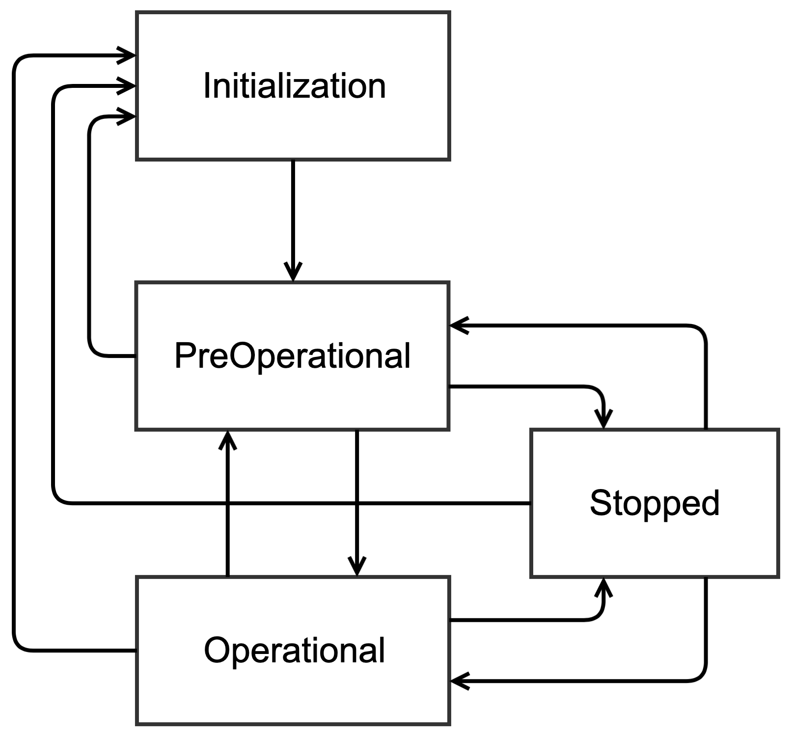
Table - NMT Slave States
Figure - NMT State Diagram of a CANopen Device in the Using Communication Objects page shows a typical NMT slave state diagram, and where the function CANopen_NmtStateSet() allows you to transition the state.
Figure - NMT State Diagram of a CANopen Device#
Node State Get#
The function CANopen_NmtStateGet() returns the current CANopen NMT state.
NMT Mode | Description |
|---|---|
CANOPEN_INIT | Node is in NMT state Initialization. |
CANOPEN_PREOP | Node is in NMT state Pre-operational. |
CANOPEN_OPERATIONAL | Node is in NMT state Operational. |
CANOPEN_STOP | Node is in NMT state Stopped. |
Table - NMT Slave States
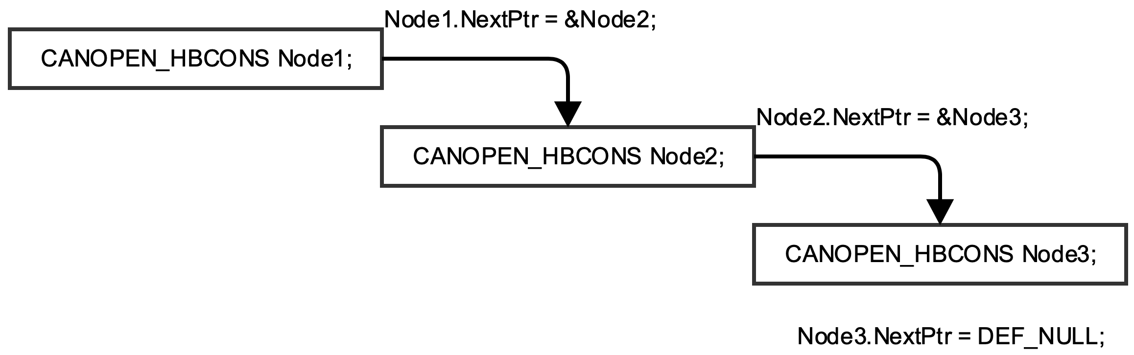
Heartbeat Consumer#
If a node enables the heartbeat consumer, this node will be able to monitor heartbeat producer messages sent by other nodes on the network. Multiple producer nodes can be linked together to form a list of monitored nodes. Listing - CANopen Heartbeat Structure in the Using Communication Objects page shows the heartbeat structure used to monitor a producer node.
Figure - Monitored Nodes List in the Using Communication Objects page shows how to link these structures together to monitor more than one node at the same time.
A few functions, described below, are available to get pieces of information about a given producer node.
Listing - CANopen Heartbeat Structure#
struct canopen_hbcons {
CANOPEN_HBCONS *NextPtr; /**< Link to next consumer in active chain */
CANOPEN_NODE_STATE State; /**< Received Node-State */
CPU_INT16S TmrId; /**< Timer Identifier */
CPU_INT16U TimeMs; /**< Time (Bit00-15 when read object) */
CPU_INT08U NodeId; /**< NodeId (Bit16-23 when read object) */
CPU_INT08U MissedEventCnt; /**< Event Counter */
};Figure - Monitored Nodes List#
Events Get#
The function CANopen_NmtHbConsEventsGet() returns the number of missed heartbeat for a given node. That is the number of times the producer heartbeat message has not been received by the consumer node within the heartbeat consumer time.
Last State Get#
The function CANopen_NmtHbConsLastStateGet() returns the last NMT state (Stopped, Pre-operational, Operational, Initialization) for a given node.