SD#
Integrating SD Into Your Project#
Micrium OS IO-SD is composed of several components, each of which is a set of files that implement specific functions. To use IO-SD, you must add these files to your project and populate your RTOS Description File .
Starting the IO SD Module Quickly#
Micrium offers a quick example application that demonstrates how to initialize, add a controller, and start the Micrium OS IO SD module. We highly recommend that you start with one of these examples.
Configuring IO-SD#
Micrium OS IO-SD module can be configured to optimize memory usage and features. See SD Core Run-Time Configurations for more information about configuring the SD core module at run-time.
SD Configuration#
This section describes the configurations related to Micrium OS IO-SD.
SD Core Run-Time Configurations#
This section describes Micrium OS IO-SD core run-time configurations.These configurations are optional and can usually be ignored until the very late stages of your application design.
Optional Pre-Init Configuration#
Pre-init configuration can be performed by calling dedicated configuration functions before IO_Init() is called. If no explicit pre-init configuration is performed, default values will be used. These default values are stored in SD_InitCfgDflt, which is defined in sd.c.
Memory Segment#
This module allocates control data and buffers used for data transfers with the cards. It has the ability to use different memory segments for the control data and the data buffers.
Type | Function to call | Default | Field from default configuration structure |
|---|---|---|---|
MEM_SEG* | SD_ConfigureMemSeg() | .MemSegPtr .MemSegBufPtr |
Maximum Number of SDIO Function Handles#
Configures the maximum number of SDIO functions can be used simultaneously.
Type | Function to call | Default | Field from default configuration structure |
|---|---|---|---|
CPU_SIZE_T | SD_ConfigureIO_FnctHandleQty() | Unlimited number of SDIO function handles | .IO_FnctQtyTot |
Maximum Number of SD Events#
Configures the maximum number of SD events that can be queued. Events include card connection and disconnection, SDIO card interruptions, and data transfer completions.
Type | Function to call | Default | Field from default configuration structure |
|---|---|---|---|
CPU_SIZE_T | SD_ConfigureEventQty() | Unlimited number of SD events | .EventQtyTot |
Maximum Number of SD Data Transfers#
Configures the maximum number of SD data transfers that can be submitted simultaneously.
Type | Function to call | Default | Field from default configuration structure |
|---|---|---|---|
CPU_SIZE_T | SD_ConfigureXferQty() | Unlimited number of SD data transfers | .XferQtyTot |
Event Functions#
Configures a set of application callbacks to be called on certain SD events (card insertion, card removal, etc.).
Type | Function to call | Default | Field from default configuration structure |
|---|---|---|---|
SD_EVENT_FNCTS | SD_ConfigureEventFncts() | None. | .EventFnctsPtr |
Core Task Stack#
The core task handles all the card-related events such as card insertion, removal, etc. This configuration allows you to set the stack pointer and the stack size (in quantity of elements).
Type | Function to call | Default | Field from default configuration structure |
|---|---|---|---|
CPU_INT32Uvoid * | SD_ConfigureCoreTaskStk() | A stack of 512 elements allocated on Common 's memory segment. | .CoreTaskStkPtr .CoreTaskStkSizeElements |
Async Task Stack#
The async task handles all the data transfers. This configuration allows you to set the stack pointer and the stack size (in quantity of elements).
Type | Function to call | Default | Field from default configuration structure |
|---|---|---|---|
CPU_INT32Uvoid * | SD_ConfigureAsyncTaskStk() | A stack of 512 elements allocated on Common 's memory segment. | .AsyncTaskStkPtr .AsyncTaskStkSizeElements |
Optional Post-Init Configurations#
This section describes the configurations that can be set at any time during execution after you called the function IO_Init().
These configurations are optional. If you do not set them in your application, the default configurations will apply.
Standard Requests Timeout#
Timeout, in milliseconds, for the SD card operations before timing out.The SD controller implements a hardware timeout. This timeout has been implemented only as a safety feature, as it should never expire. You should not set this timeout to a value lower than 200 ms.
Type | Function to call | Default |
|---|---|---|
CPU_INT32U | SD_OperationsTimeoutSet() | Infinite |
Core Task Priority#
The IO-SD module will create a task that handles the SD card-related events. You can change the priority of the created task at any time.
Type | Function to call | Default |
|---|---|---|
RTOS_TASK_PRIO | SD_CoreTaskPrioSet() |
Async Task Priority#
The IO-SD module will create a task that handles the SD data transfers. You can change the priority of the created task at any time.
Type | Function to call | Default |
|---|---|---|
RTOS_TASK_PRIO | SD_AsyncTaskPrioSet() |
SD Programming Guide#
Initial Setup of SD Module#
This section describes the basic steps required to initialize the SD module and to add an SD controller.
Initializing the IO-SD Module#
The first step is to initialize the SD Bus module core. This is done by calling the function IO_Init().
Note that the function IO_Init() will initialize all the IO sub-modules you have in your project, so there is no need to call it for each sub-module. For instance, if you have an SPI master in your project as well, you must not call IO_Init() twice.
Listing - Example of Call to IO_Init() in the Initial Setup of SD Module page shows an example of a call to IO_Init().
Listing - Example of Call to IO_Init()#
RTOS_ERR err;
IO_Init(&err);
if (err.Code != RTOS_ERR_NONE) {
/* An error occurred. Error handling should be added here. */
}Adding Your SD Bus Controller(s)#
Once you have successfully initialized the IO-SD module, you can start adding your SD bus controller(s). This is done by calling the function SD_BusAdd(). This function must be called for each SD bus controller you want to add.
Listing - Example of Call to SD_BusAdd() in the Initial Setup of SD Module page shows an example of a call to SD_BusAdd() using default arguments. In this example, SD bus controller "sd0" is added to the IO-SD module. For more information on how to register an SD Bus controller (if you need to write your own BSP), see SD Bus Controller Registration to the Platform Manager .
Listing - Example of Call to SD_BusAdd()#
RTOS_ERR err;
SD_BUS_HANDLE sd_handle;
sd_handle = SD_BusAdd("sd0",
&err);
if (err.Code != RTOS_ERR_NONE) {
/* An error occurred. Error handling should be added here. */
}Starting Your SD Bus Controller(s)#
Once you have successfully added your SD Bus controller(s), you must start it/them. This is done by calling the function SD_BusStart(). This function must be called for each SD Bus controller you have added.
Listing - Example of Call to SD_BusStart() in the Initial Setup of SD Module page shows an example of call to SD_BusStart().
Listing - Example of Call to SD_BusStart()#
RTOS_ERR err;
SD_BusStart(sd_handle,
&err);
if (err.Code != RTOS_ERR_NONE) {
/* An error occurred. Error handling should be added here. */
}SD Hardware Porting Guide#
The Micrium OS SD Bus module uses a hardware driver that can be customized for any SD Bus controller using a Board Support Package (BSP). The BSP has two purposes:
It initializes and configures any resources needed by the SD Bus controller, but which are provided by an external module.
It provides hardware information to the SD Bus driver.
We provide example BSPs for some popular platforms. If one is available for your platform, we recommend that you use it as a starting point. However, if no example BSP is available for your platform, the information in this section will help you understand how to correctly port the SD Bus module to your platform.
Note that each SD Bus controller (that you are planning to use) will require a BSP, and all the steps described in this section must be performed for each of them.
SD BSP Functions Guide#
A Board Support Package contains a set of functions that support your specific hardware platform on Micrium OS. These functions are called by the SD Bus driver to perform hardware configuration, or initialization of IO pins, interrupts, and so on. It is your responsibility to either create these functions from scratch or to modify example code to fit your needs and the specifics of your hardware.
Each of these functions is described below.
Initialize#
The first function you should implement is a generic initialization function. This function is called by the driver only once at initialization. Listing - Init Function Signature in the SD BSP Functions Guide page shows the signature of this function.
Listing - Init Function Signature#
CPU_BOOLEAN BSP_SD_SDHC_Init (SD_CARD_CTRLR_ISR_HANDLE_FNCT isr_fnct,
SD_CARD_DRV *p_sd_card_drv);Its purpose is to initialize and allocate resources that will be necessary to the SD Bus controller.
The initialization function receives two arguments: isr_fnct and p_sd_card_drv, which are used when handling interrupts from the SD Bus controller. The argument isr_fnct is a pointer to a driver function that must be called when an SD Bus interrupt occurs, and this driver function takes p_sd_card_drv as an argument. So it is important to save these as global variables in your BSP.
You must return DEF_OK from this function if it executes successfully, or DEF_FAIL, otherwise.
Clock Enable#
The Clock Enable function is called by the driver when the SD Bus controller is started. Listing - Clock Enable Function Signature in the SD BSP Functions Guide page shows the signature of the function.
Listing - Clock Enable Function Signature#
CPU_BOOLEAN BSP_SD_SDHC_ClkEn (void);Its purpose is to enable the source clock of the SD Bus controller.
You must return DEF_OK from this function if it executes successfully, or DEF_FAIL, otherwise.
I/O Configuration#
The I/O Configuration function is called by the driver when the SD Bus controller is started. Implementing this function is not mandatory if the SD Bus controller I/O does not require configuration. Listing - IO Configure Function Signature in the SD BSP Functions Guide page shows the signature of the function.
Listing - IO Enable Function Signature#
CPU_BOOLEAN BSP_SD_SDHC_IO_Cfg (void);Its purpose is to configure the I/O pins for the SD Bus controller.
You must return DEF_OK from this function if it executes successfully, or DEF_FAIL, otherwise.
Interrupt Configuration#
The Interrupt Configuration function is called by the driver when the SD Bus controller is started. Listing - Interrupt Configure Function Signature in the SD BSP Functions Guide page shows the signature of the function.
Listing - Interrupt Configure Function Signature#
CPU_BOOLEAN BSP_SD_SDHC_IntCfg (void);Its purpose is to configure the interrupt(s) of the SD Bus controller.
You must return DEF_OK from this function if it executes successfully, or DEF_FAIL, otherwise.
Power Configuration#
The Power Configuration function is called by the driver when the SD Bus controller is started. Implementing this function is not mandatory if the SD Bus controller power supply does not require configuration. Listing - Power Configure Function Signature in the SD BSP Functions Guide page shows the signature of the function.
Listing - Power Configure Function Signature#
CPU_BOOLEAN BSP_SD_SDHC_PwrCfg (void);Its purpose is to configure the power of the SD Bus controller.
You must return DEF_OK from this function if it executes successfully, or DEF_FAIL, otherwise.
Start#
The Start function is called by the driver each time the SD Bus controller is started. It is always called after all the "configure" functions. Implementing this function is not mandatory if there is nothing further to do when the controller is started. Listing - Start Function Signature in the SD BSP Functions Guide page shows the signature of the function.
Listing - Start Function Signature#
CPU_BOOLEAN BSP_SD_SDHC_Start (void);Its main purpose is to perform any operation required when the SD Bus controller is started.
You must return DEF_OK from this function if it executes successfully, or DEF_FAIL, otherwise.
Stop#
The Stop function is called by the driver when the SD Bus controller is stopped. Implementing this function is not mandatory if there is nothing further to do when the controller is stopped. Listing - Stop Function Signature in the SD BSP Functions Guide page shows the signature of the function.
Listing - Stop Function Signature#
CPU_BOOLEAN BSP_SD_SDHC_Stop (void);Its purpose is to perform any operation required when the SD Bus controller is stopped.
You must return DEF_OK from this function if it executes successfully, or DEF_FAIL, otherwise.
Clock Frequency Get#
The Clock Frequency Get function is called by the driver when the SD bus clock is configured. It is used to determine the clock divider that must be used to achieve the desired SD bus clock. The function must always return the clock frequency, in hertz, of the clock that feeds the SD Bus controller.
Listing - Clock Frequency Get Function Signature in the SD BSP Functions Guide page shows the signature of the function.
Listing - Clock Frequency Get Function Signature#
CPU_INT32U BSP_SD_SDHC_ClkFreqGet (void);Signal Volt Set#
The Signal Volt Set function is used to set the level of voltage for the signaling lines. The SD_CARD_SIGNAL_VOLT enum contains the voltage level to be set.
SD_CARD_SIGNAL_VOLT can take this value:
SD_CARD_SIGNAL_VOLT_1_8
SD_CARD_SIGNAL_VOLT_3_3
SD_CARD_SIGNAL_VOLT_AUTO
Listing - Signal Volt Set Function Signature in the SD BSP Functions Guide page shows the signature of the function.
Listing - Signal Volt Set Function Signature#
CPU_BOOLEAN BSP_SD_SDHC_SignalVoltSet (SD_CARD_SIGNAL_VOLT volt);You must return DEF_OK from this function if it executes successfully, or DEF_FAIL, otherwise.
Capabilities Get#
The Capabilities Get function is called by the driver when the SD Bus is started. It is used to determine the capabilities of the hardware. The driver will compute the capabilities based on the SD Host controller's reported capabilities. However, if for some reason, some capabilities are not available on your board, this function allows you to override the capabilities reported by the SD host controller. The function must always return the host capabilities as a bitmap of capabilities. This bitmap contains the host controller voltage operation and it bus width.
SD_HOST_CAPABILITIES can take this value :
Bus Voltage
SD_CAP_BUS_VOLT_3_3
SD_CAP_BUS_VOLT_3
SD_CAP_BUS_VOLT_1_8
Bus Signal Voltage
SD_CAP_BUS_SIGNAL_VOLT_3_3
SD_CAP_BUS_SIGNAL_VOLT_1_8
Bus Width
SD_CAP_BUS_WIDTH_1_BIT
SD_CAP_BUS_WIDTH_4_BIT
SD_CAP_BUS_WIDTH_8_BIT
Listing - Capabilities Get Function Signature in the SD BSP Functions Guide page shows the signature of the function.
Listing - Capabilities Get Function Signature#
void BSP_SD_SDHC_CapabilitiesGet (SD_HOST_CAPABILITIES *p_capabilities);ISR Handling#
Each SD Bus controller driver has an ISR handler function that must be called each time an SD Bus interrupt is triggered. However, for most platforms, it will be necessary to implement an intermediate ISR handler in the BSP. This BSP ISR will then call the driver's ISR handler. This is necessary, as some interrupt controllers may require the interrupt status to be cleared each time it is triggered. It is also necessary if your interrupt controller does not support passing an argument to the interrupt vector, as the driver's ISR handler takes the p_sd_card_drv received in the Init() function of the BSP as an argument.
Listing - Example of BSP ISR Implementation in the SD BSP Functions Guide page shows an example of an ISR handler implemented in the BSP if using the CMSIS standard.
Listing - Example of BSP ISR Implementation#
void SDIO_IRQHandler (void)
{
OSIntEnter();
BSP_SD_SDHC_ISR_Fnct(BSP_SD_SDHC_DrvPtr);
OSIntExit();
}SD Hardware Information#
Hardware Driver Information#
The SD Bus driver requires information about the SD Bus controller on your MCU, which you can provide using a structure of type SD_CARD_CTRLR_DRV_INFO. This information can be found in the manual for your MCU.
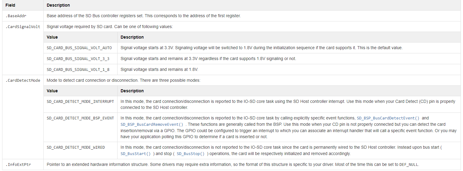
Table - SD_CARD_CTRLR_HW_INFO Structure in the SD Hardware Information page describes each configuration field available in this structure.
Table - SD_CARD_CTRLR_HW_INFO Structure#
BSP API Structure#
In order to provide a pointer to the BSP functions for the SD Bus controller driver, you must create a structure of type SD_CARD_CTRLR_BSP_API.
Table - SD_CARD_CTRLR_BSP_API Structure in the SD Hardware Information page describes each field available in this structure.
Table - SD_CARD_CTRLR_BSP_API Structure#
Field | Description |
|---|---|
.Init | Pointer to the BSP initialization function. |
.ClkEn | Pointer to the BSP clock enable function. |
.IO_Cfg | Pointer to the BSP I/O configure function. |
.IntCfg | Pointer to the BSP interrupt configure function. |
.PwrCfg | Pointer to the BSP power configure function. |
.Start | Pointer to the BSP start function. |
.Stop | Pointer to the BSP stop function. |
.ClkFreqGet | Pointer to the BSP clock frequency get function. |
.SignalVoltSet | Pointer to the BSP signal voltage set function. |
.CapabilitiesGet | Pointer to the BSP capabilities get function. |
.BSP_API_ExtPtr | Pointer to extended BSP API functions that could be required by your driver. Most of the time this can be set to DEF_NULL. |
Listing - Example of BSP API Structure in the SD Hardware Information page shows an example of a BSP API structure.
Listing - Example of BSP API Structure#
const SD_CARD_CTRLR_BSP_API BSP_SD_SDHC_BSP_API = {
.Init = BSP_SD_SDHC_Init,
.ClkEn = BSP_SD_SDHC_ClkEn,
.IO_Cfg = BSP_SD_SDHC_IO_Cfg,
.IntCfg = BSP_SD_SDHC_IntCfg,
.PwrCfg = BSP_SD_SDHC_PwrCfg,
.Start = BSP_SD_SDHC_Start,
.Stop = BSP_SD_SDHC_Stop,
.ClkFreqGet = BSP_SD_SDHC_ClkFreqGet,
.SignalVoltSet = BSP_SD_SDHC_SignalVoltSet,
.CapabilitiesGet = BSP_SD_SDHC_CapabilitiesGet,
.BSP_API_ExtPtr = DEF_NULL
};Device Hardware Information#
The last step is to create the main device hardware information structure.
Table - SD_CARD_CTRLR_DRV_INFO Structure in the SD Hardware Information page describes each configuration field available in this structure.
Table - SD_CARD_CTRLR_DRV_INFO Structure#
Field | Description |
|---|---|
.HW_Info | Structure explained above in Hardware Driver Information . |
.DrvAPI_Ptr | Pointer to the driver API structure you are using with your driver. Some drivers may provide more than one API structure. |
.BSP_API_Ptr | Pointer to the BSP API structure as described above in BSP API Structure . |
SD Controller Registration to the Platform Manager#
Once the hardware information structure for your SD Bus controller is ready, it must be registered with the Platform Manager . This should typically be done using the BSP_OS_Init() function that is located in the file bsp_os.c.
There is a macro located in the file sd.h that you can call to register an SD Bus controller. The macro is named IO_SD_CARD_CTRLR_REG().
Listing - Example of SD Bus Controller Registration in the SD Controller Registration to the Platform Manager page shows an example of how to register an SD Bus controller.
Listing - Example of SD Bus Controller Registration#
#include <rtos_description.h>
#if defined(RTOS_MODULE_IO_SD_AVAIL)
#include <rtos/io/include/sd.h>
#include <rtos/io/include/sd_card.h>
#endif
#if defined(RTOS_MODULE_IO_SD_AVAIL) (1)
BSP_HW_INFO_EXT(const SD_CARD_CTRLR_DRV_INFO, BSP_SD_SDHC_BSP_DrvInfo);
#endif
void BSP_OS_Init (void)
{
/* ... */
/* ------------- REGISTER SD CONTROLLERS ------------- */
#if defined(RTOS_MODULE_IO_SD_AVAIL)
IO_SD_CARD_CTRLR_REG("sd0", &BSP_SD_SDHC_BSP_DrvInfo);
#endif
}(1) Since the hardware information global variables are declared in another file, you must declare them as external in your bsp_os.c file. Always use the BSP_HW_INFO_EXT() macro.