Theory of Operation#
This page describes the steps required to bring up a network with coexistence features enabled. The page is divided into multiple subsections detailing each step required:
Bringing Up a Standalone Zigbee Network introduces building and flashing the Z3Light and Z3Switch applications, and sending commands over the network between them.
Adding the Throughput Library to Zigbee Devices. The applications are rebuilt with the throughput library, flashed, and network traffic created between them.
Adding the Coexistence Feature to Zigbee Devices. Coexistence features are added and the coexistence backplane board is introduced. Network traffic is created using the throughput library added in the previous step.
Using PTA Controller in the Test Setup. The PTA Controller application is built and flashed to a device, which then is introduced to the test setup as a coexistence controller device.
Using Coexistence Features in Bluetooth Devices. Coexistence features are set up on a Bluetooth network, in a procedure that builds on the instructions for setting up a Zigbee network.
Configuring Devices in Multi-Radio Mode. The coexistence board and applications are configured for multi-radio mode.
Replacing PTA Controller with an External Wi-Fi Device. The PTA Controller device is replaced with an external Wi-Fi chipset.
Note: This section walks through the steps required to set up coexistence on EFR32MG12-based devices. Refer to Jumper Wire Configurations for Different Boards/Devices regarding connection and wiring information for other compatible devices.
Note: Zigbee EmberZNet SDK introduced a new component-based architecture, along with a Project Configurator and other tools to replace AppBuilder and plugin configuration. In general, the new software components are comparable to the plugins. When applicable, instructions for both version 7.0 and higher and 6.10.x and lower are provided. For more information, see AN1301: Transitioning from Zigbee EmberZNet SDK 6.x to SDK 7.x.
Bringing Up a Standalone Zigbee Network#
The first step in setting up for coexistence testing is understanding how to set up a Zigbee network between two devices. For this purpose, we recommend following the steps in the applicable quick-start guide for your version to build, flash, and verify network commands between the Z3Light and Z3Switch example applications. These applications will be modified and used in subsequent steps. This allows you to become familiar with application development using the Zigbee stack. It is also important to be familiar with the steps in the quick-start guide as the document will be referred to extensively in the following steps. Quick-start guides can be found through the list of documents on the Simplicity Studio Launcher perspective, and on the Silicon Labs website under Zigbee documentation. Direct links to the documents follow:
QSG106: Zigbee EmberZNet PRO Quick-Start Guide for SDK v6.10.x and Lower
QSG180: Zigbee EmberZNet Quick-Start Guide for SDK v7.0 and Higher
Adding the Throughput Library to Zigbee Devices#
This step explains how to modify the example applications to add the throughput library. The throughput library is an additional component/plugin available in the EmberZNet PRO stack that allows transmitting data between devices at controllable speeds. It is useful for the evaluation of network quality and connection stability. More information regarding the throughput library can be found in Throughput Library.
Rebuilding and Flashing the Images#
If you have not already done so in the previous section, follow the steps in the applicable quick-start guide to start the Z3Light and Z3Switch example applications. Otherwise return to the Simplicity IDE perspective for one of the examples. Customize the examples as described below, then follow the steps in the applicable quick-start guide to build and flash them to your devices.
In SDK 7.0 and higher#
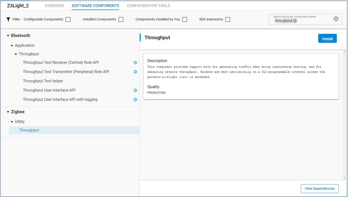
If the <project>.slcp file is not open, double-click it in the Project Explorer view to open it. Go to the Software Components tab and enter the keyword 'throughput' to search for the throughput component. Install the component. Repeat for the other example application.
In SDK 6.10.x and lower#
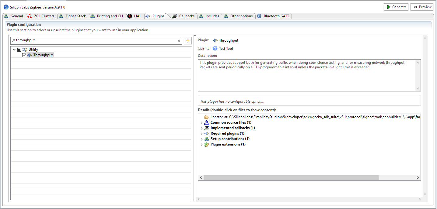
If the <project>.isc file is not open, double-click it in the Project Explorer view to open it. Do not generate the application yet. Go to the Plugins tab and enter the keyword “throughput” to search for the throughput library plugin. Check the checkbox next to the plugin name to enable the plugin. Repeat for the other example application.
Using the Throughput Library to Send Zigbee Traffic#
From Simplicity Studio, access the CLI consoles of the Z3Light and Z3Switch WSTKs. Refer to the applicable quick-start guide for instructions on opening CLI consoles.
In the console of the Z3Switch example, send the command info to display network information regarding the device. Note the Node ID in the command's response.
In the console of the Z3Light, send the following command
plugin throughput set-all <0xNodeID> 10 10 127 1 0 100000where NodeID is the node ID of the Z3Switch noted in step 2 above, typed as a hex number. This configures the throughput settings.
Still in the console of the Z3Light, send the following command:
plugin throughput start
A series of 10 packets is then sent from the Z3Light to the Z3Switch, generating Zigbee traffic. The Z3Switch console also indicates packets being received.
More information on the commands used in step 3 and 4 as well as other features of the throughput library can be found in section Throughput Library.
Adding the Coexistence Feature to Zigbee Devices#
This step describes the procedure to enable and configure coexistence features in the example applications. This section uses the Z3Light application as the example, however the same procedure can be used to enable coexistence on any application. The coexistence features are contained in an additional component/plugin available in the EmberZNet PRO stack. More information regarding the coexistence component/plugin can be found in Zigbee and OpenThread Coexistence with Wi-Fi.
Enabling the FEM driver component/plugin is also recommended. This provides visibility into the state of the radio for debugging purposes and monitoring radio activity.
Note: This procedure assumes you have created, built, flashed, and verified example applications with the Throughput library as described in section Adding the Throughput Library to Zigbee Devices.
Rebuilding and Flashing the Images#
Customize the examples as described below, then follow the steps in the applicable quick-start guide to build and flash them to your devices.
In SDK 7.0 and higher#
Open the Simplicity IDE perspective to access the project files.
In the Project Explorer view, open the <project_name>.slcp file. If you have just created the project, the file may already be open.
Click the Software Components tab, and type 'coexistence' in the search field. Select the RAIL Utility, Coexistence component.
Click Install to add the component to the project. A Configure control is now available.
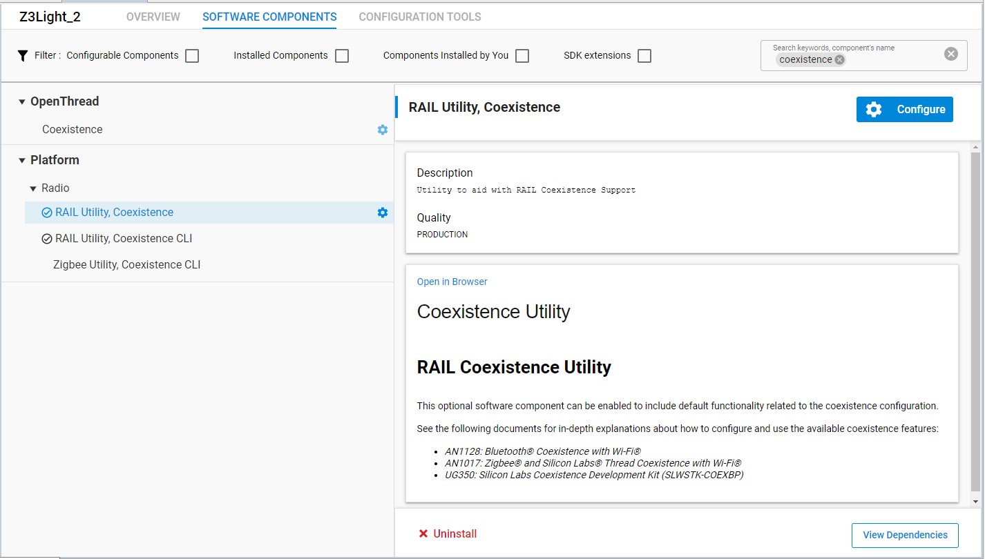
Click Configure to open the Component Editor.
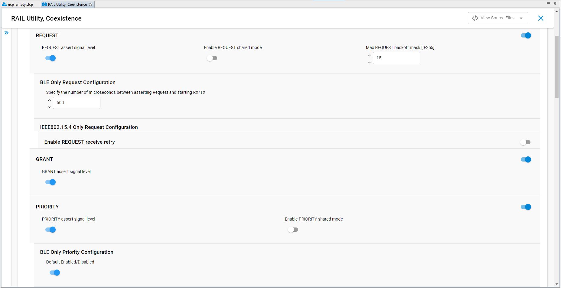
By default, most coexistence options on the Coexistence Configuration card are disabled. Disable anything that is enabled, and then enable the following:
Request Signal, with all options enabled except Shared mode.
Grant Signal
Priority Signal, with all options enabled except Shared mode.
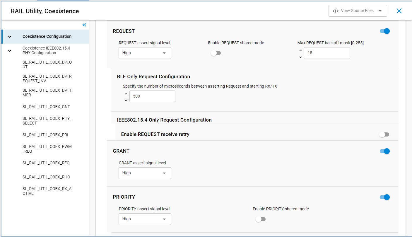
Changes are automatically saved, as shown at the top of the Component Editor.
A series of cards for different coexistence features are provided after the configuration card. Configure GPIO routes on the following cards:
SL_RAIL_UTIL_COEX_GNT (GRANT) = PC9
SL_RAIL_UTIL_COEX_PRI (PRIORITY) = PD12
SL_RAIL_UTIL_COEX_REQ (REQUEST) = PC10
SL_RAIL_UTIL_COEX_RHO (Radio Hold-off) = None
Close the Component Editor.
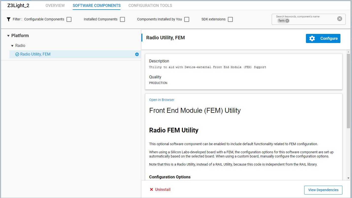
Enabling the FEM driver component is also recommended, to provide visibility into the state of the radio. On the Software Components tab, search for 'FEM'. Select the Radio Utility, FEM component.
Click Install, then click Configure to open the Component Editor.
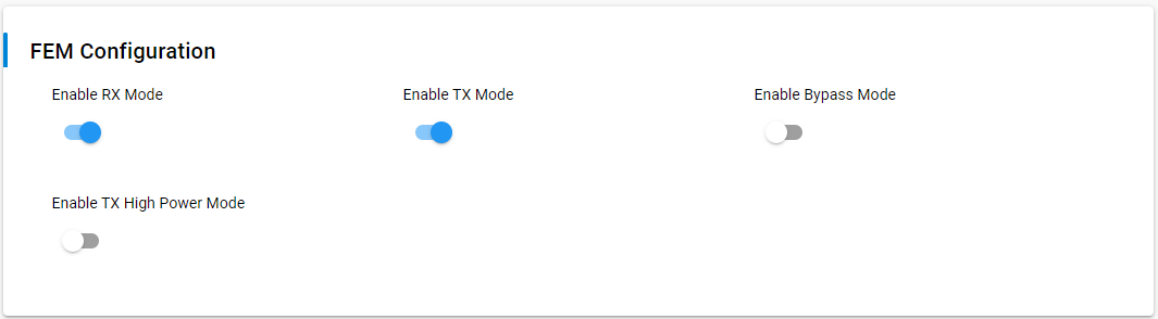
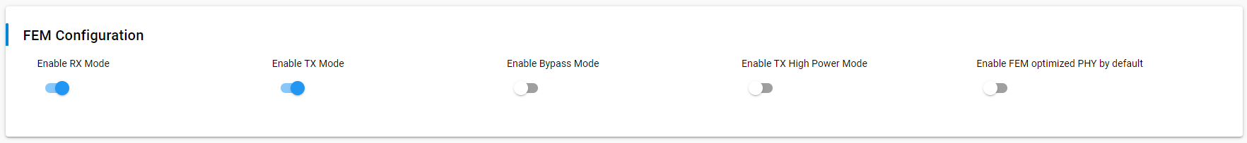
Configure the component as follows:
In the FEM Configuration card, enable RX Mode and TX Mode.
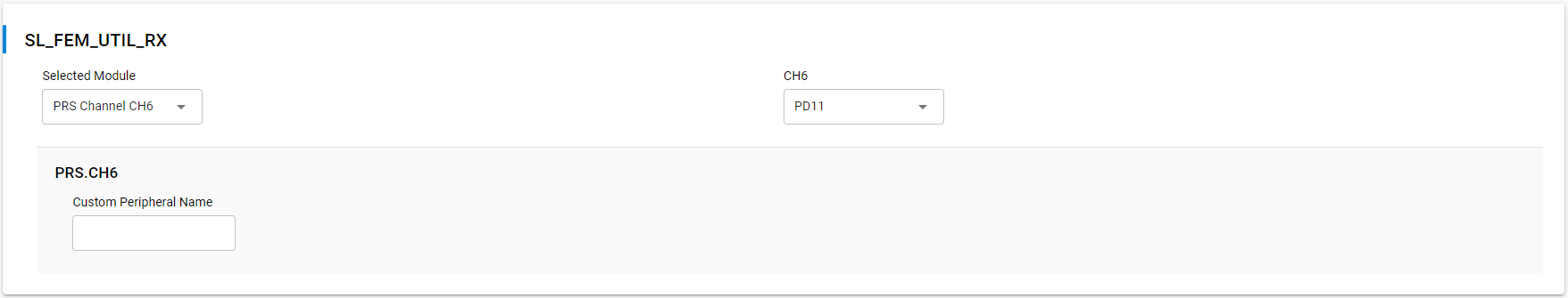
In the SL_FEM_UTIL_RX card, set Selected Module to PRS Channel CH6 and pin PD11.
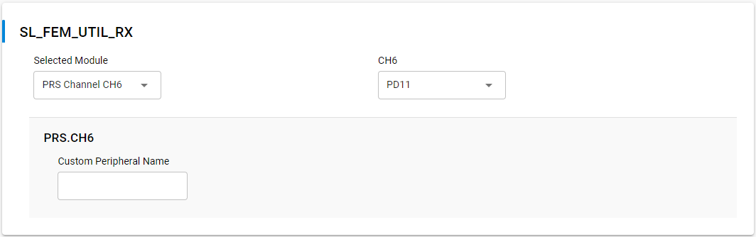
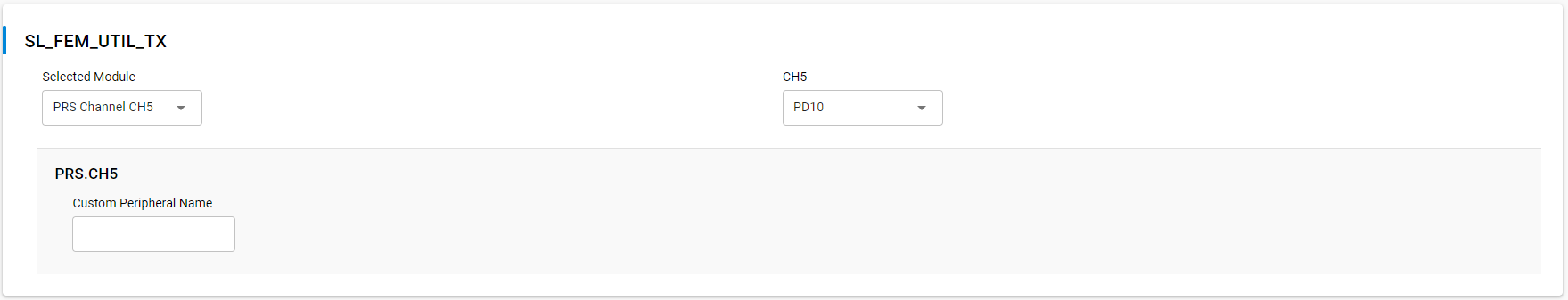
In the SL_FEM_UTIL_TX card, set Selected Module to PRS Channel CH5 and pin PD10.

In SDK 6.10.x and Lower#
Return to the Simplicity IDE perspective for the Z3Light sample application .isc file.
Go to the Plugins tab and search for the keyword 'coexistence' to find the coexistence configuration plugin.
Check the checkbox next to the plugin name to enable the plugin.
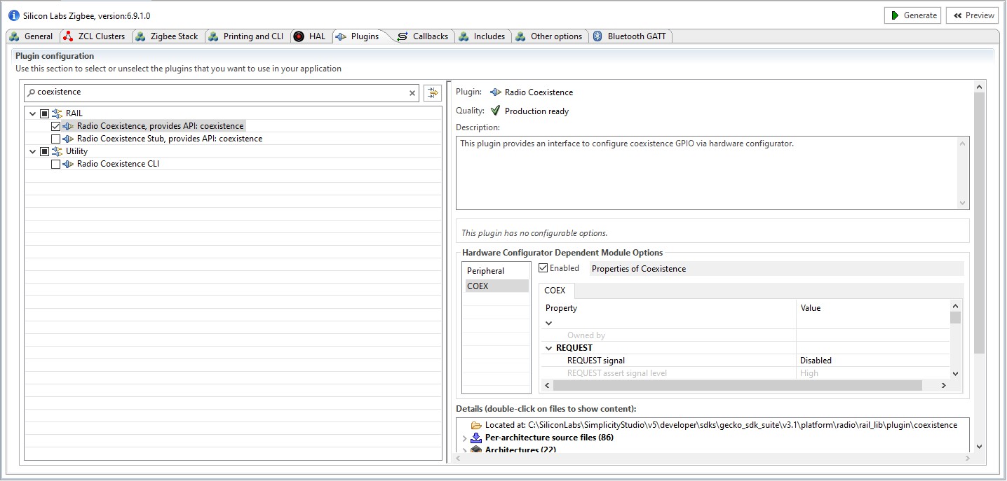
Uncheck the checkbox next to the Stub plugin to disable Stub functions.
In the menu on the right, make sure the Enabled box next to Properties of Coexistence is checked.
Modify the fields in the menu on the right as follows:
REQUEST Signal: PC10
GRANT Signal: PC9
PRIORITY Signal: PD12
RHO Signal: Disabled
Leave all other settings with their default values.
Still in the Plugins tab, search for keyword “fem” to bring the FEM driver plugin.
Check the checkbox next to the plugin name to enable the plugin.
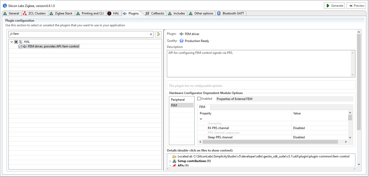
In the menu on the right, make sure the Enabled box next to Properties of External FEM is checked.
Modify the fields in the menu on the right as follows:
RX PRS channel: CH6
PRS channel 6 output pin: PD11
TX PRS channel: CH5
PRS channel 5 output pin: PD10
Enable RX mode: True
Enable TX mode: True
Leave all other settings with their default values.
Setting up the Coexistence Backplane Board#
Add the appropriate jumper wires and jumpers as shown in the following figure. This sets the GRANT line to always asserted, and allows the Z3Light to exercise the coexistence signals.
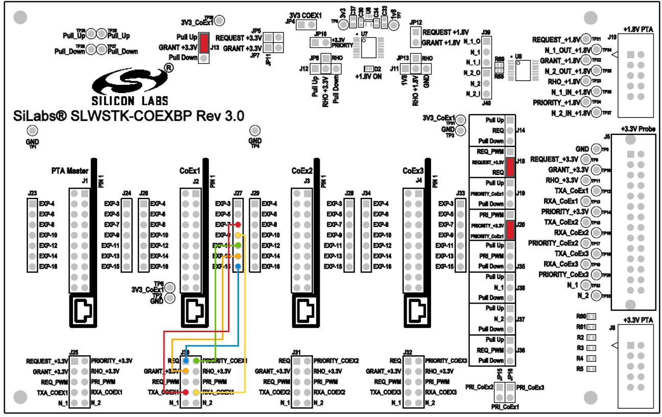
Plug the Z3Light board into the CoEx1 position (J2) in the Coexistence Backplane board. Follow the silk label for proper orientation.
If using a logic analyzer, probe the test points or pins in header J5 (+3.3V probe header) on the right side to access the following signals:
REQUEST_+3.3V – TP9 or J5 pin 2
GRANT_+3.3V – TP10 or J5 pin 4
PRIORITY_+3.3V – TP14 or J5 pin 12
TXA_CoEx1 – TP12 or J5 pin 8
RXA_CoEx1 – TP13 or J5 pin 10
Using the Throughput Library to Send Zigbee Traffic#
From Simplicity Studio, access the CLI consoles of the Z3Light and Z3Switch WSTKs.
In the console of the Z3Switch example, send the command info to display network information regarding the device. Note the Node ID in the command's response.
In the console of the Z3Light, send the following command
plugin throughput set-all <0xNodeID> 10 10 127 1 0 100000where NodeID is the node ID of the Z3Switch noted in step 2 above, typed as a hex number. This configures the throughput settings.
Still in the console of the Z3Light, send the following command:
plugin throughput startA series of 10 packets is then sent from the Z3Light to the Z3Switch, generating Zigbee traffic. The Z3Switch console also indicates packets being received.
More information on the commands used in step 3 and 4 as well as other features of the throughput library can be found in section Throughput Library.
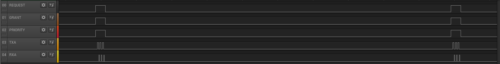
Activity corresponding to sending 10 packets can also be observed on the logic analyzer. It will look similar to the following capture.
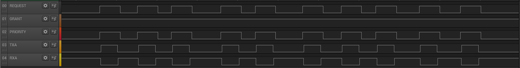
REQUEST and PRIORITY signals are asserted 10 times during the throughput run, indicating 10 attempts to send the messages. In addition, TXA is also asserted within these REQUEST cycles, indicating the radio was transmitting. GRANT signal is always asserted due to the configuration of the board. The RXA signal is de-asserted when the radio is transmitting, otherwise it remains asserted, indicating the radio is in receive mode.
Using PTA Controller in the Test Setup#
The PTA Controller application is a custom application. It is designed to assist in evaluating the coexistence features available in the stack by acting as a Wi-Fi controller device emulator. The PTA Controller only emulates the GPIO behaviors and cannot generate actual Wi-Fi traffic. More information regarding the features of the PTA Controller can be found in section PTA-Controller Application.
Note: This procedure uses the Z3Light and Z3Switch devices created and installed with the Coexistence Backplane board in the previous procedure.
Obtaining the PTA Controller Application#
The PTA Controller application is available for download on GitHub. Use the following link to obtain the binary files:
Follow the steps in the applicable quick-start guide to flash the PTA Controller application onto one of the boards.
Setting up the PTA Controller Device with the Coexistence Backplane Board#
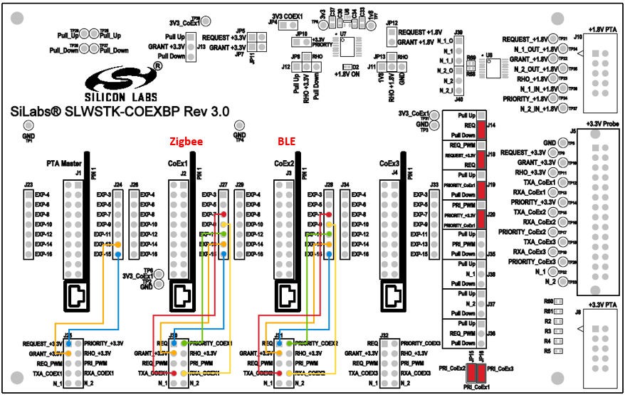
Remove the jumper from J13 (added to assert GRANT line in Setting Up the Coexistence Backplane Board) and add additional jumper wires required to communicate with the PTA Controller, as shown in the following diagram:
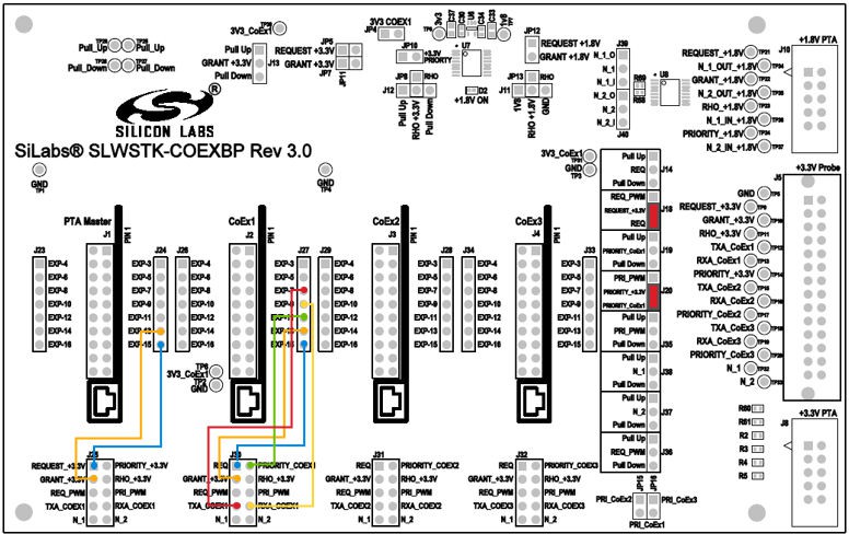
Plug PTA Controller device into dedicated header J1, on the left side of the board. Make sure the board is oriented according to the silk near the header.
Configuring the PTA Controller Application to Work with Z3Light#
The PTA Controller application features run-time configurable options to configure the behavior. By default, all additional features are turned off, and all signals are assumed active High.
Therefore, the PTA Controller will work with the Z3Light device as is, without needing additional configurations. Details regarding additional configurations can be found in PTA Controller Application.
Using the Throughput Library to Send Zigbee Traffic#
From Simplicity Studio, access the CLI consoles of the Z3Light and Z3Switch WSTKs.
In the console of the Z3Switch example, send the command info to display network information regarding the device. Note the Node ID in the command's response.
In the console of the Z3Light, send the following command:
plugin throughput set-all <0xNodeID> 10 10 127 1 0 100000where NodeID is the node ID of the Z3Switch noted in step 2 above, typed as a hex number. This configures the throughput settings.
Still in the console of the Z3Light, send the following command:
plugin throughput startA series of 10 packets is then sent from the Z3Light to the Z3Switch, generating Zigbee traffic. The Z3Switch console also indicates packets being received.
More information on the commands used in step 3 and 4 as well as other features of the throughput library can be found in section Throughput Library.
Activity corresponding to sending 10 packets can also be observed on the logic analyzer. It will look similar to the following capture.

REQUEST and PRIORITY signals are asserted 10 times during the throughput run, indicating 10 attempts to send the messages. Note here that the GRANT signal controlled by PTA Controller is also asserted and de-asserted with REQUEST. In default settings, the PTA Controller is configured to always GRANT when the peripheral device REQUESTs. In addition, TXA is also asserted within these REQUEST cycles, indicating the radio was transmitting. The RXA signal is de-asserted when the radio is transmitting, otherwise it remains asserted, indicating the radio is in receive mode.
Using Coexistence Features in Bluetooth Devices#
Coexistence features are also available in the Bluetooth SDK, and can be evaluated using the same hardware setup explained previously for Zigbee. For the following instructions, the coexistence backplane board must be configured as explained in section Configuring the PTA Controller Application to Work with Z3Light, with the PTA Controller device and coexistence device plugged in and connected to the Coexistence backplane board.
Setting up a Bluetooth Sample Application#
The Silicon Labs Bluetooth SDK contains many useful examples to test and run Bluetooth. For the purposes of demonstrating coexistence features in Bluetooth, the "NCP Empty” example will be used. Refer to the Bluetooth SDK Getting Started Guide for instructions on how to create a sample ncp-empty application and use it to advertise. For the purpose of generating Bluetooth PTA traffic in this test, only one Bluetooth device will be required.
Adding Coexistence Features to a Bluetooth Sample Application#
Once a sample Bluetooth application is set up, coexistence features can be added to the application using the following steps:
Open the Simplicity IDE perspective to access the project files.
In the Project Explorer view, open the <project_name>.slcp file (for example, ncp_empty.slcp). If you have just created the project, the file may already be open.
Click the Software Components tab, and type 'coexistence' in the search field. Select the RAIL Utility, Coexistence component.
Click Install to add the component to the project. A Configure control is now available.
Click Configure to open the Component Editor.
By default, most coexistence options on the Coexistence Configuration card are disabled. Disable anything that is enabled, and then enable the following:
Request Signal, with all options enabled except Shared mode.
Grant Signal
Priority Signal, with all options enabled except Shared mode.
Changes are automatically saved, as shown at the top of the Component Editor.
A series of cards for different coexistence features are provided after the configuration card. Configure GPIO routes on the following cards:
SL_RAIL_UTIL_COEX_GNT (GRANT) = PC9
SL_RAIL_UTIL_COEX_PRI (PRIORITY) = PD12
SL_RAIL_UTIL_COEX_REQ (REQUEST) = PC10
Close the Component Editor.
Enabling the FEM driver component is also recommended, to provide visibility into the state of the radio. On the Software Components tab, search for 'FEM'. Select the Radio Utility, FEM component.
Click Install, then click Configure to open the Component Editor.
Configure the component as follows:
In the FEM Configuration card, enable RX Mode and TX Mode.
In the SL_FEM_UTIL_RX card, set Selected Module to PRS Channel CH6 and pin PD11.
In the SL_FEM_UTIL_TX card, set Selected Module to PRS Channel 5 and pin PD10.
Rebuild and flash the new image to the coexistence device, and enable advertising as described in the Bluetooth SDK Getting Started Guide.
The following logic capture shows an example of the capture during Bluetooth advertising events:
Configuring Devices in Multi-Radio Mode#
Depending on the system requirements, multiple coexistence-enabled devices may need to coordinate network activity with Wi-Fi device using PTA. This can be achieved in coexistence features by enabling Shared mode. Shared mode allows multiple devices to operate on a single coexistence line by configuring the GPIO to open-drain or open-source, with external pull resistors. The coexistence backplane board already contains pull resistors that can be enabled through jumpers. Note that, for this section, an additional WSTK board with BRD4161 or BRD4162 radio board is required.
The following steps explain how to set up the coexistence board and sample applications for multi-radio configuration:
In a Zigbee sample application, after setting up all coexistence options as explained in section Rebuilding and Flashing the Images, also enable Shared mode under Request and Priority options.
Rebuild and flash the new image to a WSTK device with BRD4161 radio board.
In a Bluetooth sample application, after setting up all coexistence options as explained in section Adding Coexistence Features to a Bluetooth Sample Application, also enable Shared mode under Request and Priority options.
Rebuild and flash the new image to a different WSTK device with BRD4161 radio board.
Configure the Coexistence backplane board as shown in the following figure. Note that there are three WSTK boards now plugged into the Coexistence backplane board.
Enable advertising on the Bluetooth coexistence device, and generate throughput activity on the Zigbee coexistence device.
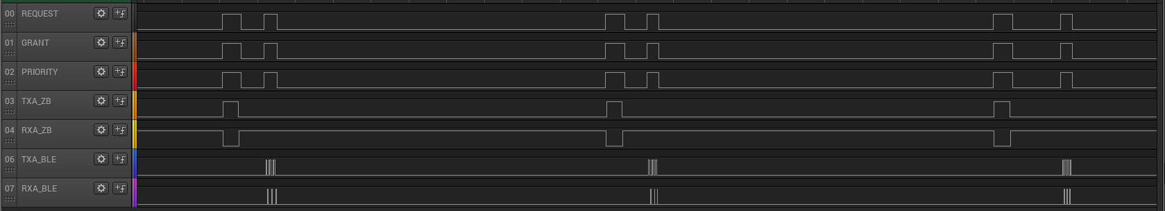
The following image shows an example of the logic capture when both Zigbee and Bluetooth are communicating on the same coexistence lines. Note that only one or the other radio is using the coexistence lines at a time. This is developed into the Shared mode options, as a radio must check the coexistence lines to make sure they are available, before attempting to use them.
Replacing PTA Controller with an External Wi-Fi Device#
Once evaluation has been completed using the PTA Controller application, the next step is to use an actual external Wi-Fi chipset to interface with the coexistence features in the Z3Light device. The following steps detail how this can be achieved.
Remove the PTA Controller device.
Connect the external Wi-Fi device coexistence signals to the appropriate header.
If using a +3.3V signals Wi-Fi device, use header J8.
If using a +1.8V signals Wi-Fi device, use header J10.
Refer to section Coexistence Backplane Board for more detail.
The PTA signals are routed from the CoEx component/plugin headers to the probe headers J8 and J10 when configured to be used, so the Wi-Fi device should be able to receive and respond to the signal states.